
94% of researchers rate our articles as excellent or good
Learn more about the work of our research integrity team to safeguard the quality of each article we publish.
Find out more
ORIGINAL RESEARCH article
Front. Phys., 01 February 2024
Sec. Complex Physical Systems
Volume 12 - 2024 | https://doi.org/10.3389/fphy.2024.1332187
This article is part of the Research TopicStatic and Dynamic Pattern Formation from Nano to Macro scalesView all 9 articles
The injection of a fluid into another fluid causes a spatiotemporal pattern along the injection front. Viscous fingering is a well-known example when the replaced material is a viscous fluid. Notably, most fluids are, in reality, viscoelastic, i.e., they behave as an elastic solid over short timescales. For this reason, it is important to study the situation when the replaced fluid is viscoelastic. In this study, we observed a dynamics of fluids when an incompressible organic liquid was injected into an oleophilic Hele–Shaw cell filled with an aqueous viscoelastic fluid made of a wormlike micellar solution. We found extensive tip splitting of the injection front, which led to thin fingers with a characteristic size comparable to four times the cell thickness. We examined the material properties and suggest that the thin fingering pattern observed in our system is due to the delamination of viscoelastic fluid from the bottom substrate surface. Our result shows that the effect of interfacial energy in the existing solid layer should be considered in the injection process.
When a fluid is injected into a confined space filled with another fluid, existing fluids are displaced and often create complex pattern dynamics. Here, the injection of fluid introduces the non-equilibrium condition through kinetic energy, momentum, and chemical components, leading to the appearance of a dissipative structure created under far from equilibrium conditions [1]. The injection of fluid into a thin cell, known as a Hele–Shaw cell, filled with another viscous fluid exhibits viscous fingering [2, 3]. Recent studies on viscous fingering have adopted the use of chemical reactions [4, 5, 6, 7], or miscibility of the fluid [8, 9].
Viscous liquids are useful yet only provide an approximation. Actual fluids can have elastic aspects, which we call viscoelasticity. Understanding the impact of viscoelasticity on macroscopic dynamics is not only theoretically interesting but also important for industries like cosmetics and food manufacturing. The same goes for geophysical studies. Recent research on earthquakes, as well as slow earthquakes [10], has revealed that the migration of water (a viscous liquid) in a subducting mantle (a viscoelastic material) can trigger earthquakes [11, 12, 13]. Therefore, it is crucial to study the effect of viscoelasticity to get a better understanding of these phenomena.
For the above situation, it is relevant to investigate systems in which a viscous fluid is injected into a viscoelastic fluid. In this context, the injection of a fluid into an agarose gel has been studied [14]. Similarly, recent studies on viscoelastic fluids have also been conducted [15, 16, 17]. In their study, the main focus was given to the transition from viscous to elastic behavior. For this reason, the injected fluid in these studies often had similar wetting properties to the displaced fluid. In this study, we focus on the elastic outer fluid with special attention on the wetting of the substrate surfaces. Thus, we inject an organic liquid into a cell made of oleophilic substrates filled with aqueous viscoelastic fluid of a wormlike micellar solution. This solution is composed of a mixture of cetyltrimethylammonium bromide (CTAB) and sodium salicylate (NaSal) and is highly viscous [18, 19] and also elastic [20, 21, 22, 23, 24], even with only a few percent of additional chemicals to water.
In this paper, we describe the results from an experiment under the geometry of Hele–Shaw cells. An incompressible organic liquid is injected into a Hele–Shaw cell filled with a wormlike micellar solution. The injection speed is varied as a parameter but kept high enough to have the wormlike micellar solution elastic, and the spatiotemporal dynamics of the injection patterns are observed. The fingering pattern showed thick and thin fingers, and thin fingers are characterized by extensive tip-splitting. Based on the observed dynamics, the rheological relaxation time, and the wetting behavior, we suggest that thin fingering may represent the delamination of the viscoelastic fluid from the substrate. Interestingly, the wetting of elastic fluid on a substrate surface, which is typically the character of a liquid, plays an essential role in the fingering process.
The experimental system was a thin horizontal cell (Hele–Shaw cell) with a gap width of h = 0.5 mm. The cell was made using a polystyrene Petri dish (166,058, Thermo Fisher Scientific) as the lower plate and an acrylic plate (Mitsubishi Rayon Co., Ltd.) as the upper plate (Figure 1A). A Luer fitting (ISIS Co., Ltd.) was fixed at the center of the upper plate and used as an inlet for injecting inner fluids.
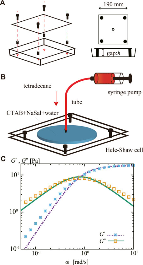
FIGURE 1. (A) Schematic representation of a Hele–Shaw cell made from a square Petri dish. The gap width between the two parallel plates was h = 0.5 mm. (B) Schematics of the experimental system. A Hele–Shaw cell was filled with the viscoelastic outer fluid, an aqueous mixture of CTAB and NaSal, and stored for 3 h. The inner fluid, tetradecane stained with oil red, was then injected steadily from the center of the cell. (C) Storage modulus G′ and loss modulus G″ of the viscoelastic outer fluid. The lines represent a fit by a Maxwell model with a single relaxation time, which gives us the shear modulus G =17.85±0.17 Pa and the relaxation time τ =1.23±0.03 s.
We purchased cetyltrimethylammonium bromide (CTAB) from Tokyo Chemical Industry Co., Ltd. And sodium salicylate (NaSal), tetradecane, and oil red from Wako Pure Chemical Industries Ltd. Fluorocarbon surface modifier was obtained from Fluoro technology (Fluorosurf; FS-1090J-2.0). We purified CTAB with the recrystallization method three times using a mixture of acetone and methanol. The inner fluid consisted of tetradecane colored with 0.2 wt% oil red. The outer fluid consisted of 1.82 wt% CTAB and 0.80 wt% NaSal, dissolved in pure water purified using the Millipore Milli-Q system. The CTAB and NaSal were mixed into the water while the temperature was 60°C.
The Hele–Shaw cell was filled with approximately 10 mL of the outer fluid and stored for 3 h before the experiment. Then, the inner fluid was injected from the center of the upper plate (Figure 1B). A syringe pump (CXF1010; ISIS Co., Ltd.) was used to inject the inner fluid at a nominally constant injection rate Q. We used a glass syringe (Tsubasa Industry Co., Ltd.) and a nylon tube (Nihon Pisco Co., Ltd.; diameter 2.5 mm) to ensure the high rigidity of the injection environment. Q was varied from 1.0 to 9.0 mL/min. The pattern dynamics were recorded from the bottom of the cell using a digital video camera (DMK37BUX273, The Imaging Source) at 16 bit and 30 Hz and analyzed using the ImageJ software [25].
The outer fluid is known to form a wormlike micellar solution and behave as a Maxwellian viscoelastic fluid with a single relaxation time [20, 21, 22, 26, 27]. The rheology of the outer fluid was measured from its oscillatory shear using a rheometer (MCR-302, Anton Paar) with cone plate (CP25-2, Anton Paar). We conducted linear oscillatory measurement with the amplitude of 10% shear at 20°C. The storage modulus G′ and loss modulus G″ are shown in Figure 1C. We estimated the shear modulus G and the relaxation time τ by fitting these observed data to equation G′(ω) = (Gω2τ2)/(1 + ω2τ2) and G′′(ω) = (Gωτ)/(1 + ω2τ2) [28] using the least squares with the Marquardt-Levenberg-algorithm adopted in gnuplot (the fitted lines are shown in Figure 1C); as a result, we obtained G = 17.85 ± 0.17 Pa and τ = 1.23 ± 0.03 s. We should remark that the flow speed V needs to be lower than the critical one Vc = h/τ = 0.4 mm/s to have the outer fluid viscous. In our experiment, the injection front extends at least one order of magnitude faster than Vc, as later shown in Figure 5. Thus, the outer fluid behaves elastically.
We here list the relevant physical properties of the samples; viscosity, density, surface tension, and contact angle. The viscosity of inner and outer fluid was 2.08 and 3.03 × 10³ mPa⋅s. The density of inner and outer fluids was 0.76 and 1.00 g/cm3. We measured the surface tension of inner and outer fluids with the Wilhelmy method (CBVP-A3, Kyowa) to have 26.6 and 31.1 mN/m. We found that the contact angle of the sample under air was almost the same for the top and bottom plates. The contact angle of outer fluids was 30°, while the contact angle of inner fluids was not detectable due to the spreading of droplets, indicating both plates are wettable to the inner fluid. However, we also observed that the bottom plate was found to be more wettable from the size of the spread droplet. When the fluorine coating was applied, the contact angles of the inner and outer fluids were approximately 73° and 80°. These measurements were conducted at 22°C ± 2°C.
In Figure 2, we present snapshots of typical fingering patterns observed with Q = 1.0, 3.0, 6.0, and 9.0 mL/min. The thick fingers appeared up to 2–3 s, independent of the injection rate Q. Then, eventually, the front showed significant splitting, resulting in numerous thin fingers with approximately 1.2–2.2 mm width, as exemplified in the snapshot Figure 2E. The thin fingers tended to meander and extend not only in radial but also in angular direction from the inlet.
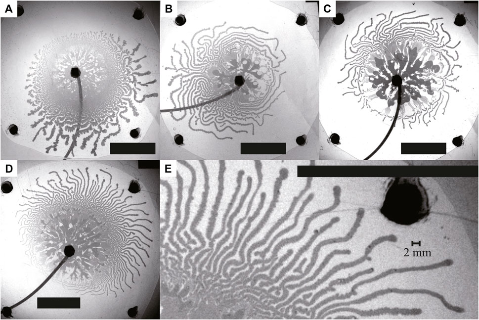
FIGURE 2. Snapshots of typical fingering patterns, where Q = (A) 1.0, (B) 3.0, (C) 6.0, and (D, E) 9.0 mL/min. Scale bar: 50 mm. The image in (E) is an enlarged image of (D). The snapshots were taken just before the inner fluid reached the edge of the outer fluid, which was (A) 60.00 s, (B) 20.00 s, (C) 10.00 s, and (D, E) 6.67 s after the start of the injection. We observed thin fingers characterized by extensive tip-splitting for all conditions, as well as thick fingers observed near the inlet.
It is worth noting that such extensive tip splitting and the appearance of thin fingers seem to be related to the wetting of the substrate, which was confirmed with the experiment by altering the surface condition using a fluorocarbon surface modifier. The fluorine coating makes the surface less wettable for both the inner and outer fluid; however, the injecting organic fluid seemingly has a larger change. The coating made the surface from almost complete wetting to the contact angle with 73°. For the comparison, we tried three different situations: the surface modifier was applied only on the upper surface, on the bottom surface, and on both surfaces of the cell (Figures 3A–C). The images shown as Figures 3B, C clearly showed the effect of the surface modification, whereas the images shown as Figures 2D, 3A appeared similar, indicating that only the wetting behavior of the bottom surface is related to the thin fingers. Additionally, the patterns we observed following the surface modification showed thick fingers (Figures 3B, C), similar to those observed during the initial injection stages, suggesting that the initial thick fingers are insensitive to the surface treatment. Thus, thick fingering must be attributed to the bulk properties of the outer fluid. By contrast, the thin fingers observed later were attributed to the phenomena governed by the wetting properties of the bottom surface.
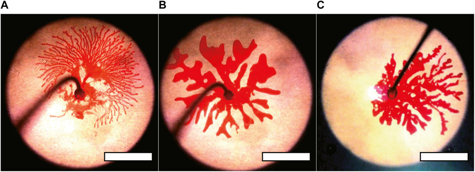
FIGURE 3. (A–C) Snapshots of the fingering pattern for Q = 9.0 mL/min. At the point the inner fluid reached the edge of the outer fluid. The upper, bottom, and both surfaces were coated with fluorine in (A–C), respectively. The fingering pattern was unchanged when the fluorine coat was only applied to the upper plate. Scale bar: 50 mm. Here, we used the outer fluids, the aqueous mixture of CTAB and NaSal mixture with almost identical concentration but with G = 13 Pa and τ = 8 s.
We then examined the characteristics of the fingering dynamics by the image analysis. In Figure 4A, we present snapshots of the injection dynamics with Q = 9.0 mL/min. The transition in the fingering pattern can be observed in Figure 4Aii. We obtained the apparent area S of the inner fluid (Figure 4B) and the estimated average height of injected fluid was obtained from have = Qt/S. We also extracted the time evolution dS/dt, as shown in Figure 4C.
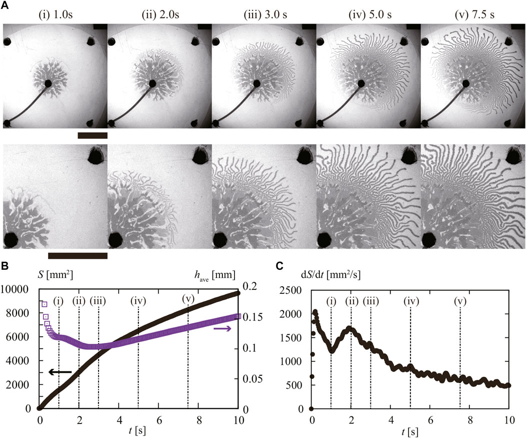
FIGURE 4. (A) Snapshots of observed injection pattern with Q = 9.0 mL/min. From 1 to 2 s (i)–(ii), we observed initially thick fingers, and then after 2 s (ii), thin fingers appeared during the injection. The scale bar corresponds to 50 mm. Time evolution of (B) area S (black) and estimated height of the injected fluid have (purple) for t. The appearance of the (C) time change of area velocity dS/dt. Each number corresponds to the same as in panel (A).
Before t = 1 s corresponding to Figure 4Ai, dS/dt took an initial peak, where we observed the extension of thick fingers. Considering the existence of time lag in the injection, the observed peak and the subsequent decrease in dS/dt before t = 1 s reflect the relaxation of excess injection pressure. Although a stepping motor controlled the constant injection rate at the syringe pump, the rigidity of both the tube and syringe can lead to fluctuation in the pressure of the inner fluid during this initial stage. The initiation of the fluid injection can require relatively high pressure to overcome the Laplace pressure. We also note that the average height of the fluid have took a plateau value of around 0.12 mm.
The graph in Figure 4Aii shows another peak in dS/dt around t = 2 s, which is when thin fingers appear. At this point, the average height have also decreases, reaching a minimum value of around 0.1 mm. These findings indicate a qualitative difference between the formation of thick and thin fingers. The second peak in dS/dt at t = 2 s suggests that the wetting of fluid on the substrate can assist in the formation of thin fingers.
To further characterize the pattern of the thin fingers, we focus our attention on the dynamics of the front of the advancing fingers. To do this, we took a temporal difference of the images that were separated by a time interval of Δt = 0.3 s (D-Image). D-Image allowed us to extract snapshots of the advancing fronts from sequential images (Figure 5A). For the image analysis, we used the data 3 s after the start of the injection. We detected and traced the spot larger than 0.035 mm2. The spot traced more than 1/3 s was considered as the tip of filaments. With this data, we obtained the speed for each extending filament vt. The normalized distribution of vt, ϕ(vt), for Q = 1.0–9.0 mL/min is shown in Figure 5B. Here, ϕ(vt) is normalized such that ∫ϕ(vt)dvt = 1. We then used the dame data for detecting the typical distance between neighboring pairs of advancing fingers ℓ (Figure 5C).
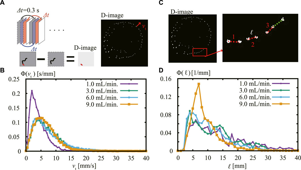
FIGURE 5. (A) Schematic representation of analysis method used with difference image (D-image) where the time interval of Δt = 0.3 s was taken. (B) Normalized distribution of the distance vt of moving fingers for different values of Q. When Q = 3.0–9.0 mL/min, there is a peak at 5 mm/s, whereas the peak is at smaller vt around 2.5 mm/s in the case of Q = 1.0 mL/min. (C) Schematic representation of analysis method used to find the typical distance ℓ between the fingers front. We measured the distance between nearest-neighbor pairs of active fingers connected by colored lines. (D) Normalized distribution of the distance ℓ between the active fingers for different values of Q. When Q = 1.0–6.0 mL/min, there is a peak in the typical distance around 4 mm, while the peak slightly shifted to 7 mm at Q = 9.0 mL/min.
The normalized distribution of distance ϕ(ℓ) for Q = 1.0–9.0 mL/min is shown in Figure 5D. Here, ϕ(ℓ) is normalized such that ∫ϕ(ℓ)dℓ = 1. The distribution of ϕ(ℓ) is almost the same for Q = 1.0–6.0 mL/min, with a peak at 4 mm. The distribution for Q = 9.0 mL/min also displays a peak, but the position has shifted to a longer distance of 7 mm.
In our system, we injected an organic liquid into a cell filled with a viscoelastic fluid, which resulted in the formation of thick and thin fingers. Based on the data we have obtained, we summarize the assumed geometry of these fingers in Figure 6. Here, we suggest that thin fingers should be related to the delamination of outer fluid from the bottom substrate. Initially, the inner fluid causes the bulk fracture of the outer fluid, resulting in thicker fingers. Once the inner fluid reaches the bottom substrate, it starts to delaminate the outer fluid from the bottom substrate, causing thinner fingers.
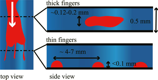
FIGURE 6. Schematic illustration of the thick and thin fingers. Thick fingers appear in the initial stage while fracturing the outer fluid. Thin fingers extend while wetting the bottom surface.
Our interpretation is based on the results, where the thin finger was affected by the fluorinated coating of the bottom plate and changed into thick fingers, as shown in Figure 3. This result can be explained by two possibilities: one is the thin finger wet the bottom surface, while the other is the thick one wet the bottom surface. However, based on a previous study on the wetting of elastic film, we can partially justify the above idea: the thin finger is caused by the delamination process. In that study [29], they examined the adhesion of an elastic film to a rigid substrate in the air. As the elastic film gradually adhered to the substrate, the main fraction of air that was initially present was expelled from the surface, leaving a fingering pattern with a typical distance of λc = 4h, where h corresponds to the thickness of the elastic layer.
Our current study involves injecting oil between the viscoelastic material and the rigid substrate, but it shares similarities with the previous study in that a fluid interacts with a confined elastic layer. In our case, the gap width corresponds to the thickness of the elastic outer fluid, which is 0.5 mm. Therefore, the repeat distance should be λc = 2.0 mm, which is at the same order as the peak observed in Figure 5D for Q = 1.0–9.0 mL/min.
We can further support the idea by inspecting the dynamics of the finger extension shown in Figure 4. According to our assumption, the thin finger is attributed to the delamination; the thin finger extension should be enhanced by the wetting of the surface. Indeed, we found an abrupt increase in dS/dt around 2 s (Figure 4Aii), where we found the appearance of thin fingers as seen in Figure 4C.
To summarize, the present results show that the injection of an incompressible viscous fluid into a viscoelastic fluid produces fingers. Two types of fingers were observed–thick and thin, as shown in Figure 6. Thick fingers appear initially and are likely related to bulk fracture formation, which is insensitive to the wetting of the surface. Thin fingers appear later and correspond to the delamination process, where the distance between fingers should be approximately four times the cell depth. Both the delamination process and bulk fracture formation are typical of elastic films. This study reveals that the wettability of a fluid can affect the injection behavior significantly, especially in the case that the injected materials were confined in the other hard substrate. This situation is commonly observed in the industrial and geophysical environment.
Our study focuses on exploring the behavior of viscoelastic materials in a Hele-Shaw cell, which can help simulate engineering and geophysical environments. Specifically, we examined the fingering pattern dynamics of a wormlike micellar solution, which was used as an outer viscoelastic fluid in a cell. We used an incompressible viscous liquid, tetradecane stained with oil red, as the inner fluid. The inner fluid was injected from the center of the cell at a fixed rate Q, which was chosen to ensure that the outer fluid behaved elastically with slow relaxation, allowing for the injection of fluid irreversibly.
After injecting the inner fluid, we observed a fingering pattern. We observed the different fingering patterns characterized by thick and thin fingers. It is worth noting that the results of our study differ from previous observations of viscoelastic fingering, which mainly focused on the transition of material viscoelasticity. In those cases, the transition from viscous to elastic behavior would eventually lead to the formation of bulk fractures, as previously reported in studies [30, 31]. These fingering do not depend on the surface’s wettability. In our study, however, the thin fingers were sensitive to the coating of the bottom plate. The contact angle measurements suggest that the bottom plate was highly wettable to the inner fluid. Based on these observations, we suggest that the delamination of the outer viscoelastic fluid from the bottom surface contributed to the formation of thin fingers. This difference is mainly attributed to using organic inner and aqueous outer fluids with the oleophilic resin as a substrate. Combining these material properties resulted in the inner fluid preferring the bottom surface, which led to the delamination process. This assumption may be confirmed by the three-dimensional analysis of fingers, but technical difficulties make this analysis a future study.
Our research has shown that modifying the interfacial energy of the substrate surface through chemical treatment can impact fingering behavior. Our sample has a long rheological relaxation time, which made the injection proceed essentially in the elastic regime. However, the wetting of fluid on a surface, which is typically the character of fluid, played an essential role in the fingering process. Thus, our study can be recognized as a type of elastocapillary problem [32]. Our findings are relevant to the injection of fluids into soil even when the injected material behaves as solids. We should note that soil can behave as elastic and is an inhomogeneous surface that is both chemically and geometrically diverse. On this account, further studies could explore how quenched disorder of wetting properties affects fingering dynamics in the elastic environment.
The raw data supporting the conclusion of this article will be made available by the authors, without undue reservation.
KY: Conceptualization, Data curation, Formal Analysis, Investigation, Methodology, Software, Visualization, Writing–original draft, Writing–review and editing. KO: Data curation, Formal Analysis, Writing–original draft, Writing–review and editing, APS: Data curation, Formal Analysis, Writing–original draft, Writing–review and editing. YS: Conceptualization, Data curation, Formal Analysis, Funding acquisition, Investigation, Methodology, Project administration, Resources, Software, Supervision, Visualization, Writing–original draft, Writing–review and editing.
The author(s) declare financial support was received for the research, authorship, and/or publication of this article. This work was supported by JSPS KAKENHI Grant Nos. JP16K13866, JP16H06478, JP19H05403, JP21H00409, and JP21H01004. This work was also partially supported by a JSPS Bilateral Joint Research Program between Japan and the Polish Academy of Sciences, “Spatio-temporal patterns of elements driven by self-generated, geometrically constrained flows,” and the Cooperative Research of the “Network Joint Research Center for Materials and Devices” with Hokkaido University (No. 20181048).
The authors would like to thank S. Wagatsuma (Tokyo Univ. Sci.) for his help in constructing the experimental setups at the beginning of this research.
The authors declare that the research was conducted in the absence of any commercial or financial relationships that could be construed as a potential conflict of interest.
All claims expressed in this article are solely those of the authors and do not necessarily represent those of their affiliated organizations, or those of the publisher, the editors and the reviewers. Any product that may be evaluated in this article, or claim that may be made by its manufacturer, is not guaranteed or endorsed by the publisher.
1. Nicolis G, Prigogine I. Self-organization in nonequilibrium systems: from dissipative structures to order through fluctuations. Wiley (1977).
2. Homsy GM. Viscous fingering in porous media. Ann Rev Fluid Mech (1987) 19:271–311. doi:10.1146/annurev.fl.19.010187.001415
3. De Wit A, Bertho Y, Martin M. Viscous fingering of miscible slices. Phys Fluids (2005) 17:054114. doi:10.1063/1.1909188
4. Haudin F, Cartwright JHE, Brau F, De Wit A. Spiral precipitation patterns in confined chemical gardens. Proc Natl Acad Sci USA (2014) 111:17363–7. doi:10.1073/pnas.1409552111
5. Wagatsuma S, Higashi T, Sumino Y, Achiwa A. Pattern of a confined chemical garden controlled by injection speed. Phys Rev E (2017) 95:052220. doi:10.1103/PhysRevE.95.052220
6. Shukla P, De Wit A. Fingering dynamics driven by a precipitation reaction: nonlinear simulations. Phys Rev E (2016) 93:023103. doi:10.1103/PhysRevE.93.023103
7. Tanaka S, Otoguro K, Kunihiro M, Ishikawa H, Sumino Y. Precipitation induced filament pattern of injected fluid controlled by structured cell. Arxiv 2308.15086 (2023)
8. Mishra M, Martin M, De Wit A. Influence of miscible viscous fingering of finite slices on an adsorbed solute dynamics. Phys Fluids (2009) 21:083101. doi:10.1063/1.3200870
9. Chui JY, De Anna P, Juanes R. Interface evolution during radial miscible viscous fingering. Phys Rev E (2015) 92:041003–5. doi:10.1103/PhysRevE.92.041003
10. Obara K, Kato A. Connecting slowearthquakes to huge earthquakes. Science (2016) 353:253–7. doi:10.1126/science.aaf1512
11. Ujiie K, Saishu H, Fagereng U, Nishiyama N, Otsubo M, Masuyama H, et al. An explanation of episodic tremor and slow slip constrained by crack-seal veins and viscous shear in subduction melange. Geophys Res Lett (2018) 45:5371–9. doi:10.1029/2018gl078374
12. Suzuki T, Yamashita T. Effects of shear heating, slip-induced dilatancy and fluid flow on diversity of 1-D dynamic earthquake slip. J Geophys Res Solid Earth (2014) 119:2100–20. doi:10.1002/2013jb010871
13. Tanaka Y, Suzuki T, Imanishi Y, Okubo S, Zhang X, Ando M, et al. Temporal gravity anomalies observed in the tokai area and a possible relationship with slow slips. Earth, Planets and Space (2018) 70:25. doi:10.1186/s40623-018-0797-5
14. Hirata T. Fracturing due to fluid intrusion into viscoelastic materials. Phys Rev E (1998) 57:1772–9. doi:10.1103/PhysRevE.57.1772
15. Zhao H, Maher JV. Associating-polymer effects in a hele-shaw experiment. Phys Rev E (1993) 47:4278–83. doi:10.1103/PhysRevE.47.4278
16. Saintyves B, Mora S, Bouchaud E. A meniscus fingering instability in viscoelastic fluids. Phys Fluids (2019) 31:063108. doi:10.1063/1.5097685
17. Hue SH, Chagot L, Angeli P. Viscoelastic effects of immiscible liquid–liquid displacement in microchannels with bends. Phys Fluids (2022) 34:073111. doi:10.1063/5.0091501
18. Rodrigues RK, da Silva MA, Sabadini E. Worm-like micelles of CTAB and sodium salicylate under turbulent flow. Langmuir (2008) 24:13875–9. doi:10.1021/la802890x
19. Anh Tuan N, Mizunuma H. Advection of shear-induced surfactant threads and turbulent drag reduction. J Rheology (2013) 57:1819–32. doi:10.1122/1.4826543
20. Shikata T, Hirata H, Kotaka T. Micelle formation of detergent molecules in aqueous media: viscoelastic properties of aqueous cetyltrimethylammonium bromide solutions. Langmuir (1987) 3:1081–6. doi:10.1021/la00078a035
21. Shikata T, Hirata H, Kotaka T. Micelle formation of detergent molecules in aqueous media. 2. Role of free salicylate ions on viscoelastic properties of aqueous cetyltrimethylammonium bromide-sodium salicylate solutions. Langmuir (1988) 4:354–9. doi:10.1021/la00080a019
22. Gladden JR, Belmonte A. Motion of a viscoelastic micellar fluid around a cylinder: flow and fracture. Phys Rev Lett (2007) 98:224501. doi:10.1103/PhysRevLett.98.224501
23. Sumino Y, Shibayama H, Yamaguchi T, Kajiya T, Doi M. Failure of film formation of viscoelastic fluid: dynamics of viscoelastic fluid in a partially filled horizontally rotating cylinder. Phys Rev E (2012) 85:046307. doi:10.1103/PhysRevE.85.046307
24. Handzy NZ, Belmonte A. Oscillatory rise of bubbles in wormlike micellar fluids with different microstructures. Phys Rev Lett (2004) 92:124501. doi:10.1103/PhysRevLett.92.124501
25. Schneider CA, Rasband WS, Eliceiri KW. NIH Image to ImageJ: 25 years of image analysis. Nat Methods (2012) 9:671–5. doi:10.1038/nmeth.2089
26. Hu Y, Rajaram CV, Wang SQ, Jamieson AM. Shear thickening behavior of a rheopectic micellar solution: salt effects. Langmuir (1994) 10:80–5. doi:10.1021/la00013a012
27. Inoue T, Inoue Y, Watanabe H. Nonlinear rheology of CTAB/NaSal aqueous solutions: finite extensibility of a network of wormlike micelles. Langmuir (2005) 21:1201–8. doi:10.1021/la048292v
28. Bird RB, Armstrong RC, Hassager O. Dynamics of polymeric liquids. Fluid Mechanics (1987). Wiley-Interscience 1:258.
29. Ghatak A, Chaudhury MK. Adhesion-induced instability patterns in thin confined elastic film. Langmuir (2003) 19:2621–31. doi:10.1021/la026932t
30. Mora S, Manna M. Saffman-Taylor instability of viscoelastic fluids: from viscous fingering to elastic fractures. Phys Rev E (2010) 81:026305. doi:10.1103/PhysRevE.81.026305
31. Lemaire E, Levitz P, Daccord G, Van Damme H. From viscous fingering to viscoelastic fracturing in colloidal fluids. Phys Rev Lett (1991) 67:2009–12. doi:10.1103/PhysRevLett.67.2009
Keywords: viscoelastic fluid, injection, delamination, fingering, wormlike micellar solution
Citation: Yoshii K, Otoguro K, Sato AP and Sumino Y (2024) Extensive tip-splitting of injected organic liquid into an aqueous viscoelastic fluid. Front. Phys. 12:1332187. doi: 10.3389/fphy.2024.1332187
Received: 02 November 2023; Accepted: 11 January 2024;
Published: 01 February 2024.
Edited by:
Pawan Kumar, Indian Institute of Technology Kanpur, IndiaReviewed by:
Bruno Batista, Florida State University, United StatesCopyright © 2024 Yoshii, Otoguro, Sato and Sumino. This is an open-access article distributed under the terms of the Creative Commons Attribution License (CC BY). The use, distribution or reproduction in other forums is permitted, provided the original author(s) and the copyright owner(s) are credited and that the original publication in this journal is cited, in accordance with accepted academic practice. No use, distribution or reproduction is permitted which does not comply with these terms.
*Correspondence: Yutaka Sumino, eXN1bWlub0Bycy50dXMuYWMuanA=
†Present address: Kiwamu Yoshii, Department of Physics, Nagoya University, Aichi, Japan
Disclaimer: All claims expressed in this article are solely those of the authors and do not necessarily represent those of their affiliated organizations, or those of the publisher, the editors and the reviewers. Any product that may be evaluated in this article or claim that may be made by its manufacturer is not guaranteed or endorsed by the publisher.
Research integrity at Frontiers

Learn more about the work of our research integrity team to safeguard the quality of each article we publish.