
95% of researchers rate our articles as excellent or good
Learn more about the work of our research integrity team to safeguard the quality of each article we publish.
Find out more
ORIGINAL RESEARCH article
Front. Phys. , 09 May 2024
Sec. Medical Physics and Imaging
Volume 12 - 2024 | https://doi.org/10.3389/fphy.2024.1323788
This article is part of the Research Topic Development of Task Specific Phantoms and Test Objects for Medical Imaging View all 8 articles
 Jacob Brunner1,2*
 Lorenz Langgartner1,2
 Hannah Danhel1
 Wolfgang Birkfellner3
 Christian Richter4,5,6Dirk Wagenaar7
 Markus Stock2,8
 Dietmar Georg1,2
 Barbara Knäusl1,2
Objective: 3D printing has seen use in many fields of imaging and radiation oncology, but applications in (anthropomorphic) phantoms, especially for particle therapy, are still lacking. The aim of this work was to characterize various available 3D printing methods and epoxy-based materials with the specific goal of identifying suitable tissue surrogates for dosimetry applications in particle therapy.
Methods: 3D-printed and epoxy-based mixtures of varying ratios combining epoxy resin, bone meal, and polyethylene powder were scanned in a single-energy computed tomography (CT), a dual-energy CT, and a µCT scanner. Their CT-predicted attenuation was compared to measurements in a 148.2 MeV proton and 284.7 MeV/u carbon ion beam. The sample homogeneity was evaluated in the respective CT images and in the carbon beam, additionally via widening of the Bragg peak. To assess long-term stability attenuation, size and weight measurements were repeated after 6–12 months.
Results: Four 3D-printed materials, acrylonitrile butadiene styrene polylactic acid, fused deposition modeling printed nylon, and selective laser sintering printed nylon, and various ratios of epoxy-based mixtures were found to be suitable tissue surrogates. The materials’ predicted stopping power ratio matched the measured stopping power ratio within 3% for all investigated CT machines and protocols, except for µCT scans employing cone beam CT technology. The heterogeneity of the suitable surrogate samples was adequate, with a maximum Bragg peak width increase of 11.5 ± 2.5%. The repeat measurements showed no signs of degradation after 6–12 months.
Conclusion: We identified surrogates for soft tissue and low- to medium-density bone among the investigated materials. This allows low-cost, adaptable phantoms to be built for quality assurance and end-to-end tests for particle therapy.
Producing tissue surrogate materials to mimic the radiation attenuation of patient tissue for radiotherapy has been investigated since the seventies. A comprehensive characterization of the elemental composition of human tissues [1] and the ICRU report 44 on “Tissue Substitutes in Radiation Dosimetry” are the foundation of modern surrogates [2]. Potential candidates to expand or improve the material library are investigated to this day [3–6].
Phantoms made from such tissue surrogate materials are used for quality assurance (QA), commissioning, and dosimetric end-to-end (E2E) tests [7]. They come in various shapes suitable for their purpose [8–10], from simple geometric solids to complex anthropomorphic phantoms. Particularly, anthropomorphic phantoms used in E2E tests need to fulfill all conditions that will be considered during imaging, treatment planning, and dosimetry following well-established procedures.
Because the attenuation properties of charged particles depend on the elemental composition, tissue surrogates and phantoms designed for photon radiation are not inherently suitable for particle therapy (PT). Commercial solutions for PT exist, but they provide limited capability to mimic workflows beyond clinical standards. These specialized and novel treatment strategies, such as adaptive PT, compensate for patient weight loss, as one example. Their workflows require efficient QA procedures employing dedicated phantoms, which are currently lacking when it comes to clinical implementation [11].
To overcome this limitation, QA solutions for novel workflows are machined from slabs of well-characterized surrogate materials [12, 13] or use conventional phantoms modified, for example, by drilling holes to access the nasal cavities and change their filling [14]. On the other hand, additive manufacturing (AM), more commonly known as 3D printing, has gained traction as a way to enable quick and economical production of phantom components [15–17]. In recent years, commercial solutions for individualized, 3D-printed phantoms for photon therapy have entered the market [18, 19], but their transferability to particle application is limited [20].
Because most AM materials are polymer-based, their elemental composition differs from tabulated human tissues. Thus, dosimetric characterization is required to assess their suitability as tissue surrogates. Therefore, various 3D printing methods and materials were investigated with respect to their ability to mimic common tissue types for PT, such as soft tissue, cartilage, and bone.
The aim of this work was to identify 3D printing materials suitable for manufacturing a phantom suitable for dosimetric E2E tests and QA purposes in PT. For all investigated materials, the size and weight after print, CT number (CTN), water equivalent thickness (WET), Bragg peak (BP) width, constancy of material properties and the prediction accuracy of stopping power ratio (SPR) with different scan protocols, or computed tomography (CT) scanners were evaluated.
In-house sample production used fused deposition modeling (FDM) (FUNMAT PRO 410, INTAMSYS, China)—a widely available and affordable 3D printing method—and stereolithography (SLA) (Form 3, Formlabs, United States). SLA inherently prints more homogeneous samples but is more expensive and, by that, less common than FDM. The selective laser sintering (SLS) (FORMIGA P110, EOS, Germany) method was chosen additionally as a method that was more precise than FDM and could print complex geometries without support structures. SLS samples were produced by an external company (PROTIQ, Germany).
A total of nine different 3D-printed materials were investigated. Materials with different densities were chosen to imitate human tissue types from soft tissue to bone. Reference human tissues are tabulated in Supplementary Material 1A [1]. An overview of the investigated materials, their density, and corresponding printing technique is provided in Table 1. The exact chemical compositions were not available. According to the manufacturer, the “Nylon” samples, FDM-printed Nylon 6/66 (NY-FDM) and SLS-printed PA2200 (NY-12), are based on polyamide 6/66 and polyamide 12, respectively.
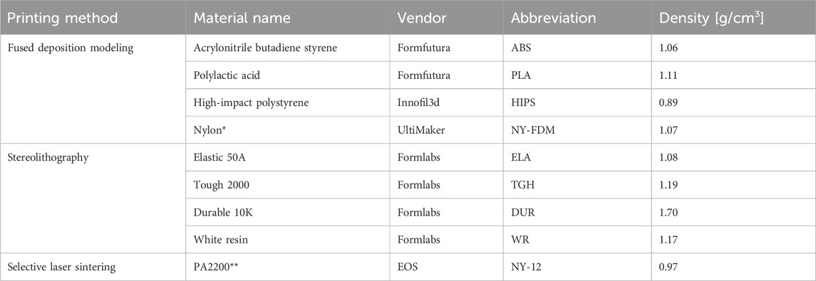
Table 1. Overview of 3D printing techniques and materials. The column 'Vendor' refers to the vendor of the material, not the 3D printing machine. *according to the manufacturer, based on polyamide 6/66; **according to the manufacturer, based on polyamide 12.
All samples were printed as 5 cm3 × 5 cm3 × 1 cm3 cuboids for experimental WET analysis in a particle beam. For the CTN analysis, cylinders of 3 cm diameter and 5 cm length were printed to be used in a CIRS electron density phantom (CIRS, United States). Example prints of all used printing methods are shown in Supplementary Figure S1B.
In addition to the 3D-printed materials, bone surrogate samples were produced based on bisphenol A/F resin with a cycloaliphatic polyamine hardener, further called epoxy-based samples. Various mixtures of epoxy resin (ER) ( “Resin L” + “Hardener S”; R&G Composite Materials, Germany), bone meal (BM) (“all-natural bone meal”; Grau, Germany) and polyethylene powder (PE) (HDPE Coathylene NB 5374-F, Axalta, United States) were manufactured in-house. The ratio of the ER was kept constant at a 50% mass fraction; only the ratio of BM to PE was varied. An abbreviation for mixtures was introduced as parts of ER:BM:PE; for example, the abbreviation is 2:1:1 for 50% ER, 25% BM, and 25% PE. The PE was added for two purposes: decreasing the density of the material to mimic lower-density bone and to aid the miscibility of the powder to the resin. The samples were cast to the same shape and dimensions as the 3D-printed samples shown in Supplementary Figure S1B. After curing for 24 h, the casts were removed from 3D-printed molds and could be characterized. For the 1:1:0 ER:BM:PE and 5:4:1 ER:BM:PE mixtures, three samples were produced each and used for further experiments. The 2:1:1 ER:BM:PE and 5:1:4 ER:BM:PE samples were considered unsuitable after the first batch and, thus, not replicated.
The beam attenuation of all samples was determined experimentally in a 148.2 MeV proton beam and a carbon beam with 284.7 MeV/u using the PeakFinder (PTW, Germany). Each time the experiment was set up, the particle range in water was acquired as a baseline. To assess homogeneity, the measurements were taken through three points of the sample and repeated three times for a total of nine measured depth dose curves. The WET was calculated according to Eq. (1):
where r80,water is the distal 80% depth of the BP in water and r80,sample is the distal 80% depth of the BP with the sample in the beam path acquired using the identical measurement setup.
The SPRmeas was determined according to Eq. (2):
where t is the thickness of the sample that was traversed by the particle beam.
A larger number of interfaces introduced by heterogeneous materials increase range straggling and, by that, the BP width. Therefore, the BP width of the samples in the beam path was investigated by calculating the difference between the distal and proximal r80 of the depth dose curve. The BP width of water served as the baseline.
The lateral profile after passing through the samples was investigated by placing Gafchromic EBT3 films (Ashland Global Holdings Inc., Delaware, United States) perpendicular to the beam direction. A qualitative assessment was performed by summing up the three color channels and subtracting the lateral profile of the water baseline. The different samples’ WET was taken into account by positioning the EBT3 films 50 mm in front of the respectively shifted r80.
All samples were stored at ambient temperature and humidity in a dark environment. Repeat measurements of mass, dimensions, and attenuation were performed after 1 year for the 3D-printed samples and after 6 months for the resin-based samples.
To determine the SPR directly, dual-energy CT (DECT) scans were performed on a single-source CT scanner SOMATOM Definition AS transforming CT numbers voxelwise into an SPR using the DirectSPR approach (Siemens Healthineers, Germany), further referred to as ‘DirectSPR’. Detailed scan settings are given in Table 2 [21, 22].
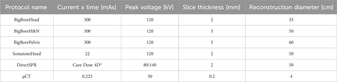
Table 2. Overview of the scan parameters used for SECT, DECT, and µCT scans. *The “Care Dose 4D” option uses an adaptive current; reconstruction algorithm “Q40f/3” (Safire at medium strength), see [21].
Prediction accuracy can vary across European centers even for standard materials [23]. Thus, we assessed the SPR prediction accuracy of the materials on multiple single-energy CT (SECT) scanners and protocols to eliminate systematic errors. SECT scans were performed on a Big Bore CT scanner (Philips, Netherlands) and a SOMATOM Confidence (Siemens Healthineers, Germany) using the clinical scan settings given in Table 2. All scan protocols at the Big Bore CT scanner had fixed settings, while the SomatomHead protocol worked with variable mAs depending on the patient’s dimensions. For each set of scan settings, a corresponding Hounsfield unit lookup table (HLUT) was used [24]. The cylindrical material samples were contoured as regions of interest (ROIs) in the treatment planning system (TPS) with a radius of 1.2 cm and 3 cm length to avoid edge effects. The CTN distributions were extracted (see Supplementary Figure S1B) to determine the predicted SPR (SPRpred) employing the validated, scan-specific HLUT [25, 26].
As the flexibility of 3D printing for phantoms and other equipment is particularly interesting for preclinical research [15], we additionally investigated the SPR prediction employing µCT scans (X-CUBE, Molecubes, Belgium). For scan settings, see Table 2. Due to the characteristic configuration of the µCT employing cone beam CT (CBCT) technology, a separate HLUT used for preclinical purposes was employed.
SPRmeas and SPRpred were collected in an identical manner for the epoxy resin-based and 3D-printed samples, respectively.
The comparison between SPRmeas and SPRpred was quantified using Eq. (3):
where a difference to agreement (DTA) of 0% would mean perfect agreement. A DTA of <3% was considered an acceptable tissue substitute because this is within the common range of uncertainty in particle therapy [27, 28]. DTA uncertainty was derived by propagating type A uncertainties from SPRpred and SPRmeas.
For WET measurements, the standard deviation (SD) of three repetitions for three points per sample (total of nine r80 per sample) was calculated. Accordingly, reported SPRmeas values were derived from these averages. The SDs of the measured WET and t values were estimated as type B uncertainties of 0.1 mm and were propagated as the uncertainty of SPRmeas.
Reported values of CTN were given as the mean and SD of said CTN distributions. The SPRpred was derived by calculating the SPR from the CTN as implemented into the TPS (RayStation 11B-R, RaySearch, Sweden). The reported SPRpred values were the mean and SD of the derived distributions.
The homogeneity of the samples was heavily reliant on the printing techniques and parameters. For FDM prints, the manufacturer’s recommended settings with a slow printing speed of 30 mm/min and 100% infill and a zig-zag pattern were used to achieve satisfactory results. The acrylonitrile butadiene styrene (ABS) printing parameters needed to be refined to 90°C platform temperature, 80°C chamber temperature, 260°C printing temperature, a 0.4 mm diameter extruder, and 50% fan speed in order to achieve the best results. For the homogeneity of the SLA prints, no dependency on the height of layers in the z-direction (options of 50 µm and 100 μm; the latter was used for final samples) was observed; the other SLA parameters were standard manufacturer settings. The resin-based samples were manufactured by first carefully stirring the powder into the resin to avoid air inclusions. After the powder and resin mixture was deemed homogeneous, the hardener was stirred in last and for no more than 5 min. After 5 min, the viscosity increased to a degree where pouring the mixtures into a mold resulted in an increase of air pockets. The bone meal acted as an undesired catalyst and led to uncontrolled curing and excess heat. Thus, for the first 4–5 h of curing, a cold environment was assured (approximately 4°C) to dissipate the heat. Applying lab shakers and a vacuum led to adverse results because the cooling during those processes was insufficient. After 24 h, the curing process was complete. At PE weight fractions higher than 25%, mixing was considerably impaired, and large air bubbles were entrapped in the mixtures, as seen in Table 3.
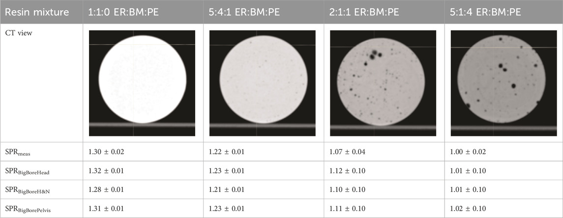
Table 3. Examples of material homogeneity of epoxy resin-based mixtures. SECT scans were performed with the BigBoreHead protocol. Relative polyethylene powder content increases from left to right. The two rightmost samples show visible air inclusions. SPR values are mean and one SD.
Remeasuring size and weight after 1 year/6 months showed differences <0.5% for all material types. The data are recorded in Supplementary Figure S1C.
The average difference between carbon and proton WET was 0.6 ± 0.8% for all investigated samples, which was within the range of measurement accuracy. Unless further specified, subsequent results shown as SPRmeas refer to proton measurements. For all samples, the WET stayed within 1% when repeating the measurements described in Section 2.4.
The proton BP width of 4.1 ± 0.1 mm in water experienced a maximum broadening of the BP by 11.2 ± 1.8% for high-impact polystyrene (HIPS). By visual inspection of the CT images, HIPS was the most heterogeneous material. For most of the materials, the heterogeneity increased the BP width by less than 5%.
The BP width of the carbon beam was evaluated with the baseline for water and was found to be 2.4 ± 0.1 mm. An increase in BP was not observed for the SLA prints. The SLS print led to a BP width increase of 2.5 ± 0.6%. For the group of FDM prints, the BP width fluctuated with an average increase of 14.1 ± 10.1%. Inhomogeneous samples, such as HIPS, strayed farther from the baseline than, for example, NY-FDM (2.1 ± 2.9%) or polylactic acid (PLA) (11.5 ± 2.3%). The resin-based casts with a PE content of less than 10% mass showed an average BP width increase of 12.6 ± 3.5%. The BP width was not reported for the resin-based samples with a PE content larger than 10% mass, as the heterogeneity of the high PE samples led to severe degradation of the BP at some points, as seen in Figure 1.
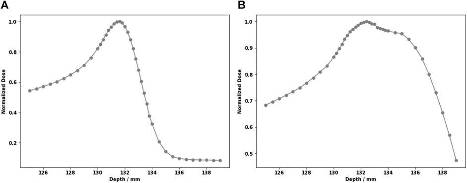
Figure 1. Large heterogeneities in the high-PE samples lead to Bragg peak degradation. For two points through the 2:1:1 sample. (A) Clean Bragg peak; (B) severely degraded peak.
A qualitative assessment of the lateral beam profile difference maps after passing through the 3D-printed samples did not show any systematic difference that would be associated with an increased lateral scatter. An example of the analysis and the background signal of such a measurement is shown in Supplementary Figure S1D.
The DECT-based predicted SPR (DirectSPR algorithm) agreed well with measurements. DirectSPR prediction revealed an average absolute DTA of 1.6 ± 1.5% for 3D-printed and 0.7 ± 0.9% for resin-based materials. The only samples where the DTA exceeded 3% were HIPS and Durable 10K (DUR), with DTAs of 3.3 ± 4.4% and -4.6 ± 2.0%, respectively. An example comparison of the SPRDirectSPR distribution with SPRmeas and SPRBigBorePelvis is illustrated in Figure 2. All nominal SPR values are provided in Supplementary Figure S1E.
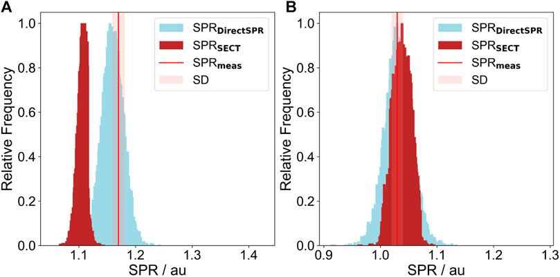
Figure 2. Comparison between the SECT-based SPRBigBorePelvis distribution (brown) and the SPRDirectSPR (blue). The SPRmeas is marked by a red line; the light red confidence interval has a total width of two σ. (A) White resin (WR); (B) ABS.
The CTNs for most of the 3D-printed materials ranged from −200 HU to 200 HU for the BigBoreHead protocol. The only value outside that interval was DUR, with an average CTN of 753 ± 11 HU. The behaviors of the predicted SPRBigBoreHead and comparisons to the measurements are shown in Figure 3. The average absolute DTA for the SPRBigBoreHead was 4.8 ± 3.2% the 3D-printed samples. The SPRpred values for the nine 3D-printed materials are summarized in Table 4 for all scan protocols. Figure 4 illustrates the dependency of DTA per material on the scan parameters used. The DTA of the materials NY-12, ABS, NY-FDM, and PLA was <3% for all scans. They are marked in bold in Table 4 and in light blue in Figure 3. Comparing the different protocols for each material, a maximum disagreement of 1.4% DTA was found for NY-12, ABS, NY-FDM, and PLA. The other materials exhibited a maximum disagreement of 3.5% DTA, illustrated in Figure 4 looking at DUR as an example. An example of a SECT distribution compared with a DirectSPR prediction is displayed in Figure 2.
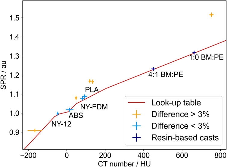
Figure 3. CTN to SPRpred for the BigBoreHead protocol. The length of the error bars is one standard deviation; the brown curve represents the commissioned HLUT. The 3D-printed materials with a DTA >3% are marked in yellow, and those with a DTA <3% are marked in light blue. Only the resin-based materials with a DTA <3% are plotted; they are colored in dark blue.
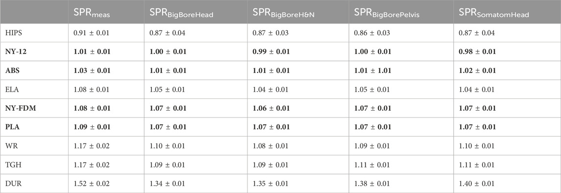
Table 4. Summary comparison between SPRpred and SPRmeas for two CT scanners and calibration curves. The bold rows mark materials with a DTA <3% in all scan protocols, as seen in Figure 4. Mean and one standard deviation are presented.
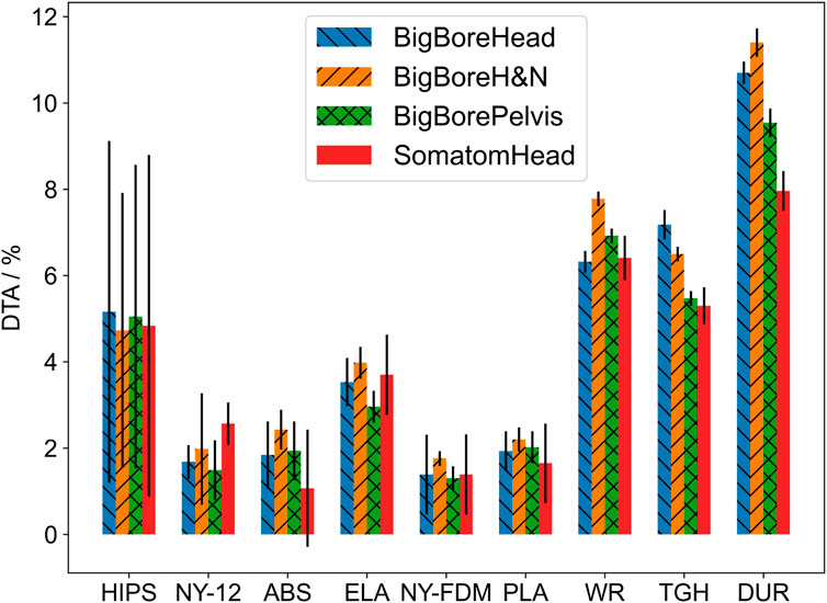
Figure 4. Prediction errors for various SECT protocols. For each CT scan, the DTA from SPRpred to SPRmeas is compared. Error bars represent one SD. The samples with a low DTA show more consistency between protocols than the samples with a high DTA, that is, Durable 10K.
The CTNs of the epoxy-based materials ranged from 451 ± 12 HU to 638 ± 14 HU for SPRBigBoreHead. Their SPRmeas values ranged from water for the highest PE content to spongeous bone for the intermediate amount of PE. The samples with little to no PE added had an SPR in the range of medium-density bone. The high PE samples with a ratio of ER:BM:PE 2:1:1 and ER:BM:PE 5:1:4 showed a DTA between −3.4 ± 0.9 % and −1.5 ± 0.4 % averaged over all protocols. Large air inclusions were visible in the respective CT scans, which can be seen in Table 3. The low PE samples (ER:BM:PE 1:1:0 and ER:BM:PE 5:4:1) showed a DTA of 1.2 ± 1.2% and -0.6 ± 1.2% for all protocols listed in Table 3. Figure 3 shows the measured values in dark blue, and the SPRBigBoreHead value is shown in brown.
For the µCT scans, the DTA of both 3D-printed and resin-based samples differed by more than 3% from SPRmeas for all materials except NY-FDM with a of 2.5 ± 2.7 %. Figure 5 shows the SPRmeas compared to the SPRpred based on the µCT data. The respective µCT calibration curve depicted in Figure 5 was acquired using the same materials and a similar size-adapted methodology as the SECT BigBore protocols. The biggest contributors to the worse agreement across the board were most likely the systematic differences between the scanner calibrations, that is, the lower energy spectrum (50 kVp vs. 120 kVp) and detector geometry (CBCT vs. fan beam CT).
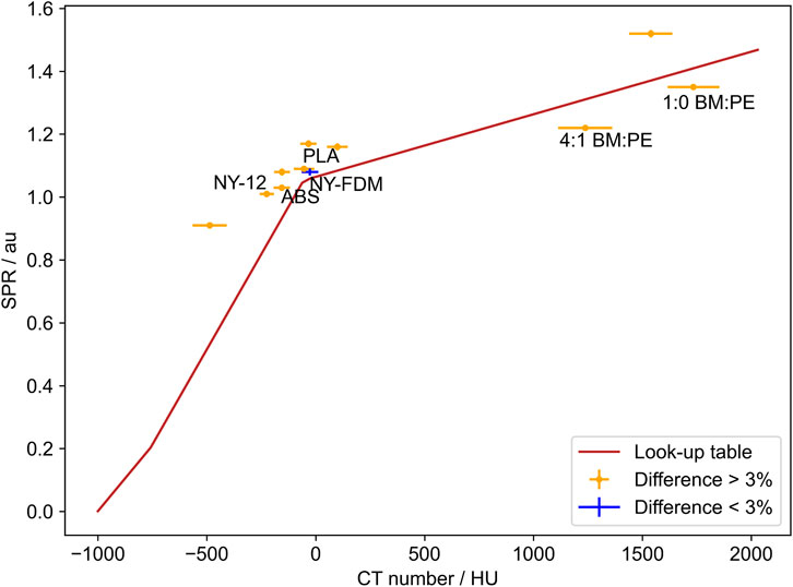
Figure 5. Comparison between SPRpred based on the µCT data and SPRpred. The mean difference of NY-FDM was the only sample with a difference below 3%.
Nine 3D-printed materials were investigated within this project, of which three FDM-printed and one SLS-printed material were considered adequate soft-tissue surrogates. Their SPR was in the relevant range for fatty tissues to cartilage (see Supplementary Material S1A), and the SPRpred assessment was accurate (within 3%) for different CT scanners or imaging protocols.
PT requires excellent 3D printing homogeneity and precision because imperfections will alter the beam attenuation much more than in x-ray-based therapy. Past results have presented shortcomings, such as anisotropic behavior in CT scans [29] or SPR variations within the sample geometry [30]. Still, a few PT applications for 3D-printed (anthropomorphic) phantoms have been presented, and some have reported a mismatch of CT-predicted SPR for the materials used [15, 20]. Furthermore, recent publications have shown good results concerning 3D printing applications for particle beam modulation [31–35].
The BP width assessment revealed visible but acceptable broadening for FDM and SLS prints. In addition to the constant shape of the lateral beam profiles, this is good evidence that the 3D prints do not deteriorate beam quality. Recent findings by Barna et al. further showed that 3D-printed structures even preserved radiation quality on a microdosimetric scale [31]. Overall, the SLA prints were not considered tissue surrogates because of their high SPR and poor prediction accuracy but can be recommended for, for example, patient-specific boluses using a bulk override to avoid reported FDM-printing inaccuracy and heterogeneity [36].
DECT-based attenuation prediction is arguably the gold standard for imaging in PT [37–43]. The SPR prediction using the DirectSPR approach showed average absolute DTAs for all investigated 3D-printed samples that were a factor of three lower than the SECT-based predictions. The SPRpred, DirectSPR exceeded the threshold of 3% only for HIPS and DUR. The below-average printing quality and resulting heterogeneity of HIPS and the unconventional mix of photo-polymer and silicates of DUR most likely caused this deviation [44]. Fine-tuning the printing parameters could alleviate the effect for HIPS. The difference in the width of the SPR distributions between the SECT and DirectSPR approach in Figure 2 is due to the additional noise introduced during the processing of the DirectSPR map. The CTN distribution widths of a pseudo-monoenergetic CT and a SECT were comparable for all samples.
The SECT predictions showed agreement between the various protocols for the surrogate candidates NY-12, ABS, NY-FDM, and PLA. The variation was biggest for DUR due to the large difference in material composition compared to the reference materials used for HLUT generation.
µCT-based SPR prediction was poor, with a DTA of more than 3% for eight of nine samples. A likely explanation for that could be the low energy spectrum of the scanner increasing the relative influence of the photo effect on the total attenuation coefficient. For nuclei with Z/A
Resin-based materials produced with a similar technique were found to be suitable as low to medium-density bone surrogates for imaging purposes [46]. Our results showed they can be used as bone surrogates in proton and carbon ion therapy. Within an interval of 50% to 40% weight of bone meal, the attenuation properties were successfully tuned by adding polyethylene powder. The mixture of only three ingredients made the materials easy to produce. This was combined with 3D printing technology by casting the mixture in molds. However, production limitations made high-density cortical bone and bone structures of more than one density infeasible. Unlike in a recent publication by Cook et al. [6], the goal was not to find materials performing closer to tabulated human tissues [1] than current solutions but rather to reach the level of performance of the tissue surrogates currently used for Hounsfield unit (HU) curve calibration.
Stuchebrov et al. reported that neither mechanical properties nor electron beam attenuation of FDM prints deteriorate with doses up to 1.5 kGy [47]. Our results showed the time stability of the sample properties (e.g., attenuation, weight, and size) make them suitable for manufacturing phantoms, where stable conditions are paramount for safe and effective (long-term) quality assurance. However, it is recommended to store the materials away from exposure to UV light, as this is a major factor in 3D prints degradation [48].
The agreement between proton and carbon ion results underlines that heterogeneity is not a knock-out criterion for 3D printing anthropomorphic phantoms in PT with various ion species. In this study, we could identify materials that can be considered stable, homogeneous, and versatile bone and soft-tissue surrogates for PT applications, complementing the existing data sets of beam-modulating devices [3, 8, 29, 32, 35].
In this study, we dosimetrically characterized various potential tissue surrogates. Major concerns, such as heterogeneity and insufficient long-term stability, were ruled out for all 3D-printed samples and for resin-based mixtures with a PE content <10% mass. The presented materials and methods offer adaptable and affordable 3D-printed alternatives to build dedicated QA phantoms for adaptive PT workflows.
The original contributions presented in the study are included in the article/Supplementary Material; further inquiries can be directed to the corresponding author.
JB: writing–review and editing, writing–original draft, visualization, validation, software, project administration, methodology, investigation, formal analysis, data curation, and conceptualization. LL: writing–original draft and investigation. HD: writing–review and editing and investigation. WB: writing–review and editing, resources, methodology, and investigation. CR: writing–review and editing, writing–original draft, supervision, resources, methodology, and conceptualization. DW: writing–review and editing and resources. MS: writing–review and editing, supervision, resources, funding acquisition, and conceptualization. DG: writing–review and editing, supervision, resources, and funding acquisition. BK: methodology, writing–review and editing, writing–original draft, validation, supervision, project administration, funding acquisition, formal analysis, data curation, and conceptualization.
The author(s) declare that financial support was received for the research, authorship, and/or publication of this article. This project has received funding from the European Union’s Horizon 2020 Marie Sklodowska-Curie Actions under Grant Agreement No. 955956.
The authors would like to thank Adolf Ungerhofer for his assistance and insight with the FDM prints, Maria Tschieche for performing the DECT scans and DirectSPR conversion, the team of RTTs and technicians at MedAustron for their assistance with the CT scans and 3D printing, and the Medical Physics Team at UMCG for their support during a productive research visit.
CR declared that OncoRay has an institutional research agreement with Siemens Healthineers in the field of dual-energy CT for particle therapy.
The remaining authors declare that the research was conducted in the absence of any commercial or financial relationship that could be construed as a potential conflict of interest.
The author(s) declared that they were an editorial board member of Frontiers, at the time of submission. This had no impact on the peer review process and the final decision.
All claims expressed in this article are solely those of the authors and do not necessarily represent those of their affiliated organizations, or those of the publisher, the editors, and the reviewers. Any product that may be evaluated in this article, or claim that may be made by its manufacturer, is not guaranteed or endorsed by the publisher.
The Supplementary Material for this article can be found online at: https://www.frontiersin.org/articles/10.3389/fphy.2024.1323788/full#supplementary-material
1. Woodard HQ, White DR. The composition of body tissues. Br J Radiol (1986) 59:1209–18. doi:10.1259/0007-1285-59-708-1209
2. ICRU. 44 IR, Tissue substitutes in radiation dosimetry and measurement. Bethesda, MD: International Commission on Radiation Units and Measurements (1989).
3. Hranek A, Resch AF, Georg D, Knäusl B. Investigation of the bragg peak degradation caused by homogeneous and heterogeneous lung tissue substitutes: proton beam experiments and comparison to current clinical dose calculation. Phys Med Biol (2020) 65:245036. doi:10.1088/1361-6560/abc938
4. Tino R, Leary M, Yeo A, Brandt M, Kron T. Gyroid structures for 3d-printed heterogeneous radiotherapy phantoms. Phys Med Biol (2019) 64:21NT05. doi:10.1088/1361-6560/ab48ab
5. Koketsu J, Kumada H, Takada K, Takei H, Mori Y, Kamizawa S, et al. 3d-printable lung phantom for distal falloff verification of proton bragg peak. J Appl Clin Med Phys (2019) 20:86–94. doi:10.1002/acm2.12706
6. Cook H, Simard M, Niemann N, Gillies C, Osborne M, Hussein M, et al. Development of optimised tissue-equivalent materials for proton therapy. Phys Med Biol (2023) 68:075009. doi:10.1088/1361-6560/acb637
7. Carlino A, Gouldstone C, Kragl G, Traneus E, Marrale M, Vatnitsky S, et al. End-to-end tests using alanine dosimetry in scanned proton beams. Phys Med Biol (2018) 63:055001. doi:10.1088/1361-6560/aaac23
8. Kostiukhina N, Georg D, Rollet S, Kuess P, Sipaj A, Andrzejewski P, et al. Advanced radiation DOSimetry phantom (ARDOS): a versatile breathing phantom for 4d radiation therapy and medical imaging. Phys Med Biol (2017) 62:8136–53. doi:10.1088/1361-6560/aa86ea
9. Gallas RR, Hünemohr N, Runz A, Niebuhr NI, Jäkel O, Greilich S. An anthropomorphic multimodality (CT/MRI) head phantom prototype for end-to-end tests in ion radiotherapy. Z Med Phys (2015) 25:391–9. doi:10.1016/j.zemedi.2015.05.003
10. Lewis DJ, Taylor PA, Followill DS, Sahoo N, Mahajan A, Stingo FC, et al. A new anthropomorphic pediatric spine phantom for proton therapy clinical trial credentialing. Int J Part Ther (2018) 4:20–7. doi:10.14338/ijpt-17-00024.1
11. Trnkova P, Zhang Y, Toshito T, Heijmen B, Richter C, Aznar MC, et al. A survey of practice patterns for adaptive particle therapy for interfractional changes. Phys Imaging Radiat Oncol (2023) 26:100442. doi:10.1016/j.phro.2023.100442
12. Kostiukhina N, Palmans H, Stock M, Georg D, Knäusl B. Dynamic lung phantom commissioning for 4d dose assessment in proton therapy. Phys Med Biol (2019) 64:235001. doi:10.1088/1361-6560/ab5132
13. Lebbink F, Stock M, Georg D, Knäusl B. The influence of motion on the delivery accuracy when comparing actively scanned carbon ions versus protons at a synchrotron-based radiotherapy facility. Cancers (2022) 14:1788. doi:10.3390/cancers14071788
14. Nenoff L, Matter M, Charmillot M, Krier S, Uher K, Weber DC, et al. Experimental validation of daily adaptive proton therapy. Phys Med Biol (2021) 66:205010. doi:10.1088/1361-6560/ac2b84
15. Lascaud J, Dash P, Schnürle K, Bortfeldt J, Niepel K, Maas J, et al. Fabrication and characterization of a multimodal 3d printed mouse phantom for ionoacoustic quality assurance in image-guided pre-clinical proton radiation research. Phys Med Biol (2022) 67:205001. doi:10.1088/1361-6560/ac9031
16. Delombaerde L, Petillion S, Weltens C, Roover RD, Reynders T, Depuydt T. Technical note: development of 3d-printed breast phantoms for end-to-end testing of whole breast volumetric arc radiotherapy. J Appl Clin Med Phys (2020) 21:315–20. doi:10.1002/acm2.12976
17. Tillery H, Moore M, Gallagher KJ, Taddei PJ, Leuro E, Argento D, et al. Personalized 3d-printed anthropomorphic whole-body phantom irradiated by protons, photons, and neutrons. Biomed Phys Eng Express (2022) 8:027004. doi:10.1088/2057-1976/ac4d04
18. Makris DN, Pappas EP, Zoros E, Papanikolaou N, Saenz DL, Kalaitzakis G, et al. Characterization of a novel 3d printed patient specific phantom for quality assurance in cranial stereotactic radiosurgery applications. Phys Med Biol (2019) 64:105009. doi:10.1088/1361-6560/ab1758
19. Bry V, Saenz D, Pappas E, Kalaitzakis G, Papanikolaou N, Rasmussen K. End to end comparison of surface-guided imaging versus stereoscopic x-rays for the SRS treatment of multiple metastases with a single isocenter using 3d anthropomorphic gel phantoms. J Appl Clin Med Phys (2022) 23:e13576. doi:10.1002/acm2.13576
20. Hillbrand M, Landry G, Ebert S, Dedes G, Pappas E, Kalaitzakis G, et al. Gel dosimetry for three dimensional proton range measurements in anthropomorphic geometries. Z Med Phys (2019) 29:162–72. doi:10.1016/j.zemedi.2018.08.002
21. Wohlfahrt P, Möhler C, Hietschold V, Menkel S, Greilich S, Krause M, et al. Clinical implementation of dual-energy CT for proton treatment planning on pseudo-monoenergetic CT scans. Int J Radiat Oncol Biol Phys (2017) 97:427–34. doi:10.1016/j.ijrobp.2016.10.022
22. Wohlfahrt P, Möhler C, Stützer K, Greilich S, Richter C. Dual-energy CT based proton range prediction in head and pelvic tumor patients. Radiother Oncol (2017) 125:526–33. doi:10.1016/j.radonc.2017.09.042
23. Peters N, Wohlfahrt P, Dahlgren CV, de Marzi L, Ellerbrock M, Fracchiolla F, et al. Experimental assessment of inter-centre variation in stopping-power and range prediction in particle therapy. Radiother Oncol (2021) 163:7–13. doi:10.1016/j.radonc.2021.07.019
24. Meijers A, Free J, Wagenaar D, Deffet S, Knopf AC, Langendijk JA, et al. Validation of the proton range accuracy and optimization of CT calibration curves utilizing range probing. Phys Med Biol (2020) 65:03NT02. doi:10.1088/1361-6560/ab66e1
25. Peters N, Taasti VT, Ackermann B, Bolsi A, Dahlgren CV, Ellerbrock M, et al. Consensus guide on CT-based prediction of stopping-power ratio using a hounsfield look-up table for proton therapy. Radiother Oncol (2023) 184:109675. doi:10.1016/j.radonc.2023.109675
26. Schneider U, Pedroni E, Lomax A. The calibration of CT hounsfield units for radiotherapy treatment planning. Phys Med Biol (1996) 41:111–24. doi:10.1088/0031-9155/41/1/009
27. Paganetti H. Range uncertainties in proton therapy and the role of Monte Carlo simulations. Phys Med Biol (2012) 57:R99–R117. doi:10.1088/0031-9155/57/11/r99
28. Gomà C, Almeida IP, Verhaegen F. Revisiting the single-energy CT calibration for proton therapy treatment planning: a critical look at the stoichiometric method. Phys Med Biol (2018) 63:235011. doi:10.1088/1361-6560/aaede5
29. Michiels S, D’Hollander A, Lammens N, Kersemans M, Zhang G, Denis JM, et al. Towards 3d printed multifunctional immobilization for proton therapy: initial materials characterization. Med Phys (2016) 43:5392–402. doi:10.1118/1.4962033
30. Lindsay C, Kumlin J, Jirasek A, Lee R, Martinez DM, Schaffer P, et al. 3d printed plastics for beam modulation in proton therapy. Phys Med Biol (2015) 60:N231–40. doi:10.1088/0031-9155/60/11/n231
31. Barna S, Meouchi C, Resch AF, Magrin G, Georg D, Palmans H. 3d printed 2d range modulators preserve radiation quality on a microdosimetric scale in proton and carbon ion beams. Radiother Oncol (2023) 182:109525. doi:10.1016/j.radonc.2023.109525
32. Maradia V, Colizzi I, Meer D, Weber DC, Lomax AJ, Actis O, et al. Universal and dynamic ridge filter for pencil beam scanning particle therapy: a novel concept for ultra-fast treatment delivery. Phys Med Biol (2022) 67:225005. doi:10.1088/1361-6560/ac9d1f
33. Simeonov Y, Weber U, Penchev P, Ringbæk TP, Schuy C, Brons S, et al. 3d range-modulator for scanned particle therapy: development, Monte Carlo simulations and experimental evaluation. Phys Med Biol (2017) 62:7075–96. doi:10.1088/1361-6560/aa81f4
34. Simeonov Y, Weber U, Schuy C, Engenhart-Cabillic R, Penchev P, Durante M, et al. Monte Carlo simulations and dose measurements of 2d range-modulators for scanned particle therapy. Z Med Phys (2021) 31:203–14. doi:10.1016/j.zemedi.2020.06.008
35. Simeonov Y, Weber U, Schuy C, Engenhart-Cabillic R, Penchev P, Flatten V, et al. Development, Monte Carlo simulations and experimental evaluation of a 3d range-modulator for a complex target in scanned proton therapy. Biomed Phys Eng Express (2022) 8:035006. doi:10.1088/2057-1976/ac5937
36. Kairn T, Talkhani S, Charles PH, Chua B, Lin CY, Livingstone AG, et al. Determining tolerance levels for quality assurance of 3d printed bolus for modulated arc radiotherapy of the nose. Phys Eng Sci Med (2021) 44:1187–99. doi:10.1007/s13246-021-01054-7
37. Hünemohr N, Paganetti H, Greilich S, Jäkel O, Seco J. Tissue decomposition from dual energy CT data for MC based dose calculation in particle therapy. Med Phys (2014) 41:061714. doi:10.1118/1.4875976
38. Bär E, Volz L, Collins-Fekete CA, Brons S, Runz A, Schulte RW, et al. Experimental comparison of photon versus particle computed tomography to predict tissue relative stopping powers. Med Phys (2021) 49:474–87. doi:10.1002/mp.15283
39. Peters N, Wohlfahrt P, Hofmann C, Möhler C, Menkel S, Tschiche M, et al. Reduction of clinical safety margins in proton therapy enabled by the clinical implementation of dual-energy CT for direct stopping-power prediction. Radiother Oncol (2022) 166:71–8. doi:10.1016/j.radonc.2021.11.002
40. Berthold J, Khamfongkhruea C, Petzoldt J, Thiele J, Hölscher T, Wohlfahrt P, et al. First-in-human validation of CT-based proton range prediction using prompt gamma imaging in prostate cancer treatments. Int J Radiat Oncol Biol Phys (2021) 111:1033–43. doi:10.1016/j.ijrobp.2021.06.036
41. Wohlfahrt P, Möhler C, Richter C, Greilich S. Evaluation of stopping-power prediction by dual- and single-energy computed tomography in an anthropomorphic ground-truth phantom. Int J Radiat Oncol Biol Phys (2018) 100:244–53. doi:10.1016/j.ijrobp.2017.09.025
42. Möhler C, Wohlfahrt P, Richter C, Greilich S. Range prediction for tissue mixtures based on dual-energy CT. Phys Med Biol (2016) 61:N268–75. doi:10.1088/0031-9155/61/11/n268
43. Richter C, Wohlfahrt P. Dual-energy CT in radiation oncology. In: Spectral imaging. Springer International Publishing (2022). p. 333–46.
44. Formlabs. Rigid 10k (2023). Available from: https://formlabs-media.formlabs.com/datasheets/2001479-TDS-ENUS-0.pdf (Accessed April 26, 2024).
45. Krieger H. Grundlagen der Strahlungsphysik und des Strahlenschutzes (Vieweg + Teubner (GWV)). 3 edn (2009).
46. Hatamikia S, Oberoi G, Unger E, Kronreif G, Kettenbach J, Buschmann M, et al. Additively manufactured patient-specific anthropomorphic thorax phantom with realistic radiation attenuation properties. Front Bioeng Biotechnol (2020) 8:385. doi:10.3389/fbioe.2020.00385
47. Stuchebrov S, Bulavskaya A, Cherepennikov Y, Grigorieva A, Miloichikova I, Toropkov N, et al. Changes in the physical and structural properties of 3d-printed plastic samples under radiation exposure by nearly therapeutic dose. J Instrumentation (2020) 15:C04046. doi:10.1088/1748-0221/15/04/c04046
Keywords: proton therapy, carbon ion therapy, additive manufacturing, phantom, tissue surrogate, radiotherapy, adaptive, DirectSPR
Citation: Brunner J, Langgartner L, Danhel H, Birkfellner W, Richter C, Wagenaar D, Stock M, Georg D and Knäusl B (2024) Dosimetric characteristics of 3D-printed and epoxy-based materials for particle therapy phantoms. Front. Phys. 12:1323788. doi: 10.3389/fphy.2024.1323788
Received: 18 October 2023; Accepted: 05 April 2024;
Published: 09 May 2024.
Edited by:
Alexander Sommer, University Hospital Münster, GermanyReviewed by:
Federica Galante, National Center of Oncological Hadrontherapy, ItalyCopyright © 2024 Brunner, Langgartner, Danhel, Birkfellner, Richter, Wagenaar, Stock, Georg and Knäusl. This is an open-access article distributed under the terms of the Creative Commons Attribution License (CC BY). The use, distribution or reproduction in other forums is permitted, provided the original author(s) and the copyright owner(s) are credited and that the original publication in this journal is cited, in accordance with accepted academic practice. No use, distribution or reproduction is permitted which does not comply with these terms.
*Correspondence: Jacob Brunner, amFjb2IuYnJ1bm5lckBtZWR1bml3aWVuLmFjLmF0
Disclaimer: All claims expressed in this article are solely those of the authors and do not necessarily represent those of their affiliated organizations, or those of the publisher, the editors and the reviewers. Any product that may be evaluated in this article or claim that may be made by its manufacturer is not guaranteed or endorsed by the publisher.
Research integrity at Frontiers
Learn more about the work of our research integrity team to safeguard the quality of each article we publish.