
95% of researchers rate our articles as excellent or good
Learn more about the work of our research integrity team to safeguard the quality of each article we publish.
Find out more
REVIEW article
Front. Phys. , 12 June 2024
Sec. Fusion Plasma Physics
Volume 12 - 2024 | https://doi.org/10.3389/fphy.2024.1295082
 M. Gobbin1*
 M. Valisa1L. Marrelli1G. Papp2G. Pautasso2
 E. Tomesova3T. Markovic3O. Ficker3J. Cerovsky3Y. Liu4L. Li5
Disruption-generated runaway electron (RE) beams represent a potentially severe threat for tokamak plasma-facing components. Application of properly designed 3D fields can act as a mitigation mechanism, as recently investigated in ASDEX Upgrade (AUG) and COMPASS experiments and in the tokamak discharges of RFX-mod. In all of these devices, the dynamics of the disruption are affected by the application of magnetic perturbations (MPs), and the resulting RE beam current and lifetime are significantly reduced. These experiments show, in particular, that the strength of the observed effects strongly depends on the poloidal spectrum of the applied MPs, which has been reconstructed including the plasma response. This paper reports the main findings on RE mitigation from the previously mentioned three devices, highlighting the common physics behind them and their interpretation by using the guiding center code ORBIT.
Suprathermal electrons moving in a plasma experience a friction force decreasing with their velocity, and, when a sufficiently strong electric field appears, a certain fraction of them may undergo a runaway process, i.e., they can be continuously accelerated up to very high energies (∼ several MeV) [1, 2]. The physics of high-energy electrons and of their interaction with magnetic fields has been investigated in a large variety of phenomena, ranging from the Earth’s atmosphere [3, 4] and magnetosphere [5] to the solar corona—where fast particle beams are generated during magnetic reconnection events [6]—and more generally in astrophysics [7–9]. Runaway electrons (REs) are also known to occur in laboratory plasmas and represent one of the outstanding problems for fusion devices in the tokamak configuration [10] and, in particular, for future operations in the international thermonuclear experimental reactor (ITER) [11], currently under construction in the south of France. Indeed, runaway electrons are generated during disruptions [12–14] [15,16], events that involve fast deposition of the stored thermal energy on plasma-facing components. The sudden cooling of the plasma and the subsequent increase in its resistivity lead to fast growth of the toroidal electric field, which, above a critical threshold Ec (≈0.08ne,20, with ne,20 the electron density in 1020m−3 and Ec in V/m), generates primary runaway electrons [17, 18]. Such a seed of fast electrons, in turn, may produce more runaways by forward momentum transfer to thermal electrons and so forth in a cascade process (secondary RE generation or the avalanche mechanism). In high plasma current (
At present, in order to prevent or limit such an RE generation, the main solution is to trigger large MHD instabilities, leading to fast and safe dissipation of RE beams by reducing the companion plasma collision rate. Several techniques directed to this end are extensively investigated in the tokamak community, for instance, massive gas injection (MGI) [23–27] and shattered pellet injection [28, 29]. Furthermore, the interaction of non-axisymmetric magnetic fields—spontaneously generated by the plasma or applied by external coils—with the fast-particle population might represent a possible tool for RE mitigation [30, 31], as tested in existing devices [32–36] and examined with numerical simulations dedicated to ITER scenarios [37–39]. In these experiments, resonant magnetic perturbations (RMPs) [40] could decrease the post-disruption RE current with efficiency, depending on the amplitude of the RMPs; these findings have been mainly interpreted in terms of RE deconfinement due to ergodization. Nevertheless, a systematic suppression of runaway electrons has not yet been achieved [36], and also, the results obtained from RMPs with different toroidal/poloidal wave numbers [35] require further investigation. For instance, in DIII-D, an RMP with toroidal wave number n = 3 partially reduced the post-disruption runaway current, while no effect was observed using n = 1. In contrast, similar experiments in JET showed no RE mitigation at all [41]. Furthermore, innovative solutions based on the implementation of a 3D coil passively driven by the current quench (CQ) loop voltage to deconfine the electrons are investigated, as described for SPARC and DIII-D devices in [42, 43].
A more recent and innovative contribution to these studies comes from the experiments performed in the medium-size tokamak ASDEX Upgrade [44, 45], in COMPASS [46] and in RFX-mod [47] (a reversed field pinch machine that can be also run as a tokamak, the configuration here considered). In these devices, RMPs applied by external coils have significantly reduced the current and lifetime of the resulting RE beams. In particular, in ASDEX Upgrade and COMPASS, such a phenomenology is explained by evaluating the total radial magnetic field by taking into account the plasma response [48] to the RMPs, i.e., the capability of a plasma, close to marginal stability, to amplify magnetic perturbations and, hence, to experience significant helical deformations. Indeed, a vacuum approximation fails in the interpretation of the experimental data. On the other hand, the set of 192 active saddle coils in RFX-mod has been used to apply perturbations with a scan in amplitude and rotation frequency, which impact the RE population dynamic both in stationary phases of low-density plasmas and during disruption events.
The data collected during these experiments have been interpreted by a numerical test particle approach. To this end, the relativistic version of the Hamiltonian guiding center code ORBIT has been used, with the implementation of the magnetic perturbation spectrum modeled by the code MARS-F in the case of AUG and COMPASS. Furthermore, the mechanisms generating REs in RFX-mod—and the effect of MP on their confinement—are interpreted by numerical simulations with ORBIT, in particular investigating the impact of different magnetic equilibria and MHD mode amplitude on the amount of RE losses.
The paper is composed of three sections, each dedicated to RE mitigation experiments in a single device. Section 2 reports a summary of the main findings obtained in AUG on the effect of 3D perturbations on the post-disruption RE beams and the relative interpretation in terms of modeling with MARS and ORBIT. A similar analysis holds for COMPASS in Section 3, while Section 4 presents RE experiments in the low-density plasmas of RFX-mod and the associated studies with ORBIT. The conclusions are finally drawn in Section 5.
The ASDEX Upgrade scenario for the RE mitigation experiments discussed here is based on discharges with the toroidal magnetic field BT = −2.5 T, plasma current of Ip = 800 kA, and central electron density in the range 2.5–3.5 ⋅ 1019 m−3 [27, 49, 50] (quantities evaluated just before the disruption, at t = 0.98s). The plasma is circular-shaped (Figure 1E), limited by the inner wall; a power of 2.5 MW of electron cyclotron resonance heating (ECRH) is applied for 100 ms from t = 0.9 s to heat the plasma and introduce a fast-particle seed just before the disruption, which is triggered by the injection of argon. In Figure 1, the black lines indicate the main waveforms of the standard discharge evolution when no mitigation methods are used; the plasma current Ip is ramped till t = 1 s, when the disruption is induced. Then, part of Ip is converted into runaway beam current (IRE) with an initial value of
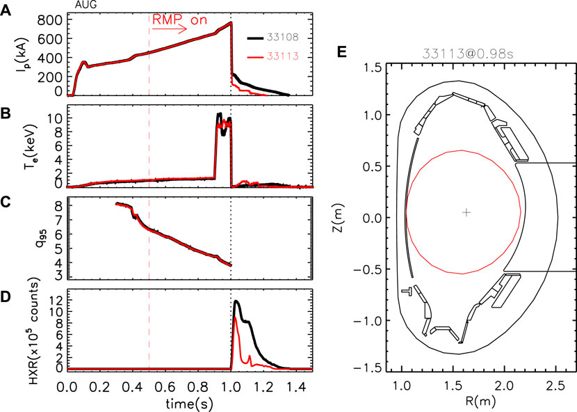
Figure 1. Evolution of (A) plasma current, (B) core electron temperature, (C) safety factor at the edge, and (D) HXR emission for two different shots: in black for a standard one (no mitigation methods used) and in red for a discharge where RMPs by the B-coils are applied from t = 0.5 s (vertical dashed line). The dashed vertical black line at 1 s corresponds to the time of disruption. (E) equilibrium reconstruction for the last closed surface of shot 33113 at 0.98 s.
Self-consistent simulations of ASDEX Upgrade RE dynamics using the Hesslow model [52, 53] have shown a good agreement between the experimentally measured runaway current and modeling, in contrast to the classical avalanche model, using which the final runaway current was overestimated by
ASDEX Upgrade is equipped with a set of 16 non-axisymmetric in-vessel coils [54] in the form of two toroidal rows of eight coils (termed B-coils) above and below the tokamak mid-plane on the outer side of the torus (low field side). They were powered by four independent power supplies that produce a radial field of 3 mT at the plasma boundary in front of an upper coil (br/BT ∼ 10–3). The B-coils can generate resonant magnetic perturbations with dominant toroidal mode numbers n = 1, 2, 4. The poloidal mode number spectrum m is defined by the poloidal dimension of the coils and their reciprocal distance; generally, there is no single corresponding m but a broad spectrum of modes and harmonics. The differential phase ΔΦ between the current harmonic flowing in the upper (Iupper) and lower (Ilower) set of coils can be modified in order to change the alignment of the perturbation field with respect to the equilibrium magnetic field lines. The differential phase ΔΦ is defined through the following relations: Iupper ∝ cos (nϕcoil) and Ilower ∝ cos (nϕcoil + ΔΦ), where ϕcoil is the toroidal angle location of the center of a B-coil [55].
In the experiments reported in this paper, ΔΦ steps of 45° are performed, and the perturbations generated are characterized by a dominant n = 1 toroidal mode number; the B-coils carry a maximum current of IB = 1 kA and are turned on 500 ms before the disruption, at t = 0.5 s. Indeed, at least approximately 0.3 s are required for the 3D fields to build up and reach the maximum value inside the plasma. Since RMPs are applied before the disruption event, the RE seed introduced by ECRH is expected to be partially de-confined by the perturbations, which might reduce the avalanche effect during the TQ and CQ phases.
An example of discharge with magnetic perturbations applied with ΔΦ = 90° is shown in Figure 1 (red). Figure 1A shows that both the initial runaway current and the beam duration in the post-disruption phase are almost halved with respect to the unmitigated RE discharge without external field application. Similarly, the HXR signal decreases by a factor of
The phenomenology observed above is present only for specific differential phases of the B-coils. A scan in ΔΦ was performed, and some examples of the final currents and HXR measurements during the RE beam phase are reported in Figure 2. No significant effect of the applied perturbation is visible for ΔΦ = 0°, 180°, and 270°. However, both the discharges reported in this plot with ΔΦ = 90° are characterized by a reduction in the RE current (∼− 40%) and HXR emission (∼− 60%). This behavior is even more pronounced for ΔΦ = 45°, where the runaway beam initial current is much lower than that in the other discharges (
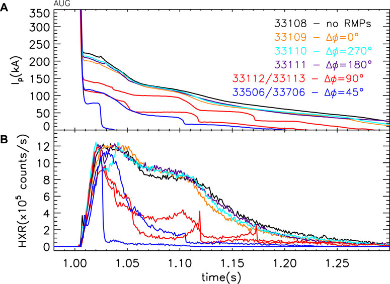
Figure 2. (A) Plasma current during the post-disruption phases for different values of ΔΦ and (B) corresponding HXR emission.
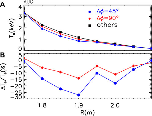
Figure 3. (A) Electron temperature profile by ECE averaged between 0.9 and 1 s and for different classes of discharges: no RMPs applied (black squares), Δϕ = 90° (red diamonds), and Δϕ = 45° (blue circles). (B) Percentage variation in Te with respect to the unperturbed shots.
A couple of discharges have been performed shifting the time of RMP application to 0.2 s before the disruption; in this case, the RE beam current was slightly below the current of a shot without RMP application. Similarly, two shots with RMPs applied at the disruption time also show no effect on the RE beam current and on its evolution and duration.
The poloidal spectrum of the applied 3D fields has been evaluated in vacuum approximation at the time t = 0.98s, just before the disruption event, for more differential phases of the B-coils. Two examples are shown in Figures 4A–B of Figure 4 as a function of the poloidal wave number m and of the normalized poloidal flux coordinate (ρpol) for ΔΦ = 45° and ΔΦ = 315°, respectively. They correspond to the two phasings with the minimum and maximum resonant components in vacuum approximation. Indeed, the safety factor profile is plotted with a white dotted line, and the resonant positions corresponding to q = 3 and q = 4 are marked with dots. The ΔΦ = 45° case shows that the maximum perturbed field occurs in the edge region and between the non-resonant components m = 5 and m = 6; the resonant position with q = 4 conversely lies in a region of low field
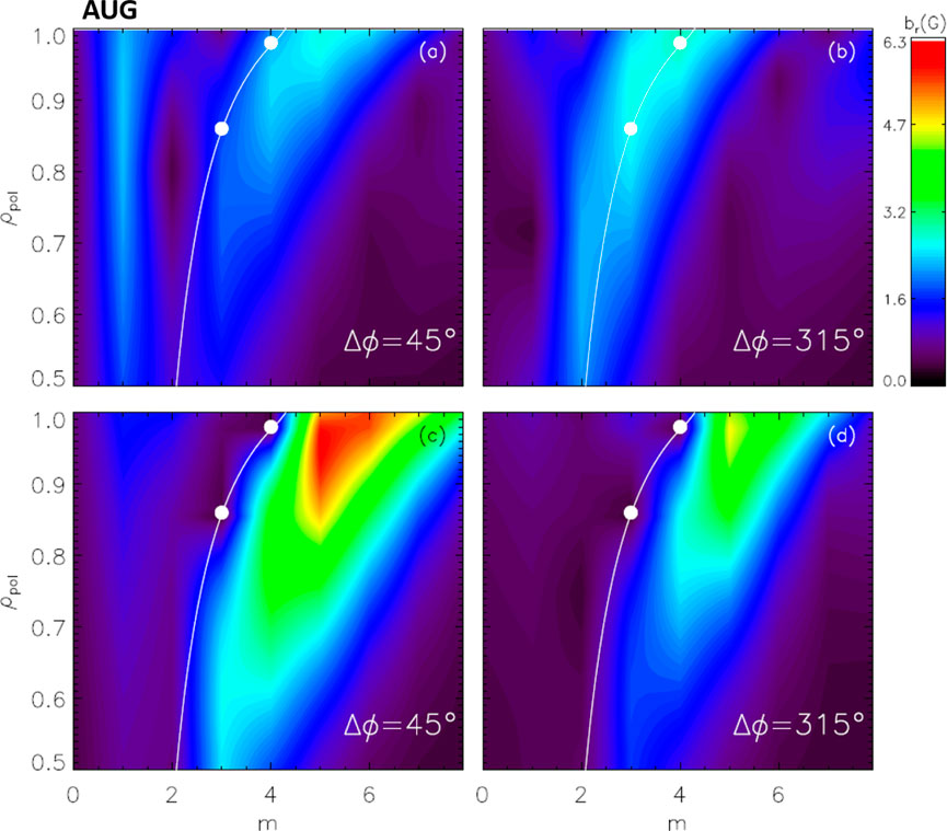
Figure 4. Contour of perturbed field function of the m component and normalized poloidal flux for two values of the B-coil differential phase with (A) 45° and (B) 315° in vacuum approximation while (C) 45° and (D) 315° including the plasma response. In all the plots, the white dots are the resonance positions q = 4, 5, and the thin white line is the safety factor profile.
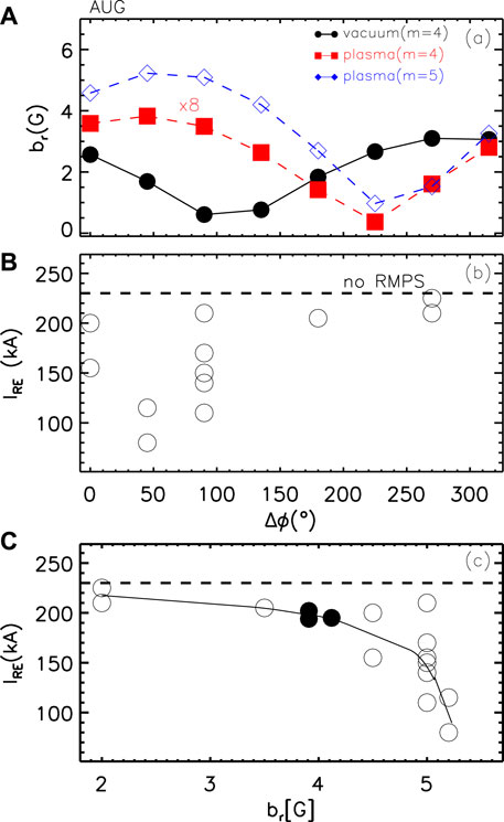
Figure 5. Dependence on Δϕ of the (A) perturbed field amplitude at the resonance q = 4 in vacuum approximation (black) and with plasma response (red, multiplied by a factor 8), and of the kink mode m = 5 in the edge region blue; (B) post-disruption RE current. (C) post-disruption RE current vs. perturbed field amplitude m = 5 evaluated by MARS-F; the full dots correspond to shots with Δϕ = 45° but IB ∼ 0.8 kA.
The code MARS-F [57, 58], which solves the single-fluid, linearly perturbed MHD equations in full toroidal geometry, has been used to calculate the poloidal spectrum, including the plasma response to RMPs. Figures 4C, D show the results obtained for ΔΦ = 45° and 315° relative to an equilibrium preceding the disruption (reference shot: 33113, t = 0.98 s); the corresponding kinetic quantities such as electron/ion temperature and density profiles are provided by the integrated data analysis (IDA) [59] of diagnostics as a result of a coherent combination of measurements based on the Bayesian probability theory. In these simulations, a toroidal rotation of ω/ωA = 5 ⋅ 10–3 is assumed (ωA is the Alfvén frequency for the considered plasmas). In both cases, the plasma response reduces the amplitude of resonant harmonics at the corresponding rational surfaces compared with the vacuum field; conversely, the kink relative to the components m = 5, 6 for ΔΦ = 45° is enhanced by more than a factor 3. The same analysis has been performed for more ΔΦ and toroidal rotation values.
The m = 4 resonant component at q = 4—computed including the plasma response—is shown in Figure 5A with red squares; its amplitude is reduced by a factor
The findings presented above do not depend on the toroidal rotation if ω/ωA is between 10–3 and 5 ⋅ 10–3. An estimate of the experimental toroidal flow can be inferred from the rotation frequency of the inner n = 1 mode when present and is of the order of
Figures 3, 4, 5 show how RMPs with maximum plasma response affect the thermal confinement (temperature profiles and TQ dynamics); therefore, a combination of effects might occur to determine a lower runaway current: on one hand, perturbations affect the RE seed already before the disruption (i.e., reduce the avalanche effect); on the other hand, the generated REs are lost in a shorter time because of enhanced transport. These findings are not in contradiction with previous ones observed in other devices; rather, they make us suppose that, in past experiments, the RMP poloidal spectrum harmonic component could not have been sufficiently high due to a wrong phasing or to the geometry of the coils. In addition, the simulations performed to interpret the data relied only on vacuum field approximation. The results reported here, combined with disruption predictive models [63–66] and in synergy with standard mitigation methods, might also be relevant for RE suppression in future fusion reactors.
The total perturbed field (vacuum + plasma response) of the resonant field components is relevant in the formation of magnetic islands (e.g., harmonics (4,1) and (3,1)) and, potentially, can be responsible for field line ergodization. However, the non-resonant part (kink amplification) that does not necessarily ergodize fields further contributes to RE suppression (by coupling to the resonant spectrum or direct orbit modification). In this sense, the combined results reported in Figures 4, 5 point to two mechanisms both occurring at the same favorable coil phasing, which could affect the primary generated runaway electrons, thus reducing the initial seed, or those produced in the avalanche process. Nevertheless, a deeper understanding of these issues would require a detailed analysis and/or an investigation with a two-fluid approach [67], considering also nonlinear effects in the plasma response to RMPs. When two-fluid terms are included in the response calculations, the ion and electron velocity are no longer the same; in particular, the electron velocity tends to be the relevant quantity controlling the field penetration in the core of the plasma at the mode-rational surface. Conversely, the excitation of edge modes is mainly correlated with ion velocity [68]. Another approach for the interpretation of these experimental results consists in the direct modeling of the RE trajectories [69] in the 3D fields generated by the B-coils corrected with the plasma response effects, as described in the following subsection.
The Hamiltonian guiding center code ORBIT upgraded to a relativistic version has been applied to investigate the impact of MPs on REs of different energies in the experiments performed at AUG. A qualitative approach is used in this paper for the simulations; indeed, the reconstruction of the plasma response during the dynamic disruption phase is more complex since the system changes from an Ohmic to a plasma dominated by electrons. Moreover, a complete distribution function should be considered to treat in detail the transport of electrons. Here, we consider them as test particles placed in different positions of the device to verify how they react to the applied 3D fields. Nevertheless, despite these limitations, as shown below, the simulations can well describe the different impacts of RMPs on the electron drift and losses when varying the plasma response, consistently with the observed phenomenology.
ORBIT simulations in AUG point out that despite the lack of macroscopic chaotic regions, the most efficient coil configuration enhances the test electron drift and the associated losses with a strength depending on the particle energy. Moreover, this mechanism is found to be important in the disruption phase, when the effect of the induced toroidal electric field is also included in the simulations.
The equilibrium given as input to the code corresponds to the time t = 0.98 s, just preceding the disruption event with q95 = 4.5. The radial eigenfunctions relative to the m components of the n = 1 perturbations from MARS-F are implemented in ORBIT, as described in [70]. The Poincaré maps reconstructed for the most and least efficient phasing (i.e., Δϕ = 45° and Δϕ = 180°) do not show a macroscopic stochasticization of the field but only larger magnetic islands for Δϕ = 45° (see [70] for the plots and more details on this issue). When considering the high-energy particle orbit phase space, the magnetic islands become more distorted and shift toward the outer region; in particular, in the case with Δϕ = 45°, the drift of the islands barely intercepts the last flux surface.
Numerical simulations have first involved the pre-disruption phase by performing several ORBIT runs following the trajectories of 2000 electrons varying their energy and the phasing of the applied RMPs. Such a number of particles is a compromise between the desired statistics and the duration of the ORBIT runs. Only small differences
The thermal quench phase in AUG is triggered by injecting Ar gas in the plasma and corresponds to the phase with the plasma temperature collapsing from its pre-disruption value to almost 0 (in approximately 1 ms); the following decay of the conductivity generates a huge toroidal electric field, which rapidly increases the electron energy. Then, during the following current quench phase, the number of high-energy electrons exponentially increases by the avalanche mechanism. Since RMPs are still applied during the TQ and CQ phases, they can further affect the runaway confinement. Simulations by ORBIT relative to these phases have been performed including the effect of the induced electric field and still keeping the same pre-disruption equilibrium. The latter assumption, in particular, is strictly correct only in the initial CQ phase; indeed, after few ms, q95 increases to
The run time corresponds to 0.8 ms, comparable with the initial CQ-phase duration. The inclusion of the electric field allows for the passing electrons to increase their energy and, thus, to enhance their orbit drift so that they can more easily be lost to the wall. At the end of a run, the still confined particles are characterized by the energy distributions reported in Figure 6A relative to the two phasing Δϕ = 45° (red solid line) and 180° (black thinner line). The peak centered at 4 MeV, the initial energy of the electrons in these runs, is mainly due to trapped particles that do not acquire kinetic energy during their banana orbits. On the other hand, the distribution close to E ∼ 7 MeV is almost composed of passing electrons. The plots on this panel also highlight the relevance of the plasma response when Δϕ = 45°: the total number of confined electrons is lower than in the 180° phasing. Concerning the electrons escaping from the plasma, panel (b) shows the relative pitch and loss times. The most efficient phasing increases the losses at all times, especially between 10–3 and 0.1 ms with pitch λ ∼ 0–0.6 (trapped + barely passing particles) and at smaller times, below few μs for λ ∼ 0.8–1 (fully passing electrons).
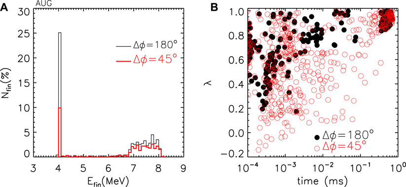
Figure 6. (A) Final energy distribution for confined electrons in simulations relative to the disruption phase and with E = 4 MeV; (B) lost electrons: final pitch and loss time for the two phasings Δϕ = 45°, 180° and E = 4 MeV.
Two examples of particle motion are shown in Figure 7 relative to electrons with the same initial energy and pitch but with different RMP phasings applied. Panel (a) shows the normalized poloidal flux time evolution (i.e., ∼ the normalized radial position) of a 500-keV barely passing electron under the action of perturbations with Δϕ = 45° (red) and 180° (black). In the latter case, the electron oscillates around the same position close to 0.9 and is never lost. In contrast, the application of the other phasing modifies the trajectory of the electron after a couple of μs: it becomes trapped and is lost after few bounces in approximately
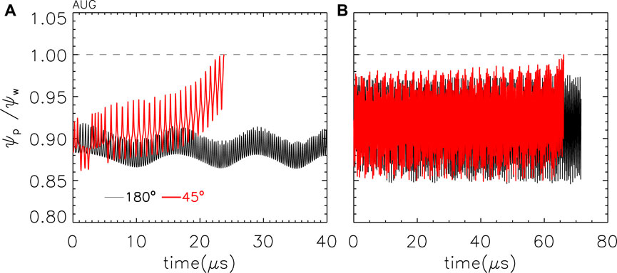
Figure 7. (A) Motion of two electrons with the same initial conditions and energy of 500 keV but subjected to different phasings of RMPs; (B) similar quantities but for two electrons with an initial energy of 4 MeV.
Figure 8A shows the ratio of the not-lost electrons Nfin between the case with Δϕ = 45° and Δϕ = 180° as a function of the initial energy implemented in the simulations. While for E < 1 MeV the number of confined electrons is similar with the two phasings Nfin,45/Nfin,180 ∼ 1, at higher energies (8–10 MeV), the fraction of surviving electrons with the most efficient phasing rapidly decreases to
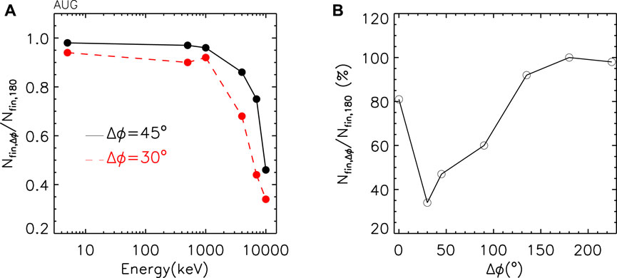
Figure 8. (A) Ratio of not-lost electrons with the two phasings applied with respect to 180° as a function of electron energy; (B) scan in phasing at a fixed energy of E = 10MeV.
For the energy E = 10 MeV, a complete phasing scan has been performed. The results are shown in Figure 8B with the ratio Nfin,45/Nfin,180 as a function of Δϕ. The fraction of surviving electrons has a clear minimum at Δϕ = 30° (35%) and is also characterized by a lower value with respect to the most performing experimental phasing (+45%).
As stated above, the approach used in these simulations is qualitative; indeed, the plasma response during the dynamic disruption phase is much more complicated, and the system also changes from an ohmic to an electron plasma. Nevertheless, the modeling described here can explain and reproduce the different effect of perturbations on the electron drifts and losses consistently with the experimental data phenomenology. In particular, the main mechanism leading to RE losses seems to be related with the kink and the associated drift effects; indeed, no clear ergodization is observed. In a predictive purpose, the code identifies the presence of a maximum in terms of electron losses for the coil configuration corresponding to Δϕ = 30°. Such a value would allow us to enhance the RE mitigation and, thus, to reduce the RE beam current.
The tokamak COMPASS (major radius R0 = 0.56 m and minor radius a = 0.23 m) features ITER-like plasma shapes with a toroidal field BT = 0.9−1.5 T and a plasma current Ip < 350 kA [46]. Here, limiter circular plasmas are considered with BT = 1.15 T oriented in the same direction as Ip (clockwise from the top view). The upper/lower MP coil systems in COMPASS allow the application of perturbations with toroidal mode numbers n = 1 and n = 2 both before and after a disruption is induced [71, 72]. The current (IMP) flowing in the MP coils can be increased up to 4 kA corresponding to a radial field normalized to the main toroidal field of bMP/BT ∼ 10–2. The sign of the current in the upper and lower set of coils can be varied in order to obtain different configurations (or differential phasing Δϕ, like in AUG) for the poloidal spectrum of the applied perturbations. With n = 1, the number of phasings available is 4 (Δϕ = 0°, 90°, 180°, and 270°); if n = 2, only two configurations are possible: even (Δϕ = 0°) and odd (Δϕ = ±90°) orientation.
Figure 9 shows an example of a standard COMPASS discharge (black line) where a disruption is induced by argon puffing (1.2 bar,
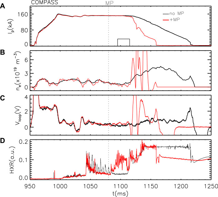
Figure 9. Example of disruptive discharges in COMPASS without (black, #15774) and with (red, #15775) MPs applied; from the top: (A) plasma current, (B) electron density (oscillations in the red trace after disruption are caused by fast variations in the radial RE beam position and other signals), (C) loop voltage, and (D) HXR radiation. The MP pulse starts at the time corresponding to the vertical dotted line, and the Ar injection is represented by a rectangle in the top panel.
These experiments have been repeated by varying the phasing of the n = 1 mode and the current in the MP coils. The magnitudes of pre-MGI-applied MP were limited in the experiment for avoiding the locking of magnetic island rotation that disrupts the discharge without RE generation (this occurs for MPs with Δϕ = 0°, 90°, IMP > 1 kA or with Δϕ = 180°, IMP > 3 kA). The results are given in Figure 10A with the RE beam duration ΔtRE—measured from the end of Ar puffing (1,115 ms) to the time when the RE current decreases to below 30 kA—as a function of IMP; each color/symbol corresponds to a different phasing. Up to IMP = 1.5 kA, a significant effect of the MPs on the RE beam is not visible: for all Δϕ values, the duration is similar to the one typical of unperturbed reference discharges (empty circles).
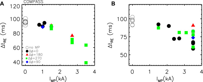
Figure 10. Runaway beam duration (ΔtRE) as a function of MP amplitude (IMP) for different phasing values (colors/symbols). (A) MPs have been applied before the disruption; (B) after. The legend in (A) also applies to (B).
In contrast, for IMP > 2 kA and Δϕ = 270°, the duration decreases in the range 40–60 ms. Similar experiments have been performed with perturbations applied after the disruption (at tMP = 1135 ms), when the RE beam is fully generated; a summary of the main findings is shown in Figure 10B. An almost linear trend can be observed for the phasing Δϕ = 0°. Furthermore, Δϕ = 270° (green squares) can slightly reduce the RE beam duration but with a lower efficiency than Δϕ = 0°, except for in a single case at 3.5 kA where ΔtRE decreases to
Further discharges have been performed using MP with n = 2 instead of n = 1. The results are shown in Figure 11 both for perturbations applied before and after the runaway beam generation. As clear from circle symbols, pre-existing MPs with n = 2 in most the cases reduce the duration of the RE beam (from
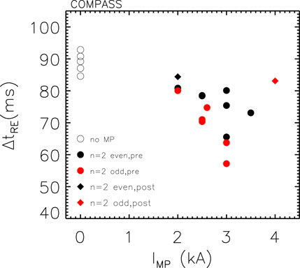
Figure 11. Runaway beam duration (ΔtRE) as a function of amplitude (IMP) of odd- and even-parity n =2 MP, applied before or after disruption.
A fraction of discharges has been performed also using Ne instead of Ar for MGI and is characterized by a larger variation in the RE beam duration (80–140 ms). The application of n = 1, 2 MPs—both before and/or after the disruption—in this case also has a clear impact on the runaways but less systematic with respect to Ar; more experiments to reinforce the statistics are required.
The results reported in the previous sections have been interpreted including the plasma response to the applied MPs by using the code MARS-F, similar to that in the first section for ASDEX Upgrade. The simulations have been performed considering the equilibrium quantities (main field, plasma current, density, and temperature) relative to a time (1080 ms) preceding the disruption and the RMP application. Indeed, in the following phase, during the Ar/Ne puffing or the RE beam decay, most of the usual parameters are not well-defined since the plasma is degenerate, being composed only of electrons. As central temperature, a value of Te (0) = 226 eV has been chosen, and for the electron density, ne (0) = 0.45 ⋅ 1019m−3, both obtained from Thomson scattering measurements. The ion temperature is assumed to be the same as the electron temperature. The toroidal flow velocity in COMPASS corresponds to a rotation frequency of
The computed components of the perturbation field at the resonance positions q = m/n = 2/1 and q = 3/1 are shown in Figure 12 as a function of Δϕ both in vacuum approximation and considering the plasma response to MPs. They present a maximum for the m = 2 (3) components at Δϕ = 230° (270°) in vacuum, which is shifted to Δϕ = 330° (350°) if the plasma response is included; thus, these numerical simulations allow us to interpret the experimental data shown in Figure 10 as a result of the resonance between MPs and pre-disruption plasma equilibrium: indeed—for the same IMP—the strongest effect is observed at Δϕ = 0°. On the other hand, it is not possible to make a direct comparison between simulations and experiments with pre-existing MPs (Figure 10A) since a complete scan of the MP current was available only for one phasing (270°) because of lock modes or disruptions in the rest of the Δϕ values.
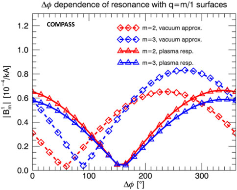
Figure 12. Perturbed field at resonant positions q = 2 (red) and q = 3 (blue) in vacuum (diamonds) and with plasma response (triangles) as function of the phasing for n = 1 MP.
A more direct comparison between the results from MARS-F simulations and the experimental data is shown in Figure 13. The panel on the left shows the durations of the RE beam—when RMPs with 3.5 kA of coil current amplitude are applied after the disruption—vs. the radial field at resonant positions q = 2 (red) and q = 3 (blue); each point corresponds to the average of the RE beam duration Δt relative to the same phasing (i.e., the data given in Figure 10B at the maximum IMP). Such a plot does not present any trend but only a cloud of points. In contrast, if the plasma response is included, the right-hand side panel is obtained, where a clear decrease in the beam duration as a function of the radial field computed by MARS-F is visible. Such a plot further highlights how the field component important at the resonance q = 2 and q = 3 is not the one computed in vacuum approximation but the one accounting for plasma response as well.
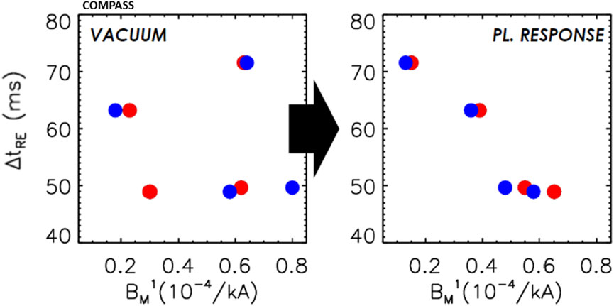
Figure 13. RE beam duration as a function of n = 1 radial field at q = 2 (red) and q = 3 (blue) in vacuum approximation (left) and including plasma response (right).
Similar simulations by MARS-F for the n = 2 perturbations confirm the presence of a stronger plasma response in the odd-parity configuration as occurs in experimental discharges when MP application precedes the disruption. In experiments, we observed that Δϕ = 90° was better at mitigating REs than 0°. According to modeling results in the Δϕ scan plot (Figure 14), the 6/2 resonance is indeed approximately 50% stronger at 90° than it is at 0°; however, the 4/2 resonance is basically the same there. This could imply that the edge resonance (q = 3 is very close to the last surface) is of more importance to RE mitigation than the resonance deeper in plasma on the q = 2 surface. Furthermore, we observed that vacuum approximation would be yet completely wrong in the prediction of RE mitigation, as it clearly shows worse resonance at 90° than at 0° in contrast to the experiment. Another interesting case to compare would be 45°–135° since they correspond to the maximum and minimum of resonant coupling when the plasma response is taken into account, as can be seen from the Δϕ plot in Figure 14. Unfortunately, COMPASS does not have such a freedom in Δϕ for n = 2 RMPs.
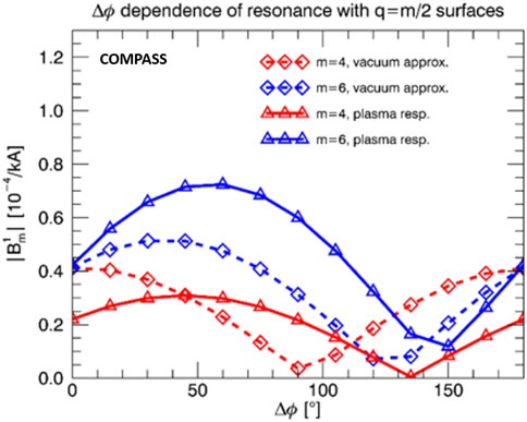
Figure 14. Perturbed field at resonant positions q = 2 (red) and q = 3 (blue) in vacuum (diamonds) and with plasma response (triangles) as a function of the phasing for n =2 RMPs.
Using a similar approach to the one adopted for numerical simulations in ASDEX Upgrade in the previous section, the experimental findings on RE mitigation in COMPASS have also been analyzed by means of the ORBIT code. To this end, a pre-disruption equilibrium has been considered with q = 3 at the edge. n = 1 perturbations provided by MARS-F have been implemented in the code with four phasing Δϕ (i.e. 0°, 90°, 180°, and 270°); for each case, the variation in the amplitude allows us to explore more values of current applied by the RMP coils IMP. As initial conditions, a random distribution in the position (i.e., in the radial coordinate and poloidal/toroidal angle) and pitch (in the range [−1, 1]) of 2000 electrons has been assumed with an energy of 2 MeV. The run duration corresponds to a time of 0.1 ms; at the end, the number of electrons lost from the plasma and their parameters are recorded.
Figure 15 shows with a dotted black line the cumulative distribution of losses in a run with no perturbations applied. Electrons are lost at the very beginning of the run, within 0.1μs and amount to the 17% of initial population; then, the total losses do not increase anymore till the end. A different scenario occurs when the modes are implemented with Δϕ = 270° and turned on with a value corresponding to a coil current of 3.5 kA, the maximum one tested in the experiment. As clear from the solid red line, a fast growth of the cumulative distribution is still visible in the first μs (basically the same observed in the equilibrium case), but then, electrons continue to be lost up to 21% of their initial number. Such loss mechanisms would further keep going when considering longer runs, in contrast to the equilibrium scenario where a saturation effect is observed.
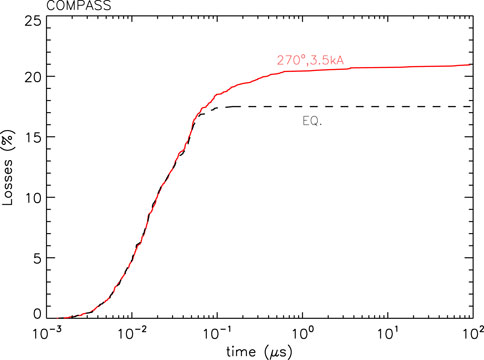
Figure 15. Cumulative distribution losses for COMPASS numerical simulations by ORBIT in the unperturbed case (dotted black line) and in the one with perturbations implemented (solid red line).
For a qualitative comparison with the experimental data, in the following equation (Eq. 1), the loss enhancement (loss enh.) has been considered, i.e.,
where Nloss(Δϕ) is the loss amount when perturbation with phasing Δϕ is applied and Nloss(EQ.) is the same quantity but in runs with only the unperturbed equilibrium. The results are shown in Figure 16: in panel (a), the loss enhancement has been plotted as a function of the coil current for different phasing, while in (b), the dependence vs. Δϕ is highlighted. As in the experiment, the enhancement of lost electrons increases with the current, i.e., with the amplitude of the perturbations and with a clear different behavior of the two cases at Δϕ = 270°, 0°—where the increase is of the
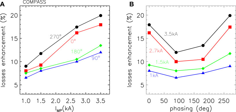
Figure 16. (A) Loss enhancement with respect to the equilibrium case vs. the current amplitude of the RMP coils for different phasings of the perturbations implemented in ORBIT; (B) loss enhancement as a function of the phasings for different IMP values.
These findings do not depend significantly on the initial energy assumed for the runaway electrons as verified in similar ORBIT runs performed with E = 500keV, 1MeV, 5MeV, and 10 MeV. Qualitatively, the same trends reported above are reproduced but with an absolute number of lost electrons increasing with the energy both for simulations with the equilibrium only and with the perturbations implemented, a behavior probably just due to the larger drift experienced by the runaways rather than to RMPs. Such a topic requires to be further investigated; different conclusions can also be found in literature, as those described in [73, 74], where runaway electrons appear to be less sensitive to perturbations at higher energies.
In conclusion, similar experimental results have been obtained in ASDEX Upgrade and Compass on RE mitigation by MP application, even in the presence of different pre-disruption plasma currents, geometry, and magnetic field strengths. The reported results can be explained only if the plasma response to the applied perturbation is included in the simulations, as shown by the reconstructions performed by means of the MARS code. Numerical modeling of test particle transport by the ORBIT code in the presence of the MHD modes provided by MARS can qualitatively reproduce the observed phenomenology in both the devices.
Thanks to its advanced system for the control of magnetohydrodynamic modes based on 192 independently fed saddle coils [75], RFX-mod is particularly suitable to explore the RE de-confinement in response to applied magnetic perturbations with different modal numbers and amplitude both during the flat-top phase, on primary generated runaways, and on the post-disruption plateau. The RFX-mod experiment, with a major and minor radius of R0 = 2 m and a = 0.459 m, respectively, not only works as a reversed-field pinch device but also as a low-current ohmic tokamak. The active control system allows us to achieve regimes with q(a) down to
The high-energy electron dynamics in the RFX-mod is investigated thanks to the soft X-ray (SXR) tomography and using two scintillators based on an NaI(Tl) crystal (placed at the toroidal angles ϕ = 157.5° and ϕ = 262.5° on the mid-plane) coupled to a photomultiplier for the detection of HXRs generated when the electrons escape the plasma and impact the first wall. A statistical study, carried out over about 150 tokamak deuterium discharges, shows that most of the RE events occur at densities lower than 4 ⋅ 1018m−3 and with a toroidal electric field in the range 0.03–0.1 V m−1 (the theoretical critical field Ec is
As found in the experiments described in the previous sections, radial magnetic fields might prevent the electrons from reaching high-energy levels before being lost. In this case, the presence of MPs generates partially chaotic regions. Due to the fast radial diffusion within these domains, electrons can leave the plasma in a shorter time and with lower energy with respect to the unperturbed configuration. To investigate this issue, MPs were applied during the (feedback-stabilized) flat-top phase of low-density RFX-mod tokamak discharges; an example is shown in Figure 17, where a 10-Hz rotating (2,1) mode (panels (c)-(d)) is applied to a plasma with q(a) < 2 (current in panel (a)). The amplitude of the MP increases linearly to a value of 0.3 mT (0.05% of the edge toroidal field BT(a) = 0.55 T) in the time interval 0.3–0.55s and then decreases to 0 at t = 0.8 s. The scintillator HXR signal (IHXR) is reported in panel (b): two different modulations are clearly visible, the first (approximately 10 Hz) characterized by five relative maxima, which are correlated to the mode phase (d), the second, slower, scaling with the perturbation amplitude. IHXR, proportional to the energy of RE reaching the diagnostic, decreases from
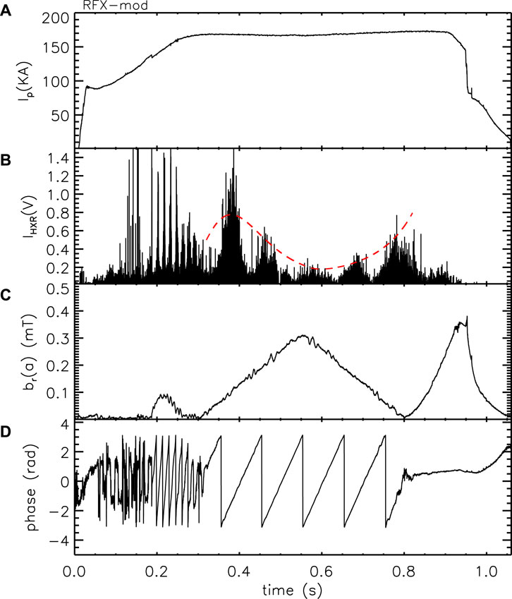
Figure 17. (A) Plasma current, (B) HXR signal, (C) radial field component for the (2,1) mode, and (D) phase for the shot #33640. In red (dotted line), in (B), the slower modulation of the HXR signal is highlighted.
The same dependence of IHXR on the perturbation amplitude has been observed in many discharges with applied perturbations. Figure 18 shows the HXR signal normalized to its maximum value Imax (the latter might vary from shot to shot) as a function of the normalized perturbation amplitude br(a)/BT(a). The plot suggests that the RE energy decreases with the amplitude of the perturbation in most cases, with a reduction in
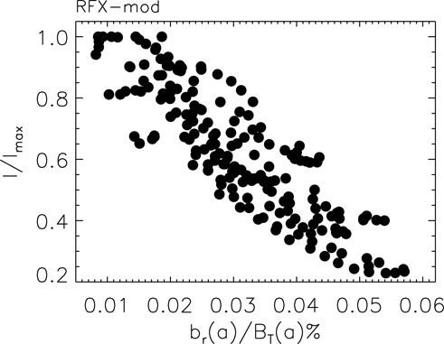
Figure 18. Normalized HXR amplitude as a function of br(a) for several shots.
There are also cases of REs generated during discharges with q(a) > 2 where spontaneous (2,1) tearing modes (TMs) develop without inducing a disruption. By using a statistical approach over many shots with similar features in terms of density, current, and magnetic field, it is found that the maximum HXR signal decreases with the amplitude of the mode and is almost 0 as br(a)/BT(a) > 0.06%. Such a behavior is still a consequence of the stochasticity induced by the (2,1) mode, which prevents runaway electrons from reaching high energies before being lost to the wall. Such an effect is still greater than that in the q(a) < 2 scenarios since the (2,1) TM is resonant.
These experiments, as those presented in the previous sections, have been interpreted by means of the ORBIT code in its relativistic version. The simulations consider two different circular equilibria with q(a) < 2 and q(a) > 2. The radial profiles for the eigenfuction of the (2,1) modes have been reconstructed by a Newcomb approach [28], including the plasma response, and several amplitudes are taken into account. Figure 19A shows the fast-electron phase space for 500 keV runaway electrons in the case with q(a) > 2 and an amplitude of the perturbation of br(a)/BT(a) ∼ 0.1%. Indeed, because of the high RE energy, the magnetic topology might differ from the particle orbit space, and the latter is the one relevant to determine the RE confinement properties and relative losses. In these simulations also, a (1,1) mode is included with a fixed amplitude; this periodicity is not resonant, but its coupling with the (2,1) perturbation generates resonant secondary modes, which lead to magnetic island formation (for instance, the (3,2) or the (4,3) from the further coupling of (3,2) + (1,1)). The partial overlapping between these islands might create regions of the plasma with partial stochasticity, in particular at the edge of the poloidal section, as shown in Figure 19A, which might be responsible for runaway electron losses. Test particle transport simulations have been performed in order to determine the RE losses in the presence of the (2,1) perturbation with different mode amplitudes of the toroidal electric field (ET = 0.05 V m−1), as well as of slowing down and pitch angle scattering collisions (assuming ne = 2 ⋅ 1018 m−3, Te = 600 eV). A total of 500 electrons with an initial energy of E = 100 keV and random pitch angles are considered with a spatial distribution linearly decreasing from the center to the edge of the plasma. The simulations last for a time corresponding to
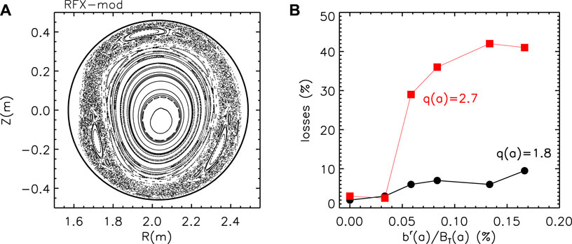
Figure 19. (A) 500-keV electron orbit space at br/BT(a) = 0.1% and q(a) > 2 (poloidal cross-section); (B) fraction of lost electrons as a function of the (2,1) mode amplitude in the case with q(a) < 2 (black/circles) and q(a) > 2 (red/squares).
During the RFX-mod tokamak campaign, few experiments have been dedicated to the mitigation of REs by applied perturbations in post-disruption phases in discharges with flattop Ip = 90 kA. To this end, a disruption is induced by increasing the radial field of the (2,1) mode up to 0.5 mT; then, the current is kept constant for about half a second at
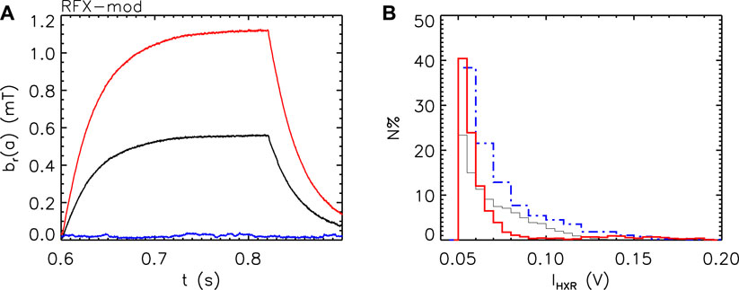
Figure 20. (A) Radial field (2,1) mode amplitude applied during the post-disruption phases; (B) the corresponding histogram of the HXR signal amplitude distribution for IHXR > 0.05 V.
The effect of the MP on the REs can be observed from the histogram in panel (b), which shows the amplitude of the HXR signal for the discharges with the three different perturbations. Such an analysis has been limited to those events with IHXR > 0.05 V and clearly shows a reduction as the MP increases. It is worth noting that the HXR signal corresponding to the highest mode amplitude (red) is also characterized by a few RE events at greater energy (i.e., HXR signal); these are probably due to the enhancement of the toroidal electric field occurring in that particular shot between 0.7 − −0.8 s.
These results are only preliminary, and their statistics should also be increased taking into account the effect of other resonant and non-resonant modes, rotating with different toroidal and poloidal numbers. New experiments on these items are planned to be performed in the modified RFX-mod device [78, 79], which should become operative in 2024.
In this paper, we summarized the recent experimental results on RE mitigation by applied magnetic perturbations in ASDEX Upgrade, COMPASS, and RFX-mod in its tokamak version. The execution of the experiments in these three devices allows us to cover a wide range of parameters in terms of toroidal field (from
The results presented in this paper suggest that in previous experiments, which were not successful in RE mitigation by RMP application, the poloidal spectrum of the perturbations was probably not the most efficient one due to an unfavorable phasing or to the peculiar geometry and configuration of the coils. Even if other techniques like shattered pellet injection, together with benign termination, must be used to completely suppress the RE generation and are those expected to be implemented in larger devices like ITER or DEMO, the method of MP application can still make a complementary contribution. Indeed, it could be used to prevent or at least minimize the RE beam formation if applied prior to the current quench in the context of a series of actions triggered by real-time models that predict the occurring of a disruption. The reduced RE beam current in this way could be easily completely dissipated by the other standard methods, hence avoiding the damages to the plasma-facing components.
MG: conceptualization, data curation, formal analysis, investigation, software, writing–original draft, and writing–review and editing. MV: conceptualization, investigation, and writing–review and editing. LM: conceptualization, data curation, investigation, methodology, and writing–review and editing. GPP: conceptualization, data curation, formal analysis, investigation, methodology, and writing–review and editing. GPU: data curation, formal analysis, investigation, methodology, and writing–review and editing. ET: data curation, formal analysis, investigation, methodology, validation, and writing–review and editing. TM: methodology, software, validation, and writing–review and editing. OF: data curation, investigation, methodology, and writing–review and editing. JC: data curation, investigation, and writing–review and editing. YL: formal analysis, software, and writing–review and editing. LL: formal analysis, software, and writing–review and editing.
The author(s) declare that financial support was received for the research, authorship, and/or publication of this article. This work has been carried out within the framework of the EUROfusion Consortium, funded by the European Union via the Euratom Research and Training Programme (Grant Agreement No. 101052200-EUROfusion).
YL was employed by General Atomics.
The remaining authors declare that the research was conducted in the absence of any commercial or financial relationships that could be construed as a potential conflict of interest.
All claims expressed in this article are solely those of the authors and do not necessarily represent those of their affiliated organizations, or those of the publisher, the editors, and the reviewers. Any product that may be evaluated in this article, or claim that may be made by its manufacturer, is not guaranteed or endorsed by the publisher.
The views and opinions expressed are, however, those of the author(s) only and do not necessarily reflect those of the European Union or the European Commission. Neither the European Union nor the European Commission can be held responsible for them.
1. Kulsrud RM, Sun YC, Winsor NK, Fallon HA. Runaway electrons in a plasma. Phys Rev Lett (1973) 31:690. doi:10.1103/PhysRevLett.31.690
2. Dreicer H. Electron and ion runaway in a fully ionized gas. II. Phys.Rev (1960) 117:329. doi:10.1103/PhysRev.117.329
3. Carlson BE, Lehtinen NG, Inan US. Runaway relativistic electron avalanche seeding in the Earth’s atmosphere. J Geophys Res (2008) 113:A10307. doi:10.1029/2008JA013210
4. Gurevich AV, Valdivia JA, Milikh GM, Papadopoulos K. Runaway electrons in the atmosphere in the presence of a magnetic field. Radio Sci (1996) 31:1541–54. doi:10.1029/96rs02441
5. Lehtine NG. Trapped energetic electron curtains produced by thunderstorm driven relativistic runaway electrons. Geophys Res Lett (2000) 27:1095. doi:10.1029/1999GL010765
6. Stepan J, Kašparová J, Karlický M, Heinzel P. Hydrogen Balmer line formation in solar flares affectedby return currents. Astron Astrophysics (2007) 472:L55–8. doi:10.1051/0004-6361:20078170
7. Moghaddam-Taaheri E, Goertz CK. Acceleration of runaway electrons in solar flares. Astrophysical J (1990) 352:361. doi:10.1086/168543
8. Kaastra JS. Stability of an astrophysical plasma near the onset of electron runaway. J Plasma Phys (1983) 29:287–98. doi:10.1017/s0022377800000763
9. Houghton MJ. Electron runaway in turbulent astrophysical plasmas. Planet Space Sci (1975) 23:409–18. doi:10.1016/0032-0633(75)90115-4
11. Nucl. Fusion. The ITER physics basis. Nucl Fusion (2007) 47:S1–S413. doi:10.1088/0029-5515/47/6/S01
12. Hender TC, Wesley JC, Bialek J, Bondeson A, Boozer AH, Buttery AJ, et al. Chapter 3: MHD stability, operational limits and disruptions. Nucl Fusion (2007) 47:S128–202. doi:10.1088/0029-5515/47/6/S031
13. Hollmann EM, Parks PB, Commaux N, Eidietis NW, Moyer RA, Shiraki D, et al. Measurement of runaway electron energy distribution function during high-Z gas injection into runaway electron plateaus in DIII-D. Phys. Plasmas (2015) 22(5):056108. doi:10.1063/1.4921149
14. Lehnen M, Aleynikova K, Aleynikov P, Campbell D, Drewelow P, Eidietis N, et al. Disruptions in ITER and strategies for their control and mitigation. JNM (2015) 463:39–48. doi:10.1016/j.jnucmat.2014.10.075
15. Gill RD, Alper B, Edwards A, Ingesson L, Johnson M, Ward D. Direct observations of runaway electrons during disruptions in the JET tokamak. Nucl Fusion (2000) 40:163–74. doi:10.1088/0029-5515/40/2/302
16. Wesson JA, Gill R, Hugon M, Schüller F, Snipes J, Ward D, et al. Disruptions in JET. Nucl Fusion (1989) 29:641–66. doi:10.1088/0029-5515/29/4/009
17. Connor JW, Hastie RJ. Relativistic limitations on runaway electrons. Nucl Fusion (1975) 15:415–24. doi:10.1088/0029-5515/15/3/007
18. Granetz RS, Espoto B, Kim JH, Koslowski R, Lehnen M, Rhee T, et al. An ITPA joint experiment to study runaway electron generation and suppression. Phys Plasmas (2014) 21:072506. doi:10.1063/1.4886802
19. Boozer AH. Runaway electrons and ITER. Nucl Fusion (2017) 57:056018. doi:10.1088/1741-4326/aa6355
20. Hender TC, Wesey JC, Bialek J, Bondeson A, Boozer A, Buttery RJ, et al. The ITPA HD, disruption and magnetic control topical group. Nucl Fusion (2007) 47:S128. doi:10.1088/0029-5515/47/6/S03
21. Rosenbluth MN, Putvinski SV. Theory for avalanche of runaway electrons in tokamaks. Nucl.Fusion (1997) 37:1355. doi:10.1088/0029-5515/37/10/i03
22. Aymar R, Barabaschi P, Shimomura Y. The ITER design. Plasma Phys Control Fusion (2002) 44:519–65. doi:10.1088/0741-3335/44/5/304
23. Bakhtiari M, Kawano Y, Tamai H, Miura Y, Yoshino R, Nishida Y. Fast plasma shutdown scenarios in the JT-60U tokamak using intense mixed gas puffing. Nucl Fusion (2002) 42:1197–204. doi:10.1088/0029-5515/42/10/304
24. Bozhenkov SA, Lehnen M, Finken KH, Jakubowski MW, Wolf RC, Jaspers R, et al. Generation and suppression of runaway electrons in disruption mitigation experiments in TEXTOR. Plasma Phys Control Fusion (2008) 50:105007. doi:10.1088/0741-3335/50/10/105007
25. Reux C, Bucalossi J, Saint-Laurent F, Gil C, Moreau P, Maget P. Experimental study of disruption mitigation using massive injection of noble gases on Tore Supra. Nucl Fusion (2010) 50:095006. doi:10.1088/0029-5515/50/9/095006
26. Chen ZY, Yan W, Tong RH, Zhang XL. Dissipation of runaway current bymassive gas injection on J-TEXT. Plasma Phys Control Fusion (2019) 2:025002. doi:10.1088/1361-6587/ab52c8
27. Pautasso G, Fredrickson ED. Compressional Alfvén eigenmodes in rotating spherical tokamak plasmas. Plasma Phys Control Fusion (2016) 59, 035007. doi:10.1088/1361-6587/aa58fd
28. Taylor PL, Kellman AG, Evans TE, Gray DS, Humphery DA, Hyatt AW, et al. Disruption mitigation studies in DIII-D. Phys Plasmas (1999) 6:1872. doi:10.1063/1.873445
29. Commaux N, Baylor L, Combs S, Eidietis N, Evans T, Foust C, et al. Novel rapid shutdown strategies for runaway electron suppression in DIII-D. Nucl F.usion (2011) 51:103001. doi:10.1088/0029-5515/51/10/103001
30. Helander P, Eriksson LG, Andersson F. Suppression of runaway electron avalanches by radial diffusion. Phys. Plasmas (2000) 7:4106–11. doi:10.1063/1.1289892
31. Harvey RW, Chan VS, Chiu SC, Evans TE, Rosenbluth MN, Whyte DG. Runaway electron production in DIII-D killer pellet experiments, calculated with the CQL3D/KPRAD model. Phys Plasmas (2000) 7:4590–9. doi:10.1063/1.1312816
32. Yoshino R, Tokuda S. Runaway electrons in magnetic turbulence and runaway current termination in tokamak discharges Nucl. Fusion. (2000) 40:1293–309. doi:10.1088/0029-5515/40/7/302
33. Lehnen M, Bozhenkov SA, Abdullaev SS, Jakubowski MW. Suppression of runaway electrons by resonant magnetic perturbations in TEXTOR disruptions. Phys Rev Lett (2008) 100:255003. doi:10.1103/physrevlett.100.255003
34. Gobbin M, Valisa M, White R, Cester D, Marrelli L, Nocente M, et al. Runaway electron mitigation by applied magnetic perturbations in RFX-mod tokamak plasmas. Nucl Fusion (2017) 57:016014. doi:10.1088/0029-5515/57/1/016014
35. Hollmann EM, Commaux N, Eidietis NW, Evans TE, Humphreys DA, James AN, et al. Experiments in DIII-D toward achieving rapid shutdown with runaway electron suppression. Phys Plasmas (2010) 17:056117. doi:10.1063/1.3309426
36. Wongrach K, Finken K, Abdullaev S, Willi O, Zeng L, Xu Y. Runaway electron studies in TEXTOR. Nucl Fusion (2015) 55:053008. doi:10.1088/0029-5515/55/5/053008
37. Papp G, Drevlak M, Pokol G, Fülöp T. Energetic electron transport in the presence of magnetic perturbations in magnetically confined plasmas. J Plasma Phys (2015) 81:47581050. doi:10.1017/s0022377815000537
38. Papp G, Drevlak M, Fülöp T, Pokol G. The effect of resonant magnetic perturbations on runaway electron. Plasma Phys Controlled Fusion (2012) 54. doi:10.1088/0741-3335/54/12/125008
39. Aleynikova K, Huijsmans GTA, Aleynikov P. Linear MHD stability analysis of post-disruption plasmas in ITER. P Plasma Phys Rep (2016) 42:486–94. doi:10.1134/s1063780x16050019
40. Evans T, Moyer RA, Thomas PR, Watkins JG, Osborne TH, Boedo JA, et al. Suppression of large edge-localized modes in high-confinement DIII-D plasmas with a stochastic magnetic boundary. Phys Rev Lett (2004) 92:235003. doi:10.1103/physrevlett.92.235003
41. Lehnen M, Arnoux G, Brezinsek S, Flanagan J, Gerasimov S, Hartmann N, et al. Impact and mitigation of disruptions with the ITER-like wall in JET. Nucl Fusion (2013) 53:093007. doi:10.1088/0029-5515/53/9/093007
42. Izzo VA, Pusztai I, Särkimäki K, Sundström A, Garnier D, Weisberg D, et al. Runaway electron deconfinement in SPARC and DIII-D by a passive 3D coil. Nucl Fusion (2022) 62:096029. doi:10.1088/1741-4326/ac83d8
43. Tinguely RA, Izzo V, Garnier D, Sundström A, Särkimäki K, Embréus O, et al. Modeling the complete prevention of disruption-generated runaway electron beam formation with a passive 3D coil in SPARC. Nucl Fusion (2021) 61:124003. doi:10.1088/1741-4326/ac31d7
44. Herrmann A, Gruber O. Chapter 1: ASDEX upgrade - introduction and overview. Fusion Sci Technol (2003) 44:569–77. doi:10.13182/fst03-a399
45. Kallebanch A. ASDEX Upgrade Team and the EUROfusion MST1 Team, Overview of ASDEX upgrade results. Nucl Fusion (2017) 57:102015. doi:10.1088/1741-4326/aa64f6
46. Panek R, Adámek J, Aftanas M, Bílková P, Böhm P, Brochard F, et al. Status of the COMPASS tokamak and characterization of the first H-mode. Plasma Phys Control Fusion (2016) 58:014015. doi:10.1088/0741-3335/58/1/014015
47. Chitarin G, Zaccaria P, Gnesotto F, Ortolani S, Buffa A, et al. Machine modification for active MHD control in RFX. Fusion Eng Des (2003) 66:161–8. doi:10.1016/s0920-3796(03)00177-7
48. Liu YQ, Kirk A, Gribov Y, Gryaznevich M, Hender T, Nardon E. Modelling of plasma response to resonant magnetic perturbation fields in MAST and ITER. Nucl Fusion (2011) 51:083002. doi:10.1088/0029-5515/51/8/083002
49. Pautasso G, Bernert M, Dibon M, Duval B, Dux R, Fable E, et al. Disruption mitigation by injection of small quantities of noble gas in ASDEX Upgrade. Plasma Phys Control Fusion (2017) 59:014046. doi:10.1088/0741-3335/59/1/014046
50. Nocente M, Tardocchi M, Chugunov I, Pereira RC, Edlington T, Fernandes AM, et al. Energy resolution of gamma-ray spectroscopy of JET plasmas with a LaBr3 scintillator detector and digital data acquisition. Rev Sci Instrum (2010) 81:10D321. doi:10.1063/1.3501386
51. Nocente M, Tardocchi M, Olariu A, Olariu S, Pereira RC, Chugunov IN, et al. High resolution gamma ray spectroscopy at MHz counting rates with LaBr3 scintillators for fusion plasma applications. IEEE Trans Nucl Sci (2013) 60:1408–15. doi:10.1109/tns.2013.2252189
52. Linder O, Fable E, Jenko F, Papp G, Pautasso G. Self-consistent modeling of runaway electron generation in massive gas injection scenarios in ASDEX Upgrade. Nucl Fusion (2020) 60:096031. doi:10.1088/1741-4326/ab9dcf
53. Linder O, Papp G, Fable E, Jenko F, Pautasso G. Electron runaway in ASDEX Upgrade experiments of varying core temperature. J Plasma Phys (2021) 87(3):905870301. doi:10.1017/S0022377821000416
54. Conway Fietz S, Müller HW, Lunt T, Simon P, Suttrop W, et al. Impact of magnetic perturbation coils on the edge radial electric field and turbulence in ASDEX Upgrade. Plasma Phys. Control. Fusion (2015) 57:014035. doi:10.1088/0741-3335/57/1/014035
55. Suttrop W, Eich T, Fuchs JC, Günter W, Janzer A, Herrmann A, et al. First observation of edge localized modes mitigation with resonant and nonresonant magnetic perturbations in ASDEX upgrade. Phys Rev Lett (2011) 106:225004. doi:10.1103/physrevlett.106.225004
56. Nocente M, Shevelev A, Giacomelli L, Pautasso G, Tardocchi M, Gin D, et al. High resolution gamma-ray spectrometer with MHz capabilities for runaway electron studies at ASDEX Upgrade. Rev Sci Instrum (2018) 89:10I124. doi:10.1063/1.5036658
57. Liu YQ, Bondeson A, Fransson CM, Lennartson B, Breitholtz C. Feedback stabilization of nonaxisymmetric resistive wall modes in tokamaks. I. Electromagnetic model. Phys Plasmas (2000) 7:3681–90. doi:10.1063/1.1287744
58. Liu YQ, Kirk A, Nardon E. Full toroidal plasma response to externally applied nonaxisymmetric magnetic fields. Phys Plasmas (2010) 17:122502. doi:10.1063/1.3526677
59. Fischer R, Fuchs CJ, Kurzan B, Suttrop W, Wolfrum E. Integrated data analysis of profile diagnostics at ASDEX upgrade. Fusion Sci Technol (2010) 58:675–84. doi:10.13182/fst10-110
60. Orain F, Hölzl M, Viezzer E, Dunne M, Bécoulet M, Cahyna P, et al. Non-linear modeling of the plasma response to RMPs in ASDEX Upgrade. Nucl Fusion (2017) 57:022013. doi:10.1088/0029-5515/57/2/022013
61. Li L, Liu Y, Kirk A, Wang N, Liang Y, Ryan D, et al. Modelling plasma response to RMP fields in ASDEX Upgrade with varying edge safety factor and triangularity. Nucl Fusion (2016) 56:126007. doi:10.1088/0029-5515/56/12/126007
62. Ryan DA, Liu YQ, Kirk A, Suttrop W, Dudson B, Dunne M, et al. Toroidal modelling of resonant magnetic perturbations response in ASDEX-Upgrade: coupling between field pitch aligned response and kink amplification. Plasma Phys Control Fusion (2015) 57:095008. doi:10.1088/0741-3335/57/9/095008
63. Rattá GA, Vega J, Murari A, Vagliasindi G, Johnson M, de Vries P. An advanced disruption predictor for JET tested in a simulated real-time environment. Nucl Fusion (2010) 50:025005. doi:10.1088/0029-5515/50/2/025005
64. Pautasso G, Zhang Y, Reiter B, Giannone L, Gruber O, Herrmann A, et al. Contribution of ASDEX Upgrade to disruption studies for ITER. Nucl Fusion (2011) 51:103009. doi:10.1088/0029-5515/51/10/103009
65. Dormido-Canto S, Vega J, Ramírez J, Murari A, Moreno R, López J, et al. Development of an efficient real-time disruption predictor from scratch on JET and implications for ITER. Nucl Fusion (2013) 53:113001. doi:10.1088/0029-5515/53/11/113001
66. De Vries P, Pautasso G, Nardon E, Cahyna P, Gerasimov S, Havlicek J, et al. Scaling of the MHD perturbation amplitude required to trigger a disruption and predictions for ITER. Nucl Fusion (2016) 56:026007. doi:10.1088/0029-5515/56/2/026007
67. Orain F, Bécoulet M, Dif-Pradalier G, Huijsmans G, Pamela S, Nardon E, et al. Non-linear magnetohydrodynamic modeling of plasma response to resonant magnetic perturbations Phys Plasmas (2013) 20, 102510. doi:10.1063/1.4824820
68. Ferraro NM. Calculations of two-fluid linear response to non-axisymmetric fields in tokamaks. Phys.Plasmas (2012) 19:056105. doi:10.1063/1.3694657
69. Sarkimaki K, Hirvijoki E, Decker J, Varje J, Kurki-Suonio T. An advection–diffusion model for cross-field runaway electron transport in perturbed magnetic fields. Plasma Phys Control Fusion (2016) 58:125017. doi:10.1088/0741-3335/58/12/125017
70. Gobbin M, Marrelli L, Valisa M, Li L, Liu Y, Papp G, et al. The role of 3D fields on runaway electron mitigation in ASDEX Upgrade: a numerical test particle approach. Nucl Fusion (2021) 61:066037. doi:10.1088/1741-4326/abfb14
71. Mlynar J, Fucker O, Macusova E, Markovic T, Naydenkova D, Papp G, et al. Runaway electron experiments at COMPASS in support of the EUROfusion ITER physics research. Plasma Phys Control Fusion (2019) 61:014010. doi:10.1088/1361-6587/aae04a
72. Ficker O, Macusova E, Mlynar J, Bren D, Casolari A, Cerovsky J, et al. Runaway electron beam stability and decay in COMPASS. Nucl Fusion (2019) 59:096036. doi:10.1088/1741-4326/ab210f
73. Hauff T, Jenko F. Runaway electron transport via tokamak microturbulence. Phys Plasmas (2009) 16:102308. doi:10.1063/1.3243494
74. Särkimäki K, Embreus O, Nardon E, Fülöp T. Assessing energy dependence of the transport of relativistic electrons in perturbed magnetic fields with orbit-following simulations. Nucl Fusion (2020) 60:126050. doi:10.1088/1741-4326/abb9e9
75. Marrelli L, Zanca P, Valisa M, Marichori G, Alfirer A, Bonomo F, et al. Magnetic self organization, MHD active control and confinement in RFX-mod. Plasma Phys Control Fusion (2007) 49:B359. doi:10.1088/0741-3335/49/12b/s33
76. Piovesan P, Hanson JM, Martin P, Navratil GA, Turco F, Bialek J, et al. Tokamak operation with safety factor q95 < 2 via control of MHD stability. Phys Rev Lett (2014) 113:045003. doi:10.1103/PhysRevLett.113.045003
77. Gobbin M, Valisa M, White R, Cester D, Marrelli L, Nocente M, et al. Runaway electron mitigation by applied magnetic perturbations in RFX-mod tokamak plasmas. Nucl Fusion (2017) 57:016014. doi:10.1088/0029-5515/57/1/016014
78. Marrelli L, Cavazzana R, Bonfiglio D, Gobbin M, Marchiori G, Peruzzo S, et al. Upgrades of the RFX-mod reversed field pinch and expected scenario improvements. Nucl Fusion (2019) 59:076027. doi:10.1088/1741-4326/ab1c6a
Keywords: runaway electrons, 3D fields, tokamak, orbit, ASDEX Upgrade, COMPASS, RFX-mod
Citation: Gobbin M, Valisa M, Marrelli L, Papp G, Pautasso G, Tomesova E, Markovic T, Ficker O, Cerovsky J, Liu Y and Li L (2024) Runaway electron mitigation by 3D fields application in ASDEX Upgrade, COMPASS, and RFX-mod. Front. Phys. 12:1295082. doi: 10.3389/fphy.2024.1295082
Received: 15 September 2023; Accepted: 14 May 2024;
Published: 12 June 2024.
Edited by:
Vladislav Plyusnin, University of Lisbon, PortugalReviewed by:
Roy Tinguely, Massachusetts Institute of Technology, United StatesCopyright © 2024 Gobbin, Valisa, Marrelli, Papp, Pautasso, Tomesova, Markovic, Ficker, Cerovsky, Liu and Li. This is an open-access article distributed under the terms of the Creative Commons Attribution License (CC BY). The use, distribution or reproduction in other forums is permitted, provided the original author(s) and the copyright owner(s) are credited and that the original publication in this journal is cited, in accordance with accepted academic practice. No use, distribution or reproduction is permitted which does not comply with these terms.
*Correspondence: M. Gobbin, bWFyY28uZ29iYmluQGlnaS5jbnIuaXQ=
Disclaimer: All claims expressed in this article are solely those of the authors and do not necessarily represent those of their affiliated organizations, or those of the publisher, the editors and the reviewers. Any product that may be evaluated in this article or claim that may be made by its manufacturer is not guaranteed or endorsed by the publisher.
Research integrity at Frontiers
Learn more about the work of our research integrity team to safeguard the quality of each article we publish.