
95% of researchers rate our articles as excellent or good
Learn more about the work of our research integrity team to safeguard the quality of each article we publish.
Find out more
MINI REVIEW article
Front. Phys. , 10 June 2024
Sec. Radiation Detectors and Imaging
Volume 12 - 2024 | https://doi.org/10.3389/fphy.2024.1289759
This article is part of the Research Topic Women In Science: Radiation Detectors and Imaging View all 4 articles
 Marliyadi Pancoko1,2
 Hafni L. Nuri2
 Andjar Prasetyo3*
 Azwar Manaf1Abdul Jami2
 Ausatha R. Yanto2 Kasmudin2 Utomo2Rony Djokorayono2Achmad Suntoro2
This research investigates the fabrication and analysis of plastic scintillators using an epoxy matrix. Plastic scintillators are widely used in radiation detection because of their low cost, ease of fabrication, resistance to moisture, and rapid decay time. The production process involved dissolving primary and secondary dopants, p-terphenyl (p-TP) and 1,4-bis [2-(phenyloxazolyl)]-benzene (POPOP), respectively, into a low-viscosity of cycloaliphatic amine as hardener B, which was then combined with Bisphenol-A diglycidyl ether as epoxy A. The ratio of primary and secondary dopants was varied in the experiment. The resulting scintillators were characterized using Fourier Transform Infrared Spectroscopy (FTIR) to analyze the functional groups that constitute the epoxy before and after curing. The morphology of the scintillator sample was evaluated using SEM and The thermal properties were evaluated with differential scanning calorimetry (DSC). The optical properties of the scintillator were studied using a UV-Vis Spectrophotometer and a Fluorescence Spectrophotometer. The performance of the scintillator in detecting gamma rays was evaluated using a module comprising a Photomultiplier Tube (PMT) and a Multichannel Analyzer (MCA) with sources of gamma Cesium 137. The results showed that epoxy-based scintillators can provide a detective response to gamma rays. This study demonstrates the potential of epoxy-based plastic scintillators for use in radiation detection.
The widespread adoption of plastic scintillators is underpinned by their remarkable attributes, extending their influence across academia and various industrial sectors. These scintillators have gained prominence due to their unique features, such as a rapid decay time, resistance to moisture, cost-effectiveness, and the ability to be efficiently manufactured on a large scale [1, 2]. These advantageous properties have ignited a surge of interest in the continuous improvement and diversification of plastic scintillators. Their versatility shines in the field of medicine, where they find crucial applications in technologies like positron emission tomography (PET). Beyond medical applications, plastic scintillators have also proven instrumental in high-energy physics experiments and radiation detection, showcasing their adaptability and significance in advancing scientific endeavors [3]. In the realm of radiation detection, plastic scintillators have firmly established themselves as a preferred choice for the discerning scientist and technician. Their popularity in this field arises from their exceptional characteristics, prominently including their high light output of 12,240 ph/MeV and impressively rapid decay time of 1.5 ns [4]. The core principle underlying their utility involves the conversion of incoming gamma ray photons into visible light emissions—a process that forms the foundation of their detection mechanism. These emitted photons of visible light can then be captured and quantified by sensitive detectors like photomultiplier tubes (PMTs) or silicon photomultipliers (SiPMs) [5]. This transformative process not only facilitates the measurement of gamma ray energy but also enables precise determination of the direction from which the radiation originates [6]. This remarkable capability has solidified the position of plastic scintillators as indispensable tools in the vital field of radiation detection, where precision and reliability are paramount.
These chosen aromatic compounds are of paramount importance, as they directly influence the performance characteristics of the scintillator. When subjected to ionizing radiation like gamma rays, these aromatic molecules become ionized, leading to the creation of excited states within the material. These excited states subsequently emit energy in the form of visible light through a process known as scintillation. This unique property of plastic scintillators makes them invaluable in various applications, including radiation detection and medical imaging, where their rapid decay time and resistance to moisture prove highly advantageous. The scintillators are composed of organic fluorescent compounds dissolved in a solidified polymer matrix, typically polystyrene or polyvinyltoluene [7]. When gamma rays or other ionizing radiation pass through the scintillator, they cause ionization of the aromatic molecules, leading to the creation of excited states. These excited states then decay by emitting light in the visible spectra, a process referred to as scintillation [8].
The most commonly employed technique for producing plastic scintillators is the thermal polymerization of a solution containing a liquid monomer. In this method, a liquid styrene base matrix is utilized, with 2,5-diphenyloxazole (PPO) being dissolved as the primary dopant and 1,4-bis [2-(phenyloxazolyl)]-benzene (POPOP) acting as a wavelength shifter [9, 10]. Styrene monomer is mixed with PPO and POPOP. The solution is stirred for 6 h at a temperature of 60°C. It is then heated to a temperature of 100°C for 2 h and further increased to 120°C for 150 h while polymerization occurs. After the polymerization reaction concludes, the cooling process is carried out gradually for 60 h in a heater to prevent the formation of air bubbles [3]. Another method involves the use of epoxy resin, comprising Solution A (epoxy) and Solution B (hardener). PPO and POPOP are stirred into Solution A and Solution B for 2 h at room temperature. To achieve optimal polymerization, the temperature is then adjusted to 90°C for 12 h, followed by 110°C for 5 h, and finally 130°C for 2 h [11]. The two methods above can be utilized to develop large-volume plastic scintillators for the purpose of detecting and monitoring radioactive strontium in nuclear facility areas.
In the present study, the fabrication of plastic scintillators was performed utilizing an epoxy matrix, which not only contains aromatic compounds but also has a simpler fabrication process in comparison to thermal polymerization of polystyrene. The p-TP was dissolved as the primary dopant in the epoxy matrix, and POPOP was utilized as the secondary dopant. Fourier Transform Infrared Spectroscopy (FTIR) was employed to analyze the functional groups that constitute the epoxy, before and after curing. The Scanning Electron Microscope (SEM) will provide information regarding the morphology of the plastic scintillator sample. The thermal properties of the material were evaluated with Differential Scanning Calorimetry (DSC). The optical characterization of the plastic scintillator was conducted using a UV-Vis Spectrophotometer and a Fluorescence Spectrophotometer. The characterization of gamma ray detection was analyzed through a module composed of a Photomultiplier Tube (PMT) and a Multichannel Analyzer (MCA), utilizing sources of gamma 137Cs. The results of the study conducted was to obtain data on the characteristics of an epoxy-based scintillator for the Radiation Portal Monitor (RPM) application.
In this study, the plastic scintillator was fabricated using an epoxy matrix derived from the curing process of a solution of epoxy A and hardener B with a weight ratio of 2:1. Epoxy A, Bisphenol-A diglycidyl ether (Eposchon), and hardener B, cycloaliphatic amine (EPH 555), as shown in Figure 1, were obtained from Justus Kimia, Indonesia. The primary and secondary dopants, p-TP and POPOP, respectively, were sourced from Sigma-Aldrich.
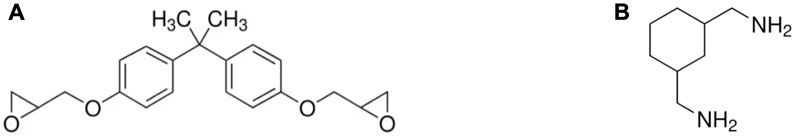
Figure 1. Molecule structure of (A) Bisphenol-A diglycidyl ether (CAS 1675-54-3) and (B) cycloaliphatic amine (CAS 2579-20-6).
The fabrication process of the plastic scintillator, as illustrated in Figure 2, was conducted by dissolving the primary and secondary dopants into the low-viscosity hardener B, assisted by heating to 70°C and stirring. After the dopants were dissolved, the mixture was cooled to 40°C, then the hardener B-dopant mixture was combined with epoxy A and left to cure for 24 h to form a hard solid polymer. In this experiment, the ratio of primary and secondary dopants was varied, as shown in Table 1.
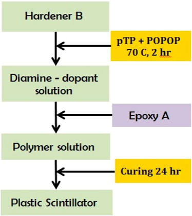
Figure 2. Schematic process of epoxy-based scintillator fabrication.
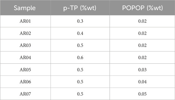
Table 1. The ratio of dopans on epoxy-based scintillators.
Table 1 presents the ratio of dopant components in plastic scintillator samples labeled from AR01 to AR07, measured in weight percentage (% wt). The observed dopant components are p-TP and POPOP. The data shows variations in the ratio between these two components across different samples. This information can be used to understand how dopant compositions affect the performance of the plastic scintillator in particle and radiation detection, with p-TP ratios ranging from 0.3% to 0.6% and POPOP ratios ranging from 0.02% to 0.05%.
To examine the functional groups present in the epoxy before and after curing, FTIR analysis was conducted. Spectra were obtained in the 500–4,000 cm-1 frequency range using the reflectance technique with KBr prism in a spectrometer (Bruker-Tensor II).
The morphology of the plastic scintillator sample were assessed by SEM (Hitachi SU3500), with high-vacuum backscattered electron images obtained using polished samples at 10 kV.
Differential scanning calorimetry (DSC) was performed using a simultaneous thermal analyzer (STA) Labsys, where samples of approximately 25 mg were placed in aluminum cartridges and samples were heated to 300°C at a rate of 10°C min-1.
The absorption spectra of a scintillator sample was analyzed utilizing the Hitachi UH5300 UV-Vis Spectrophotometer. This instrument was employed to determine the absorbance of the sample by measuring the wavelength in both the ultraviolet (UV) region (200–350 nm) and visible light region (350–800 nm).
The emission spectra of p-TP and POPOP dissolved in an epoxy matrix was evaluated by the Fluorescence Spectrophotometer FluoroMax—Horiba. The measurement was performed over a wavelength range of 350–600 nm.
A gamma spectra analysis was conducted using the gamma detector module Figure 3, assembled following the experimental apparatus scheme Figure 4, which comprised of (1) gamma source 137Cs (4.86 μCi), (2) a scintillator sample placed in an aluminum tube, (3) the Hamamatsu R878 PMT (also in an aluminum tube), (4) the Gamma Spectacular MCA GS-PRO, and (5) data acquisition by the computer. The gamma sources was measured at 2 cm perpendicular to the center of scintillator sample, and scintillator was attached to the window of the PMT using optical grease. Each measurement is repeated three times for 300 s. This analysis will present the number of gamma photon counts passing through the scintillator and the Compton spectra resulting from the interaction of photons and polymer material.
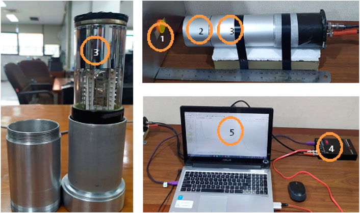
Figure 3. Experimental setup based on Figure 4.
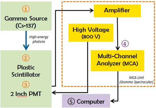
Figure 4. Schematic for gamma spectra evaluation.
Figure 5 shows the FTIR spectra of epoxy before and after curing. When epoxy resin is mixed with a hardener, a chemical reaction occurs that results in the formation of a cross-linked network structure. This reaction involves the opening of the epoxide ring in the resin and the formation of covalent bonds between the resin and hardener molecules, which creates a three-dimensional network of interconnected chains. As a result of this cross-linking reaction, the cured epoxy will exhibit new peaks in its Infrared (IR) spectra that are associated with the chemical bonds that are formed during the reaction. For example, the stretching vibrations of C-O and C-N bonds may be observed in the cured epoxy spectra, which are indicative of the new bonds that have been formed between the resin and hardener molecules [12].
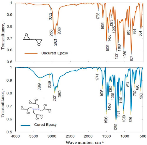
Figure 5. FTIR spectra of uncured and cured epoxy.
After the epoxy is cured, there is evidence of absorption at Wave number 3309 cm-1, which is caused by the stretching vibrations of -NH2 and -OH groups [13]. The spectra of the cured epoxy show a wide band at 3,309 cm−1, indicating N-H stretching, and another band at 1,605 cm−1, indicating N-H bending. There are also bands at 2,956 cm−1 and 2,921 cm−1, which correspond to the stretching of asymmetrical C-H bonds for CH3 and CH2, respectively. The bands at 1,505 cm−1 and 1,375 cm−1 indicate CH3 deformation mode, while the band at 1,455 cm−1 shows CH2 deformation mode.
The spectra indicate the presence of the ring structure of the epoxy, and changes to this structure resulting from the reaction with the hardener can be observed in the 1,300–1,000 cm−1 range. The spectra also show peaks at 2,866 cm−1 and 1,180 cm−1, indicating aldehyde C-H stretching and C-O stretching, respectively. The peak at 910 cm−1, which is characteristic of the epoxide ring in uncured epoxy, disappears, confirming the curing reaction between the epoxy and the amine groups of the curing agent [12, 14]. The IR spectra of cured epoxy show a decrease in the intensity of the peak associated with the epoxy group, at around 910 cm-1, and a peak at around 1,107 cm-1, which confirms the presence of amine linkages formed during the cross-linking reaction. Table 2 provides further details on the FTIR spectra of the epoxy [15, 16].
Table 2. IR band of Epoxy.
Table 2 presents information about the infrared spectrum of epoxy compounds, displaying characteristic peaks and bond assignments within the molecule. The recorded peaks include N-H, C-H, C=C, C-C, C-O-C, and C-O stretching vibrations, as well as in-plane and out-of-plane C-H deformations. This data is crucial for identifying the components and molecular structure of epoxy compounds and characterizing their chemical functionality.
According to the FTIR analysis, it has been verified that a cross-linking reaction has taken place and the aromatic compounds have bonded together to create lengthy polymer chains, which have transformed the solution into a solid state. The density of the solid was measured to be 1.04, which is similar to that of polystyrene. The presence of aromatic chains in plastic scintillators plays a crucial role in the scintillation process by providing a high-concentration of aromatic rings that efficiently converts high-energy radiation into visible light signals [17].
The process of manufacturing an epoxy-based plastic scintillator is presented in Figure 6, which displays a scintillator with a diameter of 50 mm and a thickness of 50 mm. The scintillator includes a primary dopant of p-TP and a secondary dopant of POPOP dissolved in the epoxy. Figure 6A depicts the photoluminescence effect of the scintillator when exposed to UV light, whereas Figure 6B illustrates a scintillator sample that has been coated with an aluminum foil reflector and a black ribbon shield. The visual observation that the plastic scintillator made of epoxy is less transparent than commercial plastic scintillator. There are also white dots of the dopants visible inside the scintillator, possibly because the dopants were not fully dissolved during the mixing process. Additionally, microbubbles are visible on the walls of the scintillator cylinder, which may have formed during the exothermic epoxy curing process.
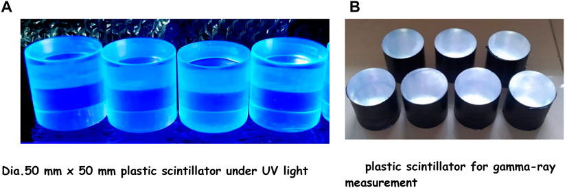
Figure 6. Photograph of epoxy based. (A) Dia. 50 mm x 50 mm plastic scintillator under UV light. (B) plastic scintillator for gamma-ray measurement.
The surface morphology of an amorphous polymer, such as epoxy, can be observed using scanning electron microscopy (SEM). To prevent the charging effect, coating is carried out using Au on the surface of the scintillator plastic sample. Amorphous polymers have a disordered, random arrangement of their molecular chains, and this can be reflected in their surface morphology. Figure 7A show the surface of an amorphous polymer often appears smooth, with a uniform texture that lacks any discernible patterns or features. There are small bumps or protrusions, or areas of the surface that appear rougher or more textured due to the presence of p-TP and POPOP as dopans. The white specks are thought to be luminescent material dispersed in the epoxy matrix. This can be seen when mixing the PTP/POPOP luminescent material in the matrix.
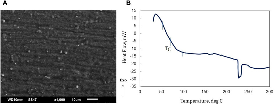
Figure 7. (A) SEM images of the epoxy based scintillator, (B) DSC curve of epoxy-based scintillator Emission and absorption wavelength.
The white specks, appearing as small bumps or protrusions, are presumed to be dopants distributed within the polymer matrix. This phenomenon is also noticeable when the dopant is dissolved in a liquid resin prior to polymerization (crosslinking). Even during the dissolution process, the dispersed dopant remains visually detectable. Although individual molecules at the nano size are not directly observable, the scanning electron microscopy (SEM) results reveal the presence of small bumps within the range of 1–5 μm.
Figure 7B in the DSC results depicts that, following the completion of the hardening procedure, the epoxy polymer showcases a glass transition temperature (Tg) spanning from 50°C to 100°C. As heat is absorbed (an endothermic process), the epoxy polymer commences its melting phase within the temperature interval of 220°C–244°C, with the melting peak process occurring at 228°C. A discontinuous condition around 240 indicates the melting point of the epoxy matrix. In the range of 240°C it is estimated that there will be a phase change due to melting. At the melting point, the solid phase changes to liquid, while at the glass transition temperature there is no phase change, but the polymer matrix softens/becomes soft. The epoxy substance exhibits a property of becoming more pliable when exposed to temperatures approximately around 70°C. Thus, when employing this material for radiation portal monitors, it becomes crucial to integrate a cooling system to prevent the temperature from exceeding 50°C. As a comparison, the soften temperature of a polystyrene-based scintillator which is commonly used for RPM is 75°C [18].
Figure 8 shows the results of the emission spectra based on the concentration of p-TP and PPO. In Figure 8A, although the concentration of p-TP increases, the emission spectra does not show a consistent trend, and the maximum intensity is obtained at 0.5 wt% p-TP. The addition of p-TP from 0.3% to 0.5% (POPOP remains 0.02%) has the effect of increasing emission intensity, but more than that the epoxy solution becomes cloudy/less transparent which results in a decrease in intensity. The same trend is observed in Figure 8B with an increase in POPOP concentration, with the maximum intensity at 0.03 wt% POPOP. The changes in POPOP concentration, where the solution becomes less transparent above a concentration of 0.03% which results in a decrease in emission intensity.
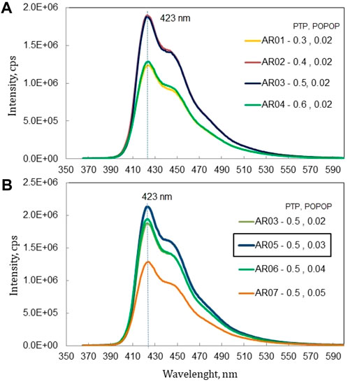
Figure 8. Emission spectra of epoxy based scintillator with (A) variation weight of p-TP and (B) variation weight of POPOP.
In all samples, emission was observed in 400–500 nm at a peak wavelength of 423 nm, which was attributed to the influence of the secondary dopant POPOP, which emitted at that wavelength [19]. This peak at 423 nm corresponds to the performance of a PMT in obtaining maximum quantum efficiency [20].
Figure 9A shows the emission spectra of epoxy-based scintillator excited by wavelengths of 280 nm, 300 nm, 320 nm, and 350 nm. Figure 9B illustrates the outcomes of combining the absorption and emission spectra of the fabricated scintillator. The absorption wavelength of p-TP is within the range 220–300 nm (peak at 270 nm) and is emitted within the range 290–400 nm (peak at 338 nm), as reported in past literature [21]. The emission spectra of p-TP and the absorption spectra of POPOP occur in almost the same wavelength within the range 290–400 nm. Absorption edge at 380 nm as shown in Figure 9B is caused by POPOP in the matrix, and then re-emitted within the wavelength range 400–500 nm (peak at 423 nm).
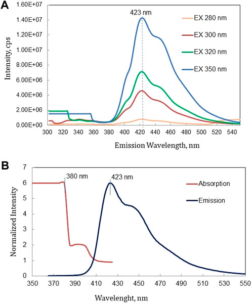
Figure 9. (A) Emission spectra excited at various wavelengths and (B) Absorption and emission spectra of epoxy based scintillator.
This measurement involves using a PMT that operates at 800 V and has an amplifier inside it to amplify the electrical signal generated by the PMT. The amplified signal is then processed by an MCA, which measures the amplitude of the signal and assigns it to a particular channel in the MCA spectra. The number of counts in each channel of the MCA spectra represents the number of photons that were detected with a particular energy or wavelength. The gamma spectra of three scintillator samples processed by MCA with a measurement time of 300 s are shown in Figure 10A. Figure 10B shows the gamma spectra of a commercial plastic scintillator (EPIC) under the same measurement conditions.
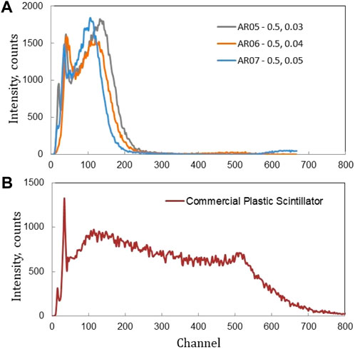
Figure 10. The spectra of (A) samples and (B) commercial scintillator obtained by 137Cs.
The interaction of gamma rays striking organic materials is dominated by the Compton scattering phenomenon. Some of the gamma energy is absorbed by electrons in the material, some is scattered as photons with a larger wavelength, captured by the PMT sensor and converted into current in the channel. The channel is proportional to the photon energy. In this study, the Compton edge sample (AR05) falls on channel 140, while the commercial scintillator falls on channel 506. Even though both respond to gamma rays from the 137Cs source, the character of the epoxy matrix for the commercial sample and polystyrene produces their own distinctive spectra.
Figures 10A,B show that the epoxy-based scintillator produces low light output due to lower transparency relative to the commercial scintillator. Low transparency results in photons that are not transmitted to the PMT or, if they are transmitted, only produce low pulse shapes that will enter the low channel.
Scintillation light output were measured on the fabricated epoxy-based scintillator and commercial plastic scintillator. Light output can be determined through a comparison between the peak of a single photoelectron spectrum and the specific point of energy spectrum, e.g., Compton edge. Both of the peak points are measured under gain of amplifier. Light output is calculated by Eq. 1 [8, 22]:
Where PPe is the Compton edge peak point of the 137Cs gamma source (Eq. 1), PP1phe is peak point of single photoelectron, Ke is the gain of the amplifier (in this experiment Ke = 10), K1phe is single photoelectron amplifier gain (K1phe = 1,000), Eγ is Compton edge energy of 137Cs (Eγ = 0.477 MeV) and QE represent the quantum efficiency of PMT. Quantum efficiency is determined by Eq. 2 [23]:
Here (Eq. 2), S is the radiant sensitivity of PMT (for Hamamatsu R878, S = 0.09 A/W), and λ is the emission wavelength (for sample scintillator λmax = 423 nm, and commercial scintillator λmax = 415 nm).
Table 3 shows the calculated light output of epoxy-based and commercial (EPIC) scintillators. The fabricated epoxy–based scintillators demonstrated a light output approximately 59%–64% of the EPIC scintillator’s output. To increase the light output of scintillator, La0.6Ce0.4F3 nanoparticles [24] and α-methyl- naphthalene [25] can be added during the dopant dissolution process in the matrix.
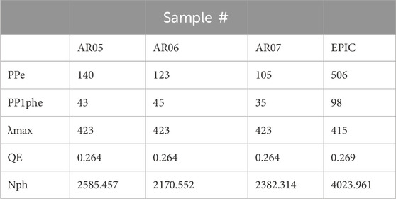
Table 3. Light output of the epoxy-based and commercial scintillators.
The study we conducted was to obtain data on the characteristics of an epoxy-based scintillator for the Radiation Portal Monitor application. This RPM will measure the gross gamma source, namely, the number of high energy gamma photon counts. The evaluation results of gamma spectrum measurements show that the sample is able to respond to a gamma source even with a yield of 64%. RPM requires a large volume scintillator of 5 × 10 × 200 cm3, so this epoxy-based scintillator will be an economical candidate.
In conclusion, the FTIR spectra of the epoxy-based scintillator showed that the curing process resulted in the formation of a cross-linked network structure, causing the aromatic compounds to form long polymer chains. The plastic scintillator made of epoxy was less transparent than commercial plastic scintillators, and microbubbles were observed on the walls of the scintillator cylinder. The SEM image showed that the surface of the amorphous polymer epoxy appeared smooth, with small bumps or protrusions due to the presence of p-TP and POPOP dopants. In the characterization of the Differential scanning calorimetry (DSC), and scanning electron microscope (SEM), it is evident that the character of the sample (epoxy + dopants) is predominantly determined by the epoxy matrix. The added aromatic dopants do not undergo chemical reactions but are only dispersed within the matrix. Any chemical changes would be reflected in the FTIR and DSC analyses through observable alterations in IR absorption. The emission spectra of p-TP and the absorption spectra of POPOP occur in almost the same wavelength within the range 290–400 nm. Absorption edge at 380 nm is caused by POPOP in the matrix, and then re-emitted within the wavelength range 400–500 nm with a peak at 423 nm, which corresponds to the performance of a PMT in obtaining maximum quantum efficiency. The epoxy-based scintillator with a 0.5% p-TP and 0.03% POPOP composition had the best performance. The fabricated epoxy–based scintillators demonstrated a light output approximately 59%–64% of the EPIC scintillator’s output. From this study, it is concluded that low-cost fabricated epoxy, with the addition of dopants, can provide a detection response to gamma rays. The study also contributes to a better understanding of the scintillation mechanism in the epoxy matrix and suggests that by altering its fabrication, transparency and light output can be enhanced to make it suitable for use in Radiation Portal Monitor (RPM).
MP: Conceptualization, Investigation, Writing–original draft. HN: Project administration, Resources, Writing–original draft. AP: Validation, Visualization, Writing–original draft, Writing–review and editing. AM: Investigation, Methodology, Supervision, Writing–review and editing. AJ: Formal Analysis, Software, Writing–original draft. AY: Data curation, Formal Analysis, Writing–original draft. KASMUDIN: Methodology, Project administration, Visualization, Writing–original draft. Utomo: Formal Analysis, Resources, Writing–original draft. RD: Formal Analysis, Funding acquisition, Writing–original draft. AS: Software, Supervision, Writing–original draft.
The author(s) declare financial support was received for the research, authorship, and/or publication of this article. The research was funded by a research grant at the National Research and Innovation Agency 2023.
The authors declare that the research was conducted in the absence of any commercial or financial relationships that could be construed as a potential conflict of interest.
All claims expressed in this article are solely those of the authors and do not necessarily represent those of their affiliated organizations, or those of the publisher, the editors and the reviewers. Any product that may be evaluated in this article, or claim that may be made by its manufacturer, is not guaranteed or endorsed by the publisher.
2. Birks JB The theory and practice of scintillation counting. New York U.S.A: Pergamon Press (1964).
3. Lee CH, Son J, Kim T, Kim YK. Characteristics of plastic scintillators fabricated by a polymerization reaction. Nucl Eng Technol (2016) 49:592–7. doi:10.1016/j.net.2016.10.001
5. Ahmed GS, Farag AT Development of a compact radiation detection system based on the use of silicon photomultipliers. Aust J Basic Appl Sci (2017) 11:159–66.
6. geon Kim D, Lee S, Park J, Son J, Kim TH, Kim YH, et al. Performance of 3D printed plastic scintillators for gamma-ray detection. Nucl Eng Technol (2020) 52(12):2910–7. doi:10.1016/j.net.2020.05.030
7. Mukhopadhyay S. Plastic gamma sensors: an application in detection of radioisotopes. Proc SPIE - Int Soc Opt Eng (2005) 5198.
8. Kang H, Min S, Seo B, Roh C, Hong S, Cheong JH. Low energy beta emitter measurement: a review. Chemosensors (2020) 8(4):106–42. doi:10.3390/chemosensors8040106
9. Xu Y, Deng H, Lei H, Chang G. Initiator-free preparation and properties of polystyrene-based plastic scintillators. J Polym Res (2019) 26(8):177–9. doi:10.1007/s10965-019-1838-x
10. Alex L, Paulraj R, Tyagi M. Effect of PPO and POPOP activators on the scintillation performance of polystyrene-based scintillator. J Optoelectron Adv Mater (2022) 24(7–8):365–71.
11. Nam JS, Choi YS, Hong SB, Seo BK, Moon JK, Choi JW. Study on the characteristics of a scintillator for beta-ray detection using epoxy resin. EPJ Web Conf (2017) 153:07005–6. doi:10.1051/epjconf/201715307005
12. Sabu M, Bementa E, Jaya Vinse Ruban Y, Ginil Mon S. A novel analysis of the dielectric properties of hybrid epoxy composites. Adv Compos Hybrid Mater (2020) 3(3):325–35. doi:10.1007/s42114-020-00166-0
13. Sahmetlioglu E, Mart H, Yuruk H, Surme Y. Synthesis and characterization of oligosalicylaldehyde-based epoxy resins. Chem Pap (2006) 60(1):65–8. doi:10.2478/s11696-006-0012-1
14. Dixit V, Nagpal AK, Singhal R. Synthesis and characterization of phenoxy modified epoxy blends. Malaysian Polym J (2010) 5(2):69–83.
15. Ramírez-Herrera CA, Cruz-Cruz I, Jiménez-Cedeño IH, Martínez-Romero O, Elías-Zúñiga A. Influence of the epoxy resin process parameters on the mechanical properties of produced bidirectional [±45°] carbon/epoxy woven composites. Polymers (Basel) (2021) 13(8):1273. doi:10.3390/polym13081273
16. González MG, Cabanelas JC, Baselga J. Applications of FTIR on epoxy resins - identification, monitoring the curing process, phase separation and water uptake. Infrared Spectrosc - Mater Sci Eng Technol (2012) 2:261–84.
17. Wieczorek A. Doctoral Dissertation: development of novel plastic scintillators based on polyvinyltoluene for the hybrid J-PET/MR tomograph. Jagiellonian University (2017).
18. Epic. Epic crystal (2022). Available at: https://www.epic-crystal.com/others/plastic-scintillator.html (Accessed February 20, 2022).
19. Chakraborty S, Harris K, Huang M. Photoluminescence properties of polystyrene-hosted fluorophore thin films. AIP Adv (2016) 6(12). doi:10.1063/1.4972989
20. Aguilar-Arevalo AA, et al. Letter of Intent: a new investigation of numu to nue oscillations with improved sensitivity in an enhanced MiniBooNE experiment (2012).
21. Artikov A, Baranov V, Boikov A, Budagov Y, Vasilyev I, Glagolev V, et al. Investigation of light collection in scintillation cubes of the SFGD detector. Phys Part Nucl Lett (2022) 19(6):784–91. doi:10.1134/s1547477122060036
22. Kim D-G, Lee S, Park J, Son J, Kim Y, Kim Y. Characteristics of 3D printed plastic scintillator. EPJ Web Conf (2020) 225:01005. doi:10.1051/epjconf/202022501005
24. Sahi S, Groza M, Zhang W, Do P, Kenarangui R, Burger A, et al. High-loaded and transparent LaxCe1-xF3 — polystyrene nanocomposite scintillators for radiation detection. Can J Chem (2017) 95(11):1233–40. doi:10.1139/cjc-2017-0211
Keywords: plastic scintillator, epoxy, characterization, performance evaluation, radiation detection
Citation: Pancoko M, Nuri HL, Prasetyo A, Manaf A, Jami A, Yanto AR, Kasmudin , Utomo , Djokorayono R and Suntoro A (2024) Characterization and performance evaluation of epoxy-based plastic scintillators for gamma ray detection. Front. Phys. 12:1289759. doi: 10.3389/fphy.2024.1289759
Received: 06 September 2023; Accepted: 18 March 2024;
Published: 10 June 2024.
Edited by:
Carlotta Trigila, University of California, United StatesReviewed by:
Weronika Wiktoria Wolszczak, Berkeley Lab (DOE), United StatesCopyright © 2024 Pancoko, Nuri, Prasetyo, Manaf, Jami, Yanto, Kasmudin, Utomo, Djokorayono and Suntoro. This is an open-access article distributed under the terms of the Creative Commons Attribution License (CC BY). The use, distribution or reproduction in other forums is permitted, provided the original author(s) and the copyright owner(s) are credited and that the original publication in this journal is cited, in accordance with accepted academic practice. No use, distribution or reproduction is permitted which does not comply with these terms.
*Correspondence: Andjar Prasetyo, c3R1ZGlkYWVyYWhAZ21haWwuY29t
Disclaimer: All claims expressed in this article are solely those of the authors and do not necessarily represent those of their affiliated organizations, or those of the publisher, the editors and the reviewers. Any product that may be evaluated in this article or claim that may be made by its manufacturer is not guaranteed or endorsed by the publisher.
Research integrity at Frontiers
Learn more about the work of our research integrity team to safeguard the quality of each article we publish.