
94% of researchers rate our articles as excellent or good
Learn more about the work of our research integrity team to safeguard the quality of each article we publish.
Find out more
TECHNOLOGY AND CODE article
Front. Phys., 11 January 2024
Sec. High-Energy and Astroparticle Physics
Volume 11 - 2023 | https://doi.org/10.3389/fphy.2023.1319879
This article is part of the Research TopicScience And Technology In Deep Underground LaboratoriesView all 19 articles
 Philippe Camus1†Jonathan Corbett1Sean Crawford1Koby Dering1Eleanor Fascione1,2Gilles Gerbier1
 Richard Germond1,2†
 Muad Ghaith1†
 Jeter Hall3,4,5
 Ziqing Hong4Andrew Kubik3,4Adam Mayer2†Serge Nagorny1Payam Pakarha1
 Wolfgang Rau1,2*
 Silvia Scorza3,4,5†Ryan Underwood1,2
Low-temperature cryogenics open the door for a range of interesting technologies based on features like superconductivity and superfluidity, low-temperature phase transitions or the low heat capacity of non-metals in the milli-Kelvin range. Devices based on these technologies are often sensitive to small energy depositions as can be caused by environmental radiation. The Cryogenic Underground TEst facility (CUTE) at SNOLAB is a platform for testing and operating cryogenic devices in an environment with low levels of background. The large experimental chamber (
Cryogenic particle detectors are among the detectors with the best energy resolution, capable of reaching eV-scale thresholds in small (typically gram-scale) devices (see, e.g., [1–4]). When combined with intrinsic amplification, this can extend to devices up to the kilogram scale [5, 6]. In small devices, intrinsic amplification can push the threshold well below an eV [7]. Hence, this is often the technology of choice for detecting sub-keV interactions. One important consideration when using cryogenic detectors is that thermal processes are generally slow (ms time scale) compared to other particle-detection technologies (e.g., ionization or scintillation with time scales of μs or faster). In massive detectors (kg scale) the typical environmental radiation background generates interactions at rates of tens of Hz. The combination of high event rate and slow response time would lead to overlapping events (pile-up) which in turn would severely limit the usefulness of such detectors. Hence, a low-radiation environment is required for experiments using this technology. Finally, high energy cosmogenic radiation is not only a direct source of background, but can also generate long-lived radioactive isotopes in the detector or surrounding material (cosmogenic activation, see, e.g., [8]). Thus, extended exposure of the detector material to cosmogenic radiation may limit the sensitivity of experiments that rely on very low background.
The Super Cryogenic Dark Matter Search experiment (SuperCDMS) [9] is presently under construction at SNOLAB, a deep underground laboratory hosted inside the active Vale Creighton mine near Sudbury, ON, Canada. It combines all the above requirements: massive cryogenic detectors with a low energy threshold are used to search for rare interactions of dark matter particles, and the detectors and the experimental apparatus of SuperCDMS are comprised of materials that get easily activated by cosmogenic radiation [8]. This motivated the design and construction of the Cryogenic Underground TEst facility (CUTE) at SNOLAB [10, 11]. CUTE enables the testing of the new SuperCDMS detectors under low-background conditions while mitigating the risk of cosmogenic activation.
From the beginning, consideration was given to a possible use of the facility after the primary goal of testing SuperCDMS detectors would be concluded. This informed a number of design choices that now make this a convenient facility for testing and operating not only particle detectors, but also other devices with low operating temperature that benefit from (or require) very low levels of background radiation. In 2021, SNOLAB has taken on the responsibility of maintaining and upgrading the facility and will be making it available to new users based on the merit of their proposals.
In this paper, we introduce the design considerations for the facility and describe its different components and subsystems and their performance, before ending with a short discussion of possible uses that might benefit from the special conditions provided by CUTE. The focus is on the facility as such, but where appropriate we will give examples of specific solutions implemented for SuperCDMS.
The original motivation for the CUTE facility was to test the new detectors that will be used in the upcoming SuperCDMS SNOLAB experiment [12]. Besides understanding basic detector parameters, a number of calibration measurements are planned, including a measurement to study the neutron-gamma discrimination power of the detectors with a sensitivity of better than 10–6 (meaning that the measurement would reveal if more than one in 106 gamma interactions were misidentified as neutron interactions). The minimal requirements for the facility are defined by the needs for operating these detectors and the necessity that the calibration measurements can be conducted without major interference from background radiation.
The SuperCDMS detectors consist of cylindrical germanium or silicon crystals, 10 cm in diameter and 3.3 cm thick (corresponding to a mass of 1.4 and 0.6 kg respectively), instrumented with superconducting transition-edge sensors (TESs) that require an operational temperature below about 30 mK [12]. Extended operation at such temperatures require a dilution refrigerator. The detectors come in two denominations: interleaved Z-sensitive Ionization and Phonon (iZIP) detectors and high-voltage (HV) detectors. iZIP detectors measure both phonons and charges for optimal background identification and discrimination An earlier incarnation of this detector type is described in [13]. HV detectors are operated with a bias voltage on the order of 100 V (compared to just a few Volts for the iZIPs). The Neganov-Trofimov-Luke effect [14, 15] leads to a significant increase of the phonon signal which in turn yields a low effective energy threshold. The detectors are arranged in stacks of six, attached to a structure that provides the mechanical, thermal and electrical connections and includes the central elements of the first-stage amplifiers. The complete assembly has a mass of up to ∼ 20 kg and is referred to as a tower. The tower without the detectors is called the tower body and the electronic elements attached to the tower are referred to as cold electronics. The sensors and some elements of the cold electronics require a low magnetic field of ideally ≲ 1 μT.
For calibrating these detectors, the maximum beneficial rate is about 7 Hz before being limited by pile-up. To enable a good signal-to-background rate during calibration, the overall background rate would therefore need to be ≪ 1 Hz. The limitation on the detector rate means that the maximum number of gamma interactions accumulated per day is a few times 106. Therefore, to achieve the goal sensitivity of 10–6 for the neutron-gamma discrimination measurement, the background neutron rate needs to be less than one neutron interaction per day per detector in the energy range of interest (∼1–50 keV).
To reduce the rate of cosmogenic radiation, the facility is located 2 km underground at SNOLAB near Sudbury ON. This in turn reduces the otherwise prohibitively high cosmic-ray induced neutron flux [16] and protects the detectors from cosmogenic activation. Additional shielding is necessary to reduce the environmental radiogenic neutron and gamma flux [17]. Also, measures were taken to avoid introducing contaminants into the experimental setup. We decided early on in the planning process to take further steps towards a considerably lower background level. The additional effort to accomplish this was modest and it gives the best perspective for a useful life of the facility after the completion of the SuperCDMS tests.
Other considerations during the design process included the strong susceptibility of the SuperCDMS detectors to mechanical vibration, due to their large mass, and the susceptibility of the readout electronics to electromagnetic interference. In addition to providing the right environment for the measurement, it is essential that the installation of the detectors into the facility does not significantly increase their exposure to contaminants such as dust or radon. Hence, a dedicated cleanroom with a low-radon air supply to host the cryostat for payload changes is an important part of the facility.
The CUTE cryostat is cooled by a cryogen-free (dry) dilution refrigerator from CryoConcept, with a base temperature of approximately 12 mK. The cryostat has six thermal stages with nominal temperatures of 300 K, 50 K, 4 K, 1 K, 100 mK, and 10 mK, respectively. The lowest three stages are referred to as the Still (ST), Cold Plate (CP) and Mixing Chamber (MC) stages, after the respective functional components of the dilution refrigerator. The other two cold stages are referred to as 4K and 50 K stages. Mechanical connections between the stages are made by stainless steel or G10 standoffs which provide solid structural connections with low thermal conductivity. The room-temperature stage consists of a stainless-steel vacuum vessel referred to as the Outer Vacuum Can (OVC). Copper cans acting as thermal radiation shields are mounted on the 50K, 4K, and Still stages. The 50 K can is wrapped in multiple layers of aluminized Mylar super-insulation to reduce the thermal load from the OVC. A separate experimental stage is mechanically and thermally anchored to the MC stage with three copper bars, providing a large volume (∼25 cm diameter and 30 cm high) for the experimental payload.
The 50K and 4 K stages are cooled by a pulse-tube cryocooler (PTC), while the lower thermal stages are cooled by the dilution unit (DU). In order to minimize the coupling of vibrations from the PTC into the cryostat, CryoConcept developed a technique that avoids mechanical connections between the cold stages of the PTC and the cryostat (the Ultra-Quiet Technology™, UQT). Thermal contact is instead provided by the helium mixture that pumped out of the Still. This is achieved by installing the PTC’s cold head inside the Still pumping line of the DU. Gold-plated copper disks with a concentric ring structure mounted on the cold head stages are interleaved with corresponding disks that are connected to the 50K and 4 K stages of the cryostat. This compact design provides a large effective heat transfer surface and a narrow gas gap (∼1 mm) as the circulating gas meanders through the ring structure.
The cool-down process includes two distinct steps, the precooling and the condensation. During the precooling, helium is circulated past the PTC before infusing the DU while bypassing the main impedance. This step takes roughly 3 days and cools the DU to ≲ 4 K. In the second step, the 3He/4He-mixture is condensed in to the refrigerator, starting the main cooling cycle. The base temperature (11–12 mK without any payload) is reached about 8 h after the start of the condensing step. With a payload installed, the temperature typically settles at around 15 mK, before dropping slowly (time scale of weeks) to ∼ 12 mK (owed likely to not, or imperfectly, annealed Cu parts in the setup). The cooling power at 100 mK is ∼ 200 μW. The warm-up to room temperature takes nearly a week if the cryostat is left under vacuum; however, introducing of nitrogen gas into the OVC can reduce the warm-up time to less than 3 days.
The SuperCDMS detector tower body includes three thermal stages mirroring the three lower stages of the cryostat (MC, CP and ST). This allows the cold electronics and the wiring between the MC and ST stages to be mounted directly to the tower. The tower is installed by attaching its MC stage to the experimental stage of the cryostat. The detectors are above, and the tower body with the warmer thermal stages is below the experimental stage. A copper can (referred to as top hat) is mounted on the experimental stage, surrounding the detector stack to shield it against infrared radiation (IR) from higher temperature stages. It is made entirely from copper, held together and connected to the experimental stage by a total of only four screws; brazing or soldering was avoided as these techniques are known to add noticeable levels of radio-contaminants.
The thermal connection to the CP stage of the tower is provided by a braided and annealed copper heat-sink strap attached to a long copper bar which reaches from the CP stage of the cryostat to below the experimental stage. The Still stage of the tower is thermally connected to the bottom of the Still can by means of a ∼ 0.3 mm-thick copper membrane. This membrane also closes the Still can volume to prevent thermal radiation from the 4 K stage from entering. An undulation in the membrane halfway between the tower and the rim of the can allows for a few millimeter of relative vertical movement to avoid differential thermal contraction between the tower and the cryostat causing stress on the tower.
An extension to the 4 K can was designed and built out of copper and held together by screws only, again to avoid brazing and the related increase in radioactive background. This extension has a removable bottom lid and includes feedthroughs for the six readout cables for the SuperCDMS towers. These cables are guided up along the outside of the 4 K can. The feedthrough and the connection to the can provide the heat sinking to that stage. The cables are further heat-sunk at the 50 K stage before they are connected to the room-temperature vacuum feedthrough.
Figure 1 shows pictures of the MC top hat together with the experimental stage mounted on the MC bars, the Still membrane, and the 4 K extension with the IR blocking cable feedthroughs.
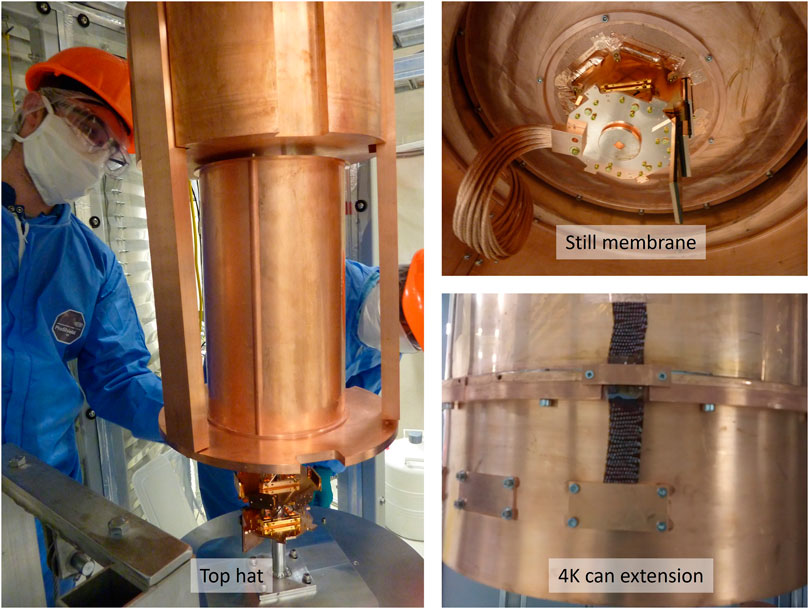
FIGURE 1. Left: The IR shield at the MC stage (top hat) is mounted on the experimental stage which in turn is attached to the cryostat by the 3 MC bars. Directly above the top hat is the internal lead shield (see Section 5 for more detail on the shield). The half-pipe shaped walls of the top hat sit in grooves in its top plate, the bottom ring and the connecting vertical rods, The whole assembly is held together with the two screws connecting the top plate to the rods and two screws that attach the top hat to the experimental stage (connecting through the bottom ring to the rods). Top right: The Still membrane with the visible circular undulation is mounted, connecting the bottom of the Still can to the Still stage of the SuperCDMS tower, acting as thermal link as well as closing off the Still volume to IR from the warmer thermal stages. Bottom right: The 4 K extension, consisting of a wall section with screwed-on flange and bottom plate. When needed, the cover plates in the walls are replaced by the easy-to-install IR-blocking cable feedthroughs (also shown in the picture).
The dilution refrigerator was delivered with the thermometry required for its operation and an additional unused twelve-pin vacuum feedthrough installed. This is being utilized for custom wiring for three additional thermometers. The wiring is routed to the MC stage of the cryostat and heat-sunk at the different thermal stages using custom-designed printed circuit boards that also act as IR blocking feedthroughs. Four-pin connectors at each feedthrough allow for easy connection of auxiliary thermometry at the desired thermal stage. In addition, a coaxial wiring solution for the future operation of sensors that require the transmission of high-frequency signals has been developed. An initial test showed that this wiring does not impact the cryogenic performance.
For payload changes, the cryostat needs to be moved from its operating location inside the shielding to the facility’s cleanroom. For this, all electrical, gas and vacuum connections need to be removed. The high-pressure helium hoses for the PTC are connected to the rotary valve using quick-connect style connections that automatically seal when disconnecting and minimize air inclusion when connecting. When the cryostat is placed inside the shielding, many of the other standard connection points are difficult to reach. Hence, all connections for the helium mixture and the cryostat vacuum were routed to a conveniently located connection plate which has manual valves to close off all the lines going to the cryostat. All lines that may get cold during operation (primarily during the precooling stage) are thermally insulated to minimize frost production and the subsequent dripping water after warming up. A multi-connector is used for conveniently connecting and disconnecting simultaneously all air-pressure lines for the pneumatic valves.
The turbomolecular pump which is part of the circulation system for the helium mixture is mounted on top of the refrigerator and requires cooling. The most common method of cooling with water bears a non-negligible risk of leaks due to the regular need to disconnect the lines. Therefore, cooling is provided instead by a Peltier cooler. The temperature of the cooler is regulated by a feedback control system. The original control circuit was based on medium-frequency switching of a high power line, leading to significant electromagnetic emission that interfered with the readout electronics. To mitigate this effect an alternate control was implemented that instead uses voltage control. The power supply is a high-frequency switching power supply where the switching frequency is above the bandwidth of the presently used readout electronics. This avoids the electromagnetic interference introduced by the original control circuit. If a future use of the facility is also susceptible to the interference from the high-frequency switching power supply, it can easily be replaced by a non-switching power supply. Figure 2 shows a top-view of the refrigerator when fully connected at its operating location inside a drywell in the centre of the shielding water tank (for more details of the facility layout see Section 5).
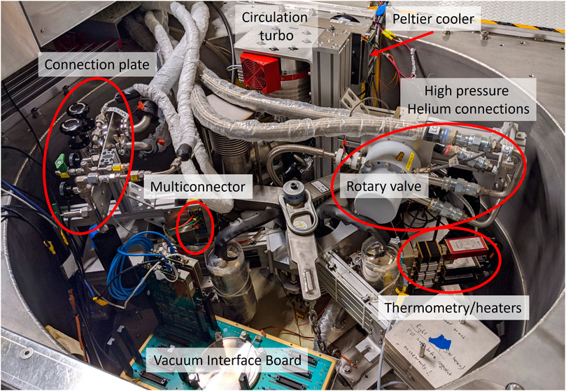
FIGURE 2. Top view of the cryostat when installed and fully connected in its operating location inside the drywell. Labelled in the picture are (starting near the centre and going clockwise): the multiconnector for the pressurized air lines for the pneumatic valves; the connection plate collecting all vacuum and helium-mixture lines that need to be disconnected for moving the fridge; the turbo pump for the helium mixture, and attached behind it the Peltier cooler; the connection points for the high-pressure helium lines, next to the rotary valve the thermometry and heater connections; and the Vacuum Interface Board (VIB) for connecting the SuperCDMS readout electronics.
The laboratory environment or the cryogenic equipment mounted on top of the refrigerator can be sources of vibrations. Several strategies are utilized to mitigate the transmission of such vibrations to the experimental stage. Typically, the pulse tube cooler’s rotary valve is the largest source of vibrations in a dry dilution refrigerator. The refrigerator used at CUTE features a double-frame design to effectively decouple the top with the rotary valve and the turbo pump from the lower part where the detectors are installed. The upper part is rigidly connected to the drywell, while the lower part is connected to a stainless steel frame, the suspension frame. The latter sits on three soft elastomer cup dampers (Newport ND20-A) as shown in Figure 3. The upper and lower parts of the refrigerator are connected only by the outer wall of the Still pumping line in form of a bellows with very low stiffness (16 N/mm along its axis and 167 N/mm laterally), effectively decoupling the two parts. The UQT discussed in Section 3 further minimizes the transmission of vibrations from the rotary valve of the PTC to the lower part of the cryostat.
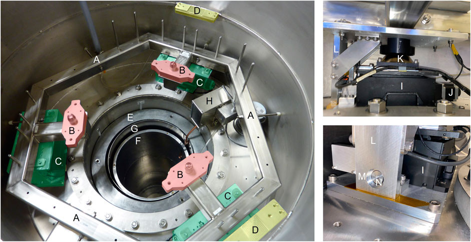
FIGURE 3. Left: The suspension system’s steel frame (A) with the mounting points for the cryostat [(B), red highlights] sits on three dampers (damper assemblies (C) highlighted in green) to mechanically isolate the cryostat from the vibrations transmitted through the drywell. Also visible are two of the mounting points (D) for the upper part of the refrigerator on the drywell (yellow highlights), as well as the shielding inside the lower part of the drywell (outer (E) and inner (F) layers of lead with a thin magnetic shield (G) in between; see Sec. 5). Located on the top right in the left picture is the gamma calibration system (H) (see Sec. 6). Top right: one of the three damper assemblies. A labjack (I) (black) driven by a stepper motor (J) (to the right of the labjack) sits on the drywell; the elastomer cup damper (K) is mounted on the movable stage of the labjack and carries the suspension frame. The positions of both, the movable labjack stage and the suspension frame are measured relative to the drywell (see text). Visible to the left of the labjack is a vertical aluminum bar (L) rigidly attached to the suspension frame. Right bottom: The vertical aluminum bar has a circular cutout (M). A rod (N) attached to the drywell penetrates this cutout with a nominal clearance of 1.0 mm all around, limiting the movement of the suspension frame relative to the drywell.
The low pressure inside the pumping line (
Due in part to the design of the ventilation system at SNOLAB, the pressure in the lab can fluctuate by up to ∼ 20% over the course of twenty to 30 minutes. The resulting time-varying force would lead to a change in position of the cryostat relative to the top part of the refrigerator given by the stiffness of the dampers (∼80 N/mm). This would change the cross section of the gas gap and hence impact the thermal profile of the cryostat: an increased gas gap improves the Still pumping efficiency, cooling it down, but reduces the thermal link between cold head and the 4K and 50 K stages of the cryostat. To compensate for the pressure variation, each of the three dampers supporting the suspension frame is mounted on the movable stage of a labjack. These stages are driven by stepper motors operated by a micro-controller. On one side of each damper assembly, there is a vertical aluminum bar mounted to the suspension system. Each of these bars has a cutout for a rod that is mounted on the drywell. The cutout is only marginally larger than the rod’s cross section, allowing for a maximal deviation of the actual position of the suspension frame from its nominal position by 1 mm (vertically and laterally). Such a tight tolerance is necessary to avoid a touch inside the cryostat between the cold stages of the PTC and the cryostat stages. In the lowest possible position, the three aluminum bars carry the full weight of suspension frame and cryostat, and the cryostat is no longer floating. To monitor the position of the suspension system and the state of the dampers, each damper assembly has an optical sensor and a Hall effect sensor. The optical sensors track the distance between the suspension frame and the drywell and thus the relative position of the two parts of the refrigerator. The Hall effect sensors are used to measure the position of the movable stage of the labjack. Together with the optical sensors, they are used to determine the compression of the dampers. This information is important as the performance of the dampers depends on their compression. A software-based feedback system maintains the relative position of suspension system and drywell and thus of the upper and lower parts of the cryostat; more information about the control algorithm of the suspension system is presented in Section 9.
The performance of the vibration isolation was verified using a prototype 1.4 kg, germanium SuperCDMS HV detector (referred to as G124), as these large sized detectors have been observed to be sensitive to vibration-induced noise. To separate vibrational noise from noise caused by electromagnetic interference, a transition-edge sensor (similar to the TESs of the SuperCDMS detectors) on a small silicon substrate (chip) was operated alongside G124. This device is far less sensitive to vibrational noise but more sensitive to electromagnetic interference. For these tests, the state of the suspension system was changed between its normal (balanced) configuration, and a coupled configuration where it was intentionally tilted to introduce a contact between the cold stage of the PTC and the cryostat. The presence and absence of the touch was verified by checking the electrical continuity between the pulse tube’s cold head and the cryostat which are normally electrically isolated. For each configuration, data from the detectors were collected with the PTC running and switched off. Figure 4 shows the noise power spectra of these tests for both G124 and the TES sensor on the chip. In the coupled state there is a noise difference at low frequency in G124 of almost a factor of forty between PTC on and off. In contrast, only a very small difference (order of 10%–20%) is observed in the balanced state. The noticeable difference for the TES chip between PTC on and off in the coupled state can be traced back to cross-talk in the readout between the two devices and is not related to actual noise in the TES chip: the excess noise disappeared when the sensor on G124 was made insensitive by increasing the readout current until the sensor went into its normal-conducting state, while no change was applied to the TES chip. The fact that the PTC-induced noise couples strongly to G124 and only weakly to the TES chip confirms that the majority of the effect is indeed caused by mechanical vibration; all other effects would be as strong if not stronger in the smaller device when compared to G124. The fact that the excess noise essentially disappears when the suspension system is balanced demonstrates the effectiveness of the system, even though this test is not suited to quantify the level of vibration reduction or residual vibrations.
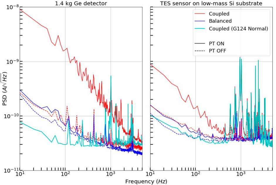
FIGURE 4. Noise power spectra under various conditions of the experimental setup from a 1.4-kg germanium detector (G124) and a small silicon substrate with a transition edge sensor (figure from [18]). Operating conditions include our main source of vibrations, the PTC (PT in the legend) being on and off with the suspension system in its normal operating mode (balanced) as well as tilted to introduce a mechanical (as well as electrical) connection between the PTC cold head and the cryostat (coupled). The latter condition was tested with G124 sensitive (sensor in its superconducting transition) as well as insensitive (sensor in normal-conducting state) but no change in the readout conditions of the small device. There is a drastic increase in noise in G124 in the coupled state when the PTC is turned on. The small sample also shows a significant increase, but only when G124 is sensitive, producing a large signal. When G124 is insensitive and thus does not produce a signal, the small device sees no significant difference between the coupled and balanced state. This shows that the increase in noise in the small sample is induced by the large signal from G124 (cross talk) rather than by the coupling. These findings support the hypothesis that the noise is indeed coupled through vibrations rather than electrically (the latter would have affected the small devices as much or more than the big one) and thus show the effectiveness of the suspension system.
For a more direct measurement of vibrations, a triaxial and a single-axis accelerometer are available. However, they are presently mounted on top of the cryostat (not inside), show a relatively high electronic noise level and there is indication that they pick up acoustic noise. Hence, some improvements will have to be implemented in order to use them for sensitive diagnostics. However, they were used to demonstrate that a high flow of purge gas in the drywell causes the cryostat to vibrate. The purge gas streams from the bottom to the top of the drywell past the cryostat to prevent radon-rich air from the lab to enter that space (see Section 5). The purge gas flow was reduced to a level where the vibrations caused are negligible (assessed by measurements with the accelerometer as well as a detector) while the radon level in the drywell stayed low [19].
Background radiation comes from various sources. Natural radioactive contaminants—mainly potassium (4 K) and the uranium U) and thorium (Th) decay chains—in the environment and the experimental setup itself produce high-energy gamma rays as well as neutrons via (α,n)-reactions and spontaneous fission. In the immediate vicinity of the sensitive components of the experiment, also short-range radiation such as alphas, betas, and low-energy gammas need to be considered. Lastly, cosmic radiation contributes muons, high-energy neutrons generated by muon interactions, and hadronic showers.
The approximately 2 km of rock-overburden at SNOLAB completely remove the hadronic component of the cosmic radiation and reduce the cosmic-ray muon flux by several orders of magnitude (to
The CUTE shielding was designed based on Monte Carlo simulations considering the attenuation of external radiation as well as the acceptable levels of contamination of the shielding materials. The outer layer of shielding consists of a water tank with a stainless steel drywell in the centre to host the cryostat. The water tank is filled with Ultra Pure Water (UPW) from the SNOLAB water purification plant and provides a shielding thickness of ∼ 1.5 m on the side and ∼ 1.0 m at the bottom, reducing the external gamma radiation by about a factor of 200 [20]. In regular intervals, the UPW is circulated through a container with bromine tablets to avoid biological growth in the water tank. This is scheduled for times when no measurements are taken with the facility to prevent possible electromagnetic interference caused by the water circulation pump. A deck structure holds the drywell in place and provides access to the top of the cryostat.
Inside the drywell, surrounding the cryostat, are two layers of lead. The outer layer has a thickness of 8.7 cm on the sides and 13 cm at the bottom and made from lead with a low activity of 210Pb; the inner layer (2 cm sides and bottom) is made from very-low activity lead1. Located between the two layers of lead is a μ-metal shield (from Amuneal, Philadelphia, USA) which reduces the static magnetic flux by about a factor of fifty at the centre of the cryostat. This is necessary because the full strength Earth magnetic field would impact the detectors’ performance and make it difficult or impossible to operate the SQUID-based preamplifiers used by SuperCDMS. The space between the inner lead layer and the cryostat is flushed with low-Rn air (
The setup as described so far shields the experimental space inside the cryostat well from radiation from the floor and walls, but the presence of the refrigerator necessarily generates a big opening on the top. This opening is closed by a 20 cm-thick polyethylene (PE) lid on the deck, mitigating neutrons from the top. The PE is encased in a stainless steel box and moves on rails to the side to provide access to the top of the refrigerator. Inside the cryostat, directly above the experimental volume is a 15 cm-thick layer of lead encased in copper. It shields the experimental volume from gamma radiation from above, including from contaminants inside the dilution refrigerator. The internal lead is thermally connected to the Still stage of the cryostat to avoid excess heat load on the experimental stage. A sketch of the experimental setup and a picture of the internal lead shielding are shown in Figure 5.
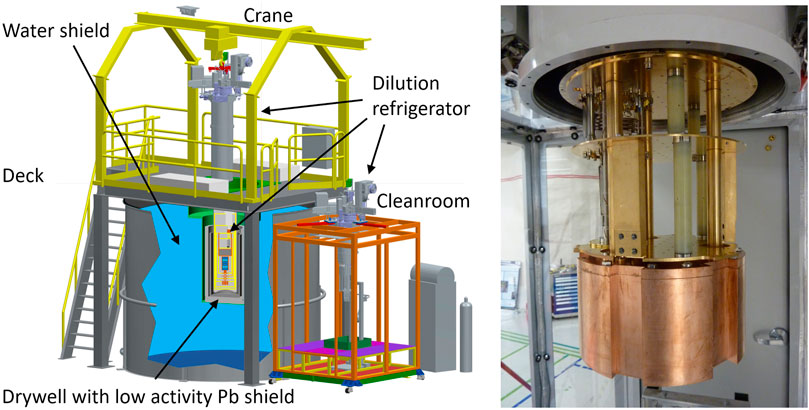
FIGURE 5. Left: Layout of CUTE facility. While in operation, the dilution refrigerator hosting the payload is located inside the drywell at the center of the ∼ 3.5 m-diameter water tank and surrounded by about 11 cm of lead for shielding against environmental radiation. The deck structure holds a 20 cm-thick polyethylene shield moderating neutrons coming from the top. It consists of two-halves and is mounted on rails so it can be moved to the sides, giving access to the top of the cryostat. A monorail crane moves the cryostat between the drywell and the low-radon cleanroom for payload changes. Right: Internal lead shield encased in copper, to block external gammas from the top. As it sits below the MC plate, and thus below all functional parts of the dilution refrigerator, it also block radiation from the dilution unit to the payload which would be mounted below the internal lead (see Figure 1). Mechanically and thermally the lead it is attached to the Still stage of the cryostat by three gold-plated copper rods that clear openings in the CP and MC plates of the fridge.
Most of the materials in use at CUTE were screened to assess their radioactive contamination levels. For the materials which were not screened, contamination levels of comparable materials from previous screening campaigns within the SuperCDMS experiment were considered.
To estimate the background budget of the facility, extensive Geant4 [21] Monte Carlo simulations were carried out. All the components of the facility were simulated considering all contaminants that were identified in the screening measurements. The gamma and neutron flux from the walls of the SNOLAB cavern are also simulated, considering the measured U, Th and 4 K contamination. The simulations framework was set to generate gammas and neutrons from the bulk of the materials inside the facility and the surfaces of the SNOLAB cavern walls.
While the Geant4 Monte Carlo simulation propagates the radiation particles through the different components of the setup, the normalization and conversion of simulated spectra into event rates is handled by Background Explorer [22], a tool originally developed by SuperCDMS and then adopted for CUTE. The energy spectra of events in a 600-g SuperCDMS germanium detector from the different simulated sources are shown in Figure 6.
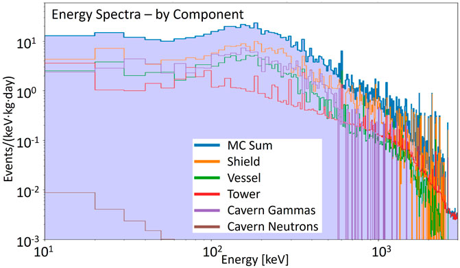
FIGURE 6. Energy spectra from Geant4 Monte Carlo simulations for different components of the background radiation in the CUTE facility for a 600-g SuperCDMS germanium detector. The sum of the contribution is shown in blue. “Vessel” refers to the cryostat components (including the internal shielding) while “Shield” includes all shielding components external to the cryostat. Note that most of the cryostat components had contamination levels below the sensitivity of the screening measurements and the values used in the simulation are the upper contamination limits from those measurements. The “Tower” energy spectrum refers to the radioactive background induced by the detector target material itself and the components of the detector tower structure. Nuclear recoils from radiogenic neutrons originating from the cavern wall contribute only a very small rate.
The sum of all components results in an event rate of 6.7 ± 0.8 events/keV/kg/day in the energy range from 1 to 1,000 keV which is in reasonably good agreement with initial measurements. About 10% of the rate is contributed by the detector stack itself. The major contributors to the background budget are the gammas from the SNOLAB cavern (∼30%), the inner layer of the external lead shield (∼20%) and the stainless steel of the OVC (∼13%). The nuclear recoil rate is expected to be less than half an event/kg/day in the range from 1 to 50 keV.
Most of the external gammas enter through the gaps between the external and internal lead shielding. If a lower gamma background is required for future measurements, an upgrade to the facility could improve the situation by adding additional gamma shielding to reduce those gaps, and replacing the highest contributors from the facility (inner layer of the external lead shield and OVC) with lower activity materials (lower activity lead for the shield and, e.g., copper for the OVC).
CUTE has two dedicated systems for the delivery of radioactive sources that can be used for calibration. A gamma calibration system was installed when the facility was first established; a neutron calibration system is presently in the process of being completed. In addition to these two systems that are both external to the cryostat, there is the possibility to install sources of radiation with low penetration inside the cryostat. An 55Fe X-ray source (∼6 keV) with an aluminum foil to generate X-ray fluorescence (∼1.5 keV) is presently available and has been used in CUTE. The use of other sources is possible as long as they comply with the SNOLAB-specific requirements for radioactive sources.
The gamma calibration system is based on a133Ba source with a design activity of 37 kBq. It emits gammas at different energy with the most prominent emission at 356 keV. According to SNOLAB requirements, the source is doubly encapsulated in addition to the manufacturer’s encapsulation, and it is attached to a beaded string (see left panel of Figure 7). This string in turn is attached to a constant-force retractor and its movement is controlled by a stepper motor. The system is installed inside the drywell, near the top of the cryostat. It includes a lead housing where the source is located when not in use. The source is pulled into the housing through a curved channel to ensure that there is no direct line of sight to the outside world when the source is in the storage location. With the ≥4 cm of Pb surrounding the source in all directions, the radiation outside is negligible (≪1 nSv/h). A sketch of the calibration system set up is shown in the middle panel of Figure 7.
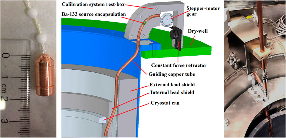
FIGURE 7. Left: Gamma calibration source (133Ba, 37 kBq nominal activity) with double encapsulation added beyond the manufactures encapsulation and attached to the beaded string. Middle: Gamma calibration system schematic. The source is stored in a lead housing located inside the drywell near the top of the cryostat. It is attached to a beaded string that is moved by a stepper motor (only its gear is shown) and spooled by a constant-force retractor. The copper tube guides the source into the space between the cryostat and its lead shielding (Figure adapted from [18]) Right: The gamma calibration system as presently implemented: installed at the rim of the lower part of the drywell, the stainless-steel box houses the lead shielding and the retraction and deployment system. Visible underneath is the copper tube that guides the source into the space between the cryostat (not in place when picture was taken) and the lead shielding (the inner layer of the lead shielding is clearly visible while the outer layer is covered by an aluminum plate). As an upgrade, an additional vertical guide tube was installed to allow the manual deployment of alternate sources into the same space.
When being deployed, the source is pulled by gravity, and after exiting the lead shielding it is guided by a copper tube past the top flange of the cryostat into the space between the cryostat and the lead shielding where it can be lowered as low as the bottom of the cryostat. When the source is fully retracted into the shielding, it activates a sensor referred to as home sensor, indicating that the sources is in the storage location. An IR reflection sensor package (IR LED and light sensor) is installed next to the chain, between the stepper motor and the lead shield where it detects the beads on the chain moving past to give feedback on the actual motion of the source.
As an upgrade to the original design, the copper guiding tube was modified to allow the deployment of alternate sources by hand. Such sources need to fit into the tube (1/2 inch ID) and be securely attached to a string. The right panel of Figure 7 shows the present guide tube configuration; the system prior to this modification can be seen in the top right of Figure 3.
Neutron sources are of particular concern at SNOLAB as there are several experiments searching for nuclear recoils induced by dark matter particles which could potentially be mimicked by neutrons. Therefore, neutron sources must be stored in a way that ensures that their presence does not increase the neutron flux in those experiments at a measurable level. Additionally, each time a neutron source is moved through the lab, this action needs to be announced a week ahead of time, so the concerned experiments can take the presence of that source into account, or object to the move if the experiment is in a critical phase. This restricts the flexibility when using neutron sources.
Therefore, the neutron source system for CUTE is designed such that during normal use the source (a252Cf with a nominal activity of 37.5 kBq) never leaves the shielding. It is stored within the CUTE water shielding tank, at the bottom near the edge of the tank, and when deployed it is located at the outside wall of the drywell, still inside the water tank, but close to the detectors with no or very little water in between the source and the detectors. The lead shielding inside the drywell is still in place. This diffuses the neutron flux, but modifies the neutron energy spectrum only modestly. An option is built into the system to move the source away from the drywell in a controlled way, increasing the water layer between the source and the drywell from zero up to about 10 cm to moderate the neutron spectrum at the cost of a reduced flux. This is of interest if lower interaction energies or a lower rate are desired, and is also a powerful tool for the validation of Monte Carlo simulations of neutron interactions.
When in the storage location, the source is surrounded by additional shielding. A modest gamma shield reduces the flux of high-energy photons, and a polyethylene (PE) box with about 30 cm of PE all around except towards the bottom moderates the neutrons. The residual dose rate outside the water tank is less than 50 nSv/h even with the water removed from the tank. This mitigates all possible safety concerns.
Both sides of the source are attached to a beaded string (same type as used in the gamma calibration system). The string with the source forms a loop that moves inside a plastic tube through the water tank. Both ends of the tube extend to above the lid of the tank where they end at a box that houses a stepper motor which controls the movement of the source. Special beads are attached to the chain at defined distances away from either side of the source. When one of these beads is detected by a sensor inside the motor box, the source is in its storage location. When the other one is detected, the source is deployed near the drywell, the farthest away from the storage location the source will travel during normal operation. If necessary, however, the source can be brought all the way up into the motor box where it can be accessed and removed from the system. Figure 8 shows a schematic of the neutron calibration system.
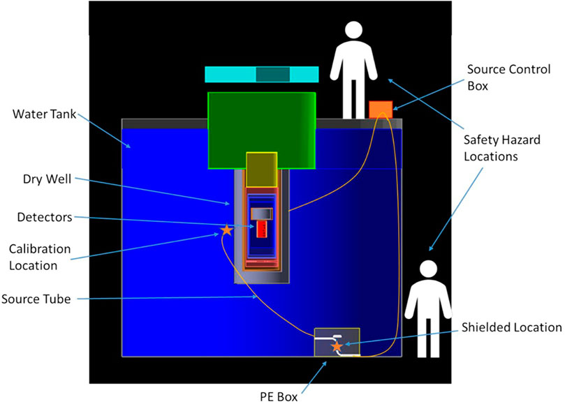
FIGURE 8. Schematic of the neutron calibration system from [19]. The source is moved by a stepper motor (orange box on the top right) through a tube that is installed inside the water shielding tank. The main locations of the source (inside the storage box, bottom right, and in the calibration position, next to the drywell) are indicated by orange stars. Monte Carlo simulations have been performed to asses the radiation exposure to personnel in the two indicated locations, demonstrating that any exposure would be negligible.
In a low-background experiment, the most critical part that needs to be protected from contamination is the payload itself. This means the installation or removal of the payload in CUTE must happen under especially clean conditions. While SNOLAB is operated as a class-2000 cleanroom, extended exposure of the SuperCDMS detectors to the lab air would still lead to an accumulation of dust, contributing to the detector background. An even more important contribution to the background would come from the high radon concentration of typically 130 Bq/m3 in the air at SNOLAB [17]. To protect the payload from exposure to dust and radon, a dedicated cleanroom was installed next to the CUTE water tank. This cleanroom is supplied with low-radon air, either compressed air brought into the lab from the surface with a typical Rn concentration of
A monorail crane is used to lift the cryostat from its operating position in the drywell to the cleanroom, where it is inserted through an opening in the roof. The centre section of the cleanroom roof has two sliding panels, each with a semi-circular cutout fitting tightly around the top part of the OVC can. When closed, the two-halves are locked together. When the cryostat is not in the cleanroom, a plastic lid closes the hole. When the cryostat is in the cleanroom, the various cans can be removed and installed using a hand-operated lifting platform in the centre of the cleanroom, directly underneath the cryostat. When the cryostat is open, the lower sections of the cryostat cans sit on that platform, nested within each other. Plastic collars are used to prevent the inner cans from sliding into the outer ones thus keeping the flanges easily accessible for remounting. Cover plates are available to be placed on top of the cans, providing a working surface directly underneath the cryostat to facilitate the payload installation. Dedicated sets of cryostat and detector tools are located permanently in the cleanroom for convenience. A small movable table is available inside the cleanroom for preparing the payload.
Full cleanroom gear (cleanroom suit, double gloves, booties, hair nets and face masks) must be worn when entering the cleanroom to ensure the best cleanliness standards. In the absence of an airlock, the air quality (particulates and Rn concentration) is compromised when the door is opened to enter the room. It is therefore important to let the air conditions settle (typical time for this process is ∼ 10–20 min) before exposing any critical components. Given the small size of the cleanroom, only two people are allowed to work inside at any given time. A third crew member is often located outside to aid with the work planning, coordination, and helping the crew inside with operating procedures and logging of activities. Communication is facilitated by means of a phone line, video conferencing technology and the fact that the walls of the cleanroom are transparent for instantaneous full visual feedback. Figure 9 shows the transfer of the cryostat into the cleanroom and a snapshot of the payload installation into CUTE.
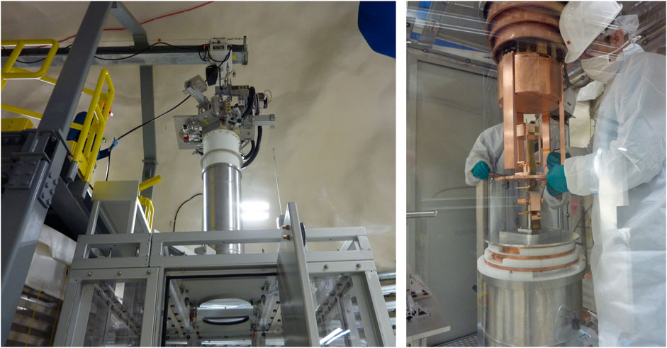
FIGURE 9. Left: The Dilution refrigerator is being moved from the drywell into the cleanroom by the monorail crane. The plastic disk in the ceiling of the cleanroom has been removed and the sliding panels are open, ready for the cryostat to be lowered. Right: A SuperCDMS tower with a single detector about to be mounted to the refrigerator is resting on a cover plate atop the nested cans.
The computer network for the facility is integrated into the SNOLAB network and is protected by a firewall. Access from the outside world is only possible by connecting to a virtual private network (VPN). This allows direct or indirect access to all network-enabled devices that are part of the facility. The present setup of the computer network makes use of two subnets: one is exclusive to the devices needed for the detector operation and readout and the other serves all other devices. A total of four computers are part of the network: one for the operation of the dilution refrigerator, one for all other slow-control activities, one for the data acquisition and one for data handling and transfer. In addition, CUTE has dedicated resources available at the SNOLAB surface facility, for data handling (receiving data from underground and sending them to partner institutions) and for some modest amount of data processing primarily for data quality control.
The facility has two uninteruptable power supplies (UPS). One unit (Eaton 93 E, 40 kW) can power the whole facility including the pumps and compressors of the dilution refrigerators for about 10 minutes. This is usually enough to bridge the facility until SNOLAB’s backup generator is able to restore power to the whole laboratory. In case the power restoration fails, a second smaller UPS (Eaton 9PX 6000) keeps the computing and network infrastructure of CUTE alive for about an hour. It comes with an extension module with eighteen 120 V power outlets, and allows for online oversight of the UPS performance and manual switching of individual outlets.
The slow-control system will be discussed in more detail in Section 9. The rest of this section is dedicated to a short description of the SuperCDMS-specific electronics and detector readout solutions.
As discussed in Section 2, the SuperCDMS detectors are mounted on a structure that includes the wiring between the three lowest temperature stages as well as key components of the first-stage amplifier electronics. For each detector installed, a cable with 100 individual conductors (wire loom with 50 twisted pairs) is attached to the tower-wiring and makes the connection to the 4 K stage of the cryostat; this cable is superconducting to minimize the conductive thermal load on the Still stage. From here another cable carries the signals to the room-temperature vacuum interface at the top of the cryostat. The vacuum feedthrough is achieved by a custom-designed printed circuit board (the Vacuum Interface Board, VIB) sandwiched between an ISO160 stainless steel flange. On the outside, custom-designed Detector Control and Readout Cards (DCRCs) attach directly to the VIB. These DCRCs hold the complete control and readout electronics including the signal digitization. They communicate directly with the data acquisition computer via an Ethernet connection and are powered by a 48-V Power-over-Ethernet (PoE) power supply. High voltage for the detector bias is provided by two ISEG HV modules (up to 500 V positive and negative respectively with eight outputs each) and brought to the boards through a dedicated connector on the VIB. The 24-port PoE as well as the HV power supply are identical to those used in SuperCDMS and will be available as backup for SuperCDMS if needed; otherwise they are part of the facility and available for other users of CUTE. Both devices can be addressed and controlled remotely.
A crucial aspect of the CUTE facility is its slow-control system which encompasses the monitoring and control for the cryogenic subsystems, the suspension system, the calibration source deployment systems and all other devices and sensors at the facility except the payload and its readout system. All of the available facility data are recorded and stored in a MySQL database on the slow-control computer.
The control and logging software for the dilution refrigerator and its auxiliary systems was developed and provided by the manufacturer of the dilution refrigerator, CryoConcept, and is installed on the fridge control PC. This software provides functionality to start and stop the pumps and compressors, open and close valves, control thermometry and heater settings, read out and log the thermometry and pressure gauges, and set parameters for automated tasks like “cool down” or “warm up”. While it provides the necessary functionality for normal fridge operations, it leaves room for improvements with regards to the monitoring and control of the compressor that drives the pulse tube cooler. In particular, the CryoConcept software cannot reset the compressor which is necessary after the occurrence of certain types of errors (e.g., when the cooling water temperature is out of range) or after a power outage. It also does not log the information from the compressor, such as water, oil and helium temperatures. Python scripts were developed to make those functionalities available so issues can be diagnosed easily and the system can be recovered remotely after faults.
The fridge control PC also runs a program monitoring the liquid nitrogen (LN) cold trap system: a 30-L LN Dewar containing the trap sits on a scale which is continually read out by a Python script. The weight can then be translated into the amount of LN in the Dewar. The setup also includes a LN-refill system (Norhof LN2 microdosing system) with a separate 100-L low-pressure LN Dewar. A heater inside this Dewar builds up pressure for transferring LN to the cold-trap Dewar when needed.
The Peltier cooler for the turbo pump is operated by a hardware controller to maintain its temperature. A Python script was developed to interface with the controller to start and stop the cooler, set the temperature and log the temperature and the output power of the controller.
The suspension system and the calibration systems are both operated through AVR microcontrollers. To communicate with the AVRs, a server written in Node. JS is running on the slow-control computer. Each AVR microcontroller is flashed with a C code that handles the driving of the stepper motors, the I/O of the digital pins, the measurements of the ADCs, and the USB communications. The actual logic used by the suspension and calibration systems is implemented in the Node server, and the microcontroller code only handles the low level hardware control. This provides an additional layer of flexibility by being able to easily add new functionality to the system without having to reprogram the AVR. The Node server creates the USB connection to the microcontrollers, and allows clients to connect to and communicate with the server via a websocket interface.
The logic for the suspension system control software is based on continually reading out the optical sensors via an ADAM-6017 module. A nominal position for the suspension system is set by the user. While the original design anticipated this to be in the centre of the 2 mm-vertical range of the suspension system (that is at 1.0 mm), it can be set to any value between 0 and 2 mm. If a sensor reading deviates from the nominal position by more than a predefined amount, the respective stepper motor is driven in the appropriate direction to adjust the damper position and thus bring it back into range. The tolerance is presently set to 0.04 mm which offers a good compromise between stability of operation and adjustment frequency. A safety feature stops the automation if an extended adjustment by the stepper motor does not lead to a significant change in the measured position of the suspension system. In addition to the automated position control, each stepper motor can be individually controlled by the user to move up or down with an adjustable speed.
The compression of the dampers as determined by the Hall effect sensor together with the optical sensor is converted to an equivalent mass that should be added to or removed from each damper to bring it to its nominal operating point. This is mostly relevant when a new payload with a significantly different mass has been installed. Weights can be added to or removed from the suspension frame to bring the compression into the desired range.
The Node server also controls the stepper motor that deploys and retracts the gamma calibration source. Via the web interface, users can send the sources to specific positions. The feedback sensors (see Section 6) are used to confirm that the source is moving as intended (optical sensor) or to confirm it is in the housing (home sensor). This is useful after a power outage (in which case the information on the present position can get lost) or as a quick feedback if the source is not moving as intended.
The monitoring and control for the various subsystems is conveniently brought together on a single webpage. The status of the cryogenic systems, suspension system, the Ba calibration system and the Peltier cooler are prominently featured, and key parameters from across the facility are displayed in a ribbon along the top of the page. The suspension system, the calibration system and the Peltier cooler can also be controlled through this webpage. In addition, it includes a feature for plotting and downloading data from the database for easy monitoring of the performance of the facility over time. The slow-control webpage is accessible for all users of the facility while the operation of the dilution refrigerator is limited to a small number of experts; hence, most of the functionality of the fridge control software was deliberately not included in this webpage. Figure 10 shows a screen shot of this webpage.
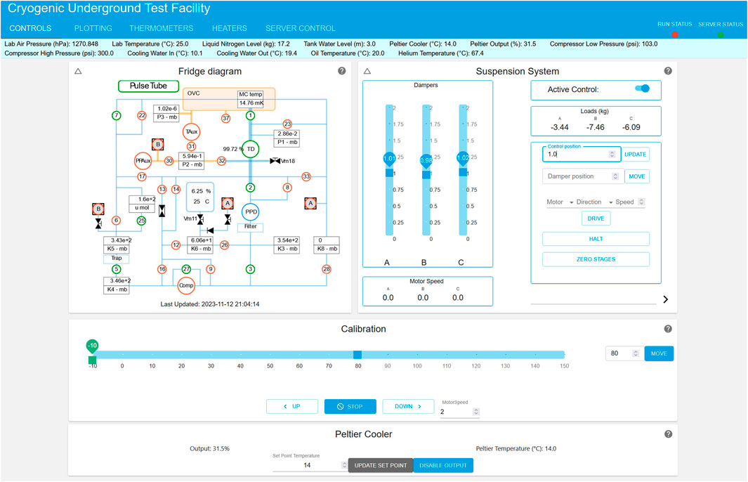
FIGURE 10. Screen-shot of the main slow-control webpage. In the top half are the fridge monitoring panel (left) and the panel for the monitoring and control of the suspension system (right). Active elements in the fridge monitoring panel (pumps, valves) are green, while inactive ones are red. The gamma calibration source is controlled through the first horizontal panel in the lower half; it indicates that the source is located inside the shielding box (”−10 cm”; 0 is just outside the lead shielding and level with the top rim of the lower part of the drywell). The lower horizontal bar controls the Peltier cooler. The cyan-colored banner above the panels shows various facility parameters (including lab air temperature and pressure). The blue top-banner allows the user to choose the alternate tabs for plotting and data downloading, control of the fridge thermometers and heaters, and an interface to easily check the status of (and if necessary restart) the servers for the suspension and calibration systems, the Peltier cooler and the compressor monitoring.
Accessing SNOLAB comes with considerable extra effort compared to most other work places, due to its location 2 km underground in an active mine and the cleanliness requirements in the lab. In addition, there is no regular access during weekends and holidays, including extended no-access periods during the winter holidays and typically for several weeks during the summer for maintenance work by the mining company. Therefore it is important to be able to remotely monitor and control various aspects of the facility and experiment. Significant effort was made to ensure that CUTE can operate without operators present at the lab for an extended period.
The fridge control software operates on a remotely accessible PC and includes all functionality that is required for operating the dilution refrigerator. With the above mentioned custom additions, this also includes a restart after a loss of power. The nitrogen refill system can also be operated remotely; thus, the dilution refrigerator can operate for up to about 2 months without personnel underground. As discussed in Section 9, all relevant systems are remotely controllable and all facility data are accessible through the database. In addition to the aforementioned systems, a remote controlled power distribution unit with five outlets is located at the deck, for connecting and switching auxiliary devices on and off. Finally, the PoE and the HV power supplies are fully remotely controllable.
If all services are available, the period for complete remote operation is limited by the LN supply. Power interruptions can be bridged for about 10 minutes (see Section 8). If the facility loses power, it can be recovered remotely, provided the other systems are operating. However, depending on the length of the outage the cryostat may have warmed up significantly in which case the recovery would take an extended period and may consume significantly more LN than in steady state operations. Compressed air is required for switching the valves of the dilution refrigerator. As a backup in case of a loss of compressed air, there is presently a small buffer tank. In steady state operation when no valves are changing state, this lasts for several hours, but runs quickly out when valves are operated. The backup is sufficient to collect and secure the helium mixture in case an extended outage is expected. For cooling water, CUTE is connected to the low-pressure cooling water loop installed for SuperCDMS. This system presently has no backup in case of failure (either of the low-pressure loop itself, or the primary high-pressure cooling loop operated by SNOLAB). In case the cooling water fails, the compressor for the pulse tube cooler will stop operating after roughly a minute or two. SuperCDMS is exploring options to ensure the long-term stability of the system.
As discussed earlier, the original motivation for building this facility was the testing of the new SuperCDMS detectors under low-background conditions. However, CUTE provides an ideal environment for testing and operating a wide range of cryogenic devices that are known or suspected to be affected by radiation and vibrations. Prime examples are cryogenic detectors for rare event searches such as the direct detection of dark matter, neutrinoless double beta-decay or other rare nuclear decays (see, e.g., [24–26]) for the reasons discussed in Sec. 1. Depending on the expected event rate, the size and background of the CUTE facility may also be sufficient to carry out actual rare event searches. Even though the facility background of CUTE is noticeably higher than what is expected for the SuperCDMS experiment, operating one of the SuperCDMS HV detector towers for a few months could push the sensitivity of SuperCDMS a good fraction of the way towards the final goal of SuperCDMS SNOLAB.
The special environment provided by CUTE may also benefit cryogenic devices being developed in the fields of quantum information and quantum sensing. A leading platform to form the basis of a practical quantum computer are superconducting quantum bits (qubits), due to their modular design and the fact that they can be easily fabricated using techniques developed by the semiconductor industry. It has been shown recently that ionizing radiation could generate excess quasiparticles in superconducting qubits, thereby degrading their performance in a way that would not be easily handled by error correcting codes [27, 28]. Operating such devices in a low-background environment would reduce the error rate due to particle interactions significantly and open the door to studying (and potentially resolving) more fundamental limitations.
The low radiation environment provided by CUTE is not only of interest for testing cryogenic devices in the near absence of radiation, but also allows for dedicated tests of their response to radiation in a controlled way. For particle detectors this is important for calibration measurements as discussed in Section 6, but is, for example, also relevant to understanding and quantifying the impact of ionizing radiation on the coherence time and correlated error rates of superconducting qubits [27, 28].
While quantum computing has the potential to revolutionize a variety of fields, the most mature area of quantum technology is currently that of quantum sensors, which also have the most promise for applications in the near future. Mechanical force sensors based on levitated superconductors currently find use in industry as gravimeters [29], and there is growing interest to improve the sensitivity of this technology by coupling the levitated superconductor to a superconducting qubit and demonstrating cooling to the quantum mechanical ground state [30]. One of the main technical limitations of this technology is mechanical vibrations, which can be mitigated by operating such a device in the low-vibration environment as provided by the CUTE facility. Moreover, if this technology reaches its projected sensitivity it could become difficult to operate in a regular laboratory due to minute environmental gravitational disturbances such as could be induced, e.g., by vehicles driving near the laboratory. A controlled remote environment such as provided by CUTE would significantly reduce the level of such disturbances.
Other devices that could benefit from the low-vibration environment provided by CUTE are small-scale gravitational wave detectors, sensitive to frequencies above 1 kHz [31]. Such devices could be sensitive to millisecond pulsars and exotic signatures produced by decays or annihilations of axions [31]. If this technology is to reach its full potential, an environment with low-vibrations, including low levels of seismic vibrations, would be essential.
After the end of detector testing for SuperCDMS, CUTE will be available to other interested projects. Time will be allocated based on scientific and technological merits of submitted proposals2, and the CUTE team will work with users on the installation plan and help with all facility interfaces. Some basic equipment will be available to the users, and the aim is to constantly improve the facility to provide more support. For example, a microwave setup consisting of cryogenic coaxial cables, attenuators, filters, and amplifiers is planned to be installed in the near future for a specific experiment, but will stay at CUTE and be available afterwards for other users.
CUTE is an underground facility at SNOLAB, built for the purpose of testing cryogenic detectors and other devices in a low-background and low-vibration environment. The underground location together with a composite shielding of water, low-activity lead and polyethylene drastically reduce the flux of cosmogenic and radiogenic radiation. A layer of magnetic shielding reduces the Earth’s magnetic field by about a factor of fifty at the location of the payload, and the mechanical decoupling of the cryostat from the upper part of the dilution refrigerator (which includes the pulse tube cooler cold head) together with the cryostat’s suspension system significantly reduces the level of vibrations which otherwise might negatively impact the performance of the devices being operated in CUTE. The CUTE facility currently includes a133Ba source delivery system that can be used for detector calibrations and other studies of the impact of gamma radiation on devices, and a252Cf neutron source delivery system is planned to be installed and commissioned soon; certain other sources may be made available upon request. Overall, the CUTE facility provides an excellent environment for cryogenic experiments that require low levels of radiation. While the primary motivation for the facility was to test SuperCDMS SNOLAB detectors in an environment with a similar background level as the main experiment, once the testing of SuperCDMS detectors in CUTE is complete, the facility will be available for other experiments on a proposal basis.
The raw data supporting the conclusions of this article will be made available by the authors, without undue reservation.
Written informed consent was obtained from the individual(s) for the publication of any potentially identifiable images or data included in this article.
PC: Conceptualization, Formal Analysis, Investigation, Methodology, Project administration, Writing–review and editing, Validation, Visualization. JC: Formal Analysis, Investigation, Methodology, Writing–review and editing, Validation, Visualization. SC: Methodology, Writing–review and editing. KD: Methodology, Project administration, Writing–review and editing, Visualization. EF: Formal Analysis, Investigation, Writing–review and editing, Validation, Visualization, Supervision. GG: Conceptualization, Formal Analysis, Funding acquisition, Investigation, Methodology, Project administration, Supervision, Writing–review and editing, Validation, Visualization. RG: Conceptualization, Formal Analysis, Investigation, Methodology, Software, Supervision, Writing–original draft, Writing–review and editing, Validation, Visualization. MG: Formal Analysis, Investigation, Methodology, Writing–original draft, Writing–review and editing, Validation, Visualization. JH: Funding acquisition, Investigation, Methodology, Writing–review and editing, Resources. ZH: Funding acquisition, Investigation, Project administration, Writing–review and editing, Supervision, Visualization. AK: Investigation, Project administration, Writing–review and editing, Supervision, Visualization. AM: Investigation, Writing–review and editing, Data curation, Formal Analysis, Validation, Methodology. SN: Investigation, Methodology, Project administration, Writing–review and editing, Supervision. PP: Methodology, Writing–review and editing. WR: Conceptualization, Funding acquisition, Investigation, Methodology, Project administration, Supervision, Writing–original draft, Writing–review and editing, Formal Analysis, Validation, Visualization. SS: Formal Analysis, Investigation, Project administration, Validation, Writing–original draft, Writing–review and editing, Software, Supervision, Visualization. RU: Investigation, Methodology, Writing–original draft, Writing–review and editing, Data curation, Formal Analysis, Software, Validation, Visualization.
This research was financially supported by the Canada Excellence Research Chair program (grant held by Dr. Gerbier), Queen’s University (Special Research Grant held by Dr. Rau), the Natural Sciences and Engineering Research Council of Canada (SuperCDMS project grant SAPPJ-2017-00030, and grant SAPPJ-2021-00024 held by Dr. Hall), the Canada First Research Excellence Fund through the Arthur B. McDonald Canadian Astroparticle Physics Research Institute (grant CFREF-2015-00009), and the University of Toronto (Special Research Grant held by Dr. Hong). In-kind contribution were provided by SNOLAB, with SNOLAB operations being funded by the Canada Foundation for Innovation and the Province of Ontario, and supported by Vale Canada.
The construction of CUTE was made possible through the provision of funds by Dr. Gilles Gerbier (Queen’s University) from his Canada Excellence Research Chair grant and generous support from SNOLAB. Additional funds were provided by Queen’s University through a Special Research Grant held by Dr. Wolfgang Rau. The operation and a variety of upgrades were funded largely by the Natural Sciences and Engineering Research Council of Canada (SuperCDMS project grant and an individual grant held by Dr. Jeter Hall), the Arthur B. McDonald Canadian Astroparticle Physics Research Institute, through support for research groups at TRIUMF, the University of Toronto, and the University of British Columbia as well as through engineering and technical support, and by the University of Toronto through a Special Research Grant held by Dr. Ziqing Hong. A contribution to the 3He-contingent was made by Dr. Matt Pyle (University of California, Berkeley). During the construction, the technical and engineering support at Queen’s University was invaluable; we thank in particular Chuck Hearnes, Robert Gagnon and Phil Harvey for their contributions. We would like to thank SNOLAB and its staff for support through underground space, logistical and technical services. SNOLAB operations are supported by the Canada Foundation for Innovation and the Province of Ontario, with underground access provided by Vale Canada Limited at the Creighton mine site. Particular thanks for on-site support go to Jasmine Gauthier and José Marco Olivares. A lot of students contributed during their internship at SNOLAB to the Monte Carlo simulations and CUTE detector payload changes; we especially thank Melissa Baiocchi, Scarlett Gauthier, Sabrina Cheng, Jordan Ducatel and Alexander Pleava for their strong commitment. We also thank the group of students from the British Columbia Institute of Technology, Sean Green, Karel Chanivecky Garcia, Gurden Singh Angi and Johnathon Gordon Scott who helped develop the slow-control webpage, and all other undergraduate summer and Co-op students who were involved in the project over the years. Last but not least we thank the SuperCDMS Collaboration: for validating the performance of the facility, the operation of SuperCDMS devices was invaluable. We thank SuperCDMS for providing these devices as well as personnel to operate them and assess their performance.
The authors declare that the research was conducted in the absence of any commercial or financial relationships that could be construed as a potential conflict of interest.
The author declared that they were an editorial board member of Frontiers, at the time of submission. This had no impact on the peer review process and the final decision.
All claims expressed in this article are solely those of the authors and do not necessarily represent those of their affiliated organizations, or those of the publisher, the editors and the reviewers. Any product that may be evaluated in this article, or claim that may be made by its manufacturer, is not guaranteed or endorsed by the publisher.
1“Faible Activite” (FA) lead with about 40 Bq/kg, and “Tres Faible Activite” (TFA) lead with about 6 Bq/kg of 210Pb, from the Fonderie de Gentilly, France.
2Send proposals via e-mail to cute_cHJvcG9zYWxzQHNub2xhYi5jYQ== or contact SNOLAB management.
1. Petricca F, Angloher G, Bauer P, Bento A, Bucci C, Canonica L, et al. First results on low-mass dark matter from the CRESST-III experiment. J Phys Conf Ser (2020) 1342:012076. doi:10.1088/1742-6596/1342/1/012076
2. Mantegazzini F, Kovac N, Enss C, Fleischmann A, Griedel M, Gastaldo L. Development and characterisation of high-resolution microcalorimeter detectors for the ECHo-100k experiment. Nucl Instrum Methods A (2023) 1055:168564. doi:10.1016/j.nima.2023.168564
3. Alkhatib I, Amaral D, Aralis T, Aramaki T, Arnquist I, Ataee Langroudy I, et al. Light dark matter search with a high-resolution athermal phonon detector operated above ground. Phys Rev Lett (2021) 127:061801. doi:10.1103/physrevlett.127.061801
4. Rothe J, Angloher G, Ardellier-Desages F, Bento A, Canonica L, Erhart A, et al. NUCLEUS: exploring coherent neutrino-nucleus scattering with cryogenic detectors. J Low Temp Phys (2020) 199:433–40. doi:10.1007/s10909-019-02283-7
5. Agnese R, Anderson A, Aralis T, Aramaki T, Arnquist I, Baker W, et al. Low-mass dark matter search with CDMSlite. Phs Rev D (2018) 97:022002. doi:10.1103/physrevd.97.022002
6. Marnieros S, Armengaud E, Arnaud Q, Augier C, Benoît A, Bergé L, et al. High impedance TES bolometers for EDELWEISS. J Low Temp Phys (2023) 211:214–9. doi:10.1007/s10909-022-02899-2
7. Amaral DW, Aralis T, Aramaki T, Arnquist I, Azadbakht E, Banik S, et al. Constraints on low-mass, relic dark matter candidates from a surface-operated SuperCDMS single-charge sensitive detector. Phys Rev D (2020) 102:091101. doi:10.1103/physrevd.102.091101
8. Agnese R, Aralis T, Aramaki T, Arnquist I, Azadbakht E, Baker W, et al. Production rate measurement of tritium and other cosmogenic isotopes in germanium with CDMSlite. Astropart Phys (2019) 104(1):1–12. doi:10.1016/j.astropartphys.2018.08.006
9. Albakry MF A strategy for low-mass dark matter searches with cryogenic detectors in the SuperCDMS SNOLAB facility (2022). Available at: https://arxiv.org/abs/2203.08463.
10. Camus P, Cazes A, Dastgheibi-Fard A, Dering K, Gerbier G, Rau W, et al. CUTE: a low background facility for testing cryogenic dark matter detectors. J Low Temp Phys (2018) 193:813–8. doi:10.1007/s10909-018-2014-0
11. Rau W, Gerbier G, Camus P, Dering K, Cazes A, Scorza S, et al. CUTE - a cryogenic underground test facility at snolab. J Phys Conf Ser (2020) 1342:012128. doi:10.1088/1742-6596/1342/1/012128
12. Agnese R, Anderson A, Aramaki T, Arnquist I, Baker W, Barker D, et al. Projected sensitivity of the SuperCDMS SNOLAB experiment. Phys Rev D (2017) 95(8):082002. doi:10.1103/physrevd.95.082002
13. Smith N The SNOLAB deep underground facility. Eur Phys J Plus (2012) 127:108. doi:10.1140/epjp/i2012-12108-9
14. Neganov BS, Trofimov VN. Colorimetric method measuring ionizing radiation. Otkryt Izobret (1985) 146:215.
15. Luke PN Voltage assisted calorimetric ionization detector. J Appl Phys (1988) 64:6858–60. doi:10.1063/1.341976
16. Mei D-M, Hime A. Muon-induced background study for underground laboratories. Phys Rev D (2006) 73:053004. doi:10.1103/physrevd.73.053004
17. SNOLAB. SNOLAB user’s handbook revision 2 (2022). Available at: http://snolab2008.snolab.ca/snolab_users_handbook_rev02.pdf.
18. Germond R Techniques and challenges in low-mass dark matter searches. PhD Thesis. Kingston, Canada: Queen’s University (2023).
19. Corbett J. Neutron calibration system for the cryogenic underground TEst facility (CUTE). MSc Thesis. Kingston, Canada: Queen’s University (2021).
20. Liu S. The limiting background in a detector testing facility for SuperCDMS at SNOLAB. MSc Thesis. Kingston, Canada: Queen’s University (2011).
21. Agostinelli S, Allison J, Amako K, Apostolakis J, Araujo H, Arce P, et al. Geant4—a simulation toolkit. Nucl Instrum Methods A (2003) 506(3):250–303. doi:10.1016/s0168-9002(03)01368-8
22. Loer B. Background explorer (2023). Available at: https://github.com/bloer/bgexplorer.
23. Nuvap. company (2022). Available at: https://www.nuvap.com/en/.
24. Poda D. Scintillation in low-temperature particle detectors. Physics (2021) 3(3):473–535. doi:10.3390/physics3030032
25. Alduino C, Alessandria F, Alfonso K, Andreotti E, Arnaboldi C, Avignone FT, et al. First results from cuore: a search for lepton number violation via 0νββ decay of 130te. Phys Rev Lett (2018) 120(13):132501. doi:10.1103/PhysRevLett.120.132501
26. Armatol A, Broerman B, Dumoulin L, Giuliani A, Khalife H, Laubenstein M, et al. ZnO-based scintillating bolometers: new prospects to study double beta decay of 64Zn. J Inst (2023) 18:P06026. doi:10.1088/1748-0221/18/06/p06026
27. Antti P, Karamlou AH, Orrell JL, Dogra AS, Loer B, Vasconcelos F, et al. Impact of ionizing radiation on superconducting qubit coherence. Nature (2020) 584(7822):551–6. doi:10.1038/s41586-020-2619-8
28. Cardani L, Colantoni I, Cruciani A, De Dominicis F, D’Imperio G, Laubenstein M, et al. Disentangling the sources of ionizing radiation in superconducting qubits. Eur Phys J C (2023) 83(1):94. doi:10.1140/epjc/s10052-023-11199-2
29. Goodkind JM The superconducting gravimeter. Rev Sci Inst (1999) 70(11):4131–52. doi:10.1063/1.1150092
30. Romero-Isart O, Clemente L, Navau C, Sanchez A, Cirac JI. Quantum magnetomechanics with levitating superconducting microspheres. Phys Rev Lett (2012) 109:147205. doi:10.1103/physrevlett.109.147205
Keywords: cryogenic, low radiation background, underground science, SNOLAB, dark matter, rare event searches, CUTE
Citation: Camus P, Corbett J, Crawford S, Dering K, Fascione E, Gerbier G, Germond R, Ghaith M, Hall J, Hong Z, Kubik A, Mayer A, Nagorny S, Pakarha P, Rau W, Scorza S and Underwood R (2024) CUTE: A Cryogenic Underground TEst facility at SNOLAB. Front. Phys. 11:1319879. doi: 10.3389/fphy.2023.1319879
Received: 11 October 2023; Accepted: 04 December 2023;
Published: 11 January 2024.
Edited by:
Osvaldo Civitarese, National University of La Plata, ArgentinaReviewed by:
Olga Gileva, Institute for Basic Science (IBS), Republic of KoreaCopyright © 2024 Camus, Corbett, Crawford, Dering, Fascione, Gerbier, Germond, Ghaith, Hall, Hong, Kubik, Mayer, Nagorny, Pakarha, Rau, Scorza and Underwood. This is an open-access article distributed under the terms of the Creative Commons Attribution License (CC BY). The use, distribution or reproduction in other forums is permitted, provided the original author(s) and the copyright owner(s) are credited and that the original publication in this journal is cited, in accordance with accepted academic practice. No use, distribution or reproduction is permitted which does not comply with these terms.
*Correspondence: Wolfgang Rau, d3JhdUB0cml1bWYuY2E=
†Present addresses: Philippe Camus, Institut Néel, CNRS, Grenoble, France
Richard Germond, Institute for Quantum Computing, University of Waterloo, Waterloo, ON, Canada
Muad Ghaith, Zayed University, Dubai, United Arab Emirates
Adam Mayer, Lancaster University, Lancaster, United Kingdom
Silvia Scorza, Univ. Grenoble Alpes, CNRS, Grenoble INP*, LPSC-IN2P3, Grenoble, France
Disclaimer: All claims expressed in this article are solely those of the authors and do not necessarily represent those of their affiliated organizations, or those of the publisher, the editors and the reviewers. Any product that may be evaluated in this article or claim that may be made by its manufacturer is not guaranteed or endorsed by the publisher.
Research integrity at Frontiers
Learn more about the work of our research integrity team to safeguard the quality of each article we publish.