- Department of Mechanical Engineering, University of Michigan, Ann-Arbor, MI, United States
We present a reconfigurable elastic metasurface design composed of an array of zigzag-folded sheets with parallel corrugations to control the wavefront of the refracted A0 Lamb mode wave. The performance of this origami-inspired metasurface can be tuned by tailoring the thickness and folding angles of the sheets. Zigzag-folded sheets exhibit dynamic properties depending on their thicknesses and folding angles, yielding different phase profiles required for wavefront control via the metasurface. The transmission characteristics and phase modulation capability of the metasurface units are studied through numerical models and utilized to inform the metasurface design reconfiguring for different wave functions, such as wave focusing and deflecting at different frequencies. The design frameworks and the applicability of the reconfigurable metasurface are validated using a full-scale experimental setup. Overall, the proposed metasurface can accomplish distinct wavefront controls at adjustable geometrical parameters, developing new potentials for designing intelligent systems adaptable to different environments.
1 Introduction
Controlling and manipulating acoustic/elastic waves via phase-modulated metasurfaces has gained increased research interest over the past decade. A metasurface consists of an array of subwavelength-scaled phase modulators that introduce abrupt phase shifts in the wave propagation path and tailor the wavefront based on generalized Snell’s law (GSL) [1]. Hence, it can provide a compact and lightweight approach to controlling acoustic/elastic waves, which makes them ideal for diverse applications such as lensing [2, 3], energy harvesting systems [4, 5], imaging [6], holography [7, 8] and cloaking [9, 10].
In general, anomalous wave control is achieved by tailoring the phase gradients via the structural design of the metasurface unit cells [5, 11–18]. Examples of these designs include torus-like tapers [14], perforated substrates [16], rectangular zigzag structures [15, 19–21], pillar attachments [6, 18, 22], and slender beams [5, 23], which have demonstrated capability in elastic wavefront shaping, such as wave focusing and wave deflection. However, once fabricated, most existing metasurface designs have a fixed geometric configuration, restricting their effectiveness to specific spatial dimensions for generating the desired wave functions. To overcome this limitation, researchers have utilized different techniques including piezoelectric shunts [24–29], screws-thread bars resonators [30, 31] and magnetically tuned sub-units [32], to enable a tunable or reconfigurable design of the metasurface.
Notably, recent advancements have integrated origami art into the architected material designs due to its inherent merits of being deployable and reconfigurable. As a basic origami pattern, origami-inspired zigzag sheets/rods have been widely used in civil engineering and aerospace applications due to high reconfigurability, the ease of design, and the potential to maintain lateral dimension at different deployed states, i.e., zero-Poisson’s ratio [33–37]. Extensive research has demonstrated that zigzag corrugated structures can achieve extraordinary mechanical properties, such as high stiffness [38, 39], significant strength to weight ratio [40], and low sensitivity to buckling [41]. Aside from peculiar mechanical properties, researchers have also leveraged the dynamic properties of origami-inspired zigzag structures to achieve unconventional control over wave propagation. For instance, Han [42] proposed a zigzag foldable polyline rod to achieve a tunable band gap by folding the structure. Nanda and Karami [43] investigated the band structure characteristics of the origami-inspired zigzag folded sheets and found modes coupling phenomenon in the folded state. Later, Xu [44] further studied the mode coupling phenomenon in the zigzag folded beams under different material constants and geometrical sizes and proposed an elastic metasurface to achieve tunable reflected wavefront control by individually tuning each zigzag beam [45]. While promising, the current studies on origami-inspired wave control focus on analyzing their band structures and vibration isolation capability. Yet, the phase modulation and wavefront control capability of these structures are less explored. In addition, existing origami-inspired zigzag metasurfaces require individual adjustment of the unit cells to achieve different wavefront control while achieving reconfigurable performance through simple one-step adjustment, e.g., folding the entire metasurface, is less explored.
To advance the state of the art, this study proposes an origami-inspired metasurface to control the wavefront of the refracted A0 Lamb mode wave, which exhibits flexural vibration in the plate [46, 47]. We exploit the folding mechanism and design a metasurface composed of an array of zigzag-based folded sheets with parallel corrugations to control the wavefront of the refracted A0 Lamb mode wave. The phase velocity of the metasurface units can be tailored by changing the thickness of the facets and folding angles, resulting in different phase gradients towards desired wavefronts in the refracted region. To this end, we design reconfigurable metasurfaces and achieve distinct wave control at different frequencies and folding angles. Both numerical and experimental methods are adopted to test the performance of the proposed metasurface, proving that the performance of the origami-inspired metasurface can be adjusted by only tuning the folding angle of the entire structure.
The outline of this paper is as follows: Section 2 introduces the conceptual design of the metasurface. In Section 3, the wave propagation characteristics of metasurface units under different folding angles are explored. Based on the phase modulation performance, we design wave-focusing and wave-deflecting metasurfaces to achieve reconfigurable wavefront control depending on the folding angles in Section 4. Furthermore, the focusing metasurface performance under different folding angles and operating frequencies are experimentally validated in Section 5. Section 6 summarizes the key points in this study.
2 The design concept of the metasurface
We investigate wavefront shaping of low-frequency elastic waves via a reconfigurable metasurface inspired by origami folding. The proposed metasurface consists of 41 zigzag-folded sheets separated with a 2 mm gap and periodically placed in the middle of two acrylic plates, which are used to control transmitted A0 mode Lamb wave as shown in Figure 1A. The substrate acrylic beam has a thickness of hs = 2 mm, a width of
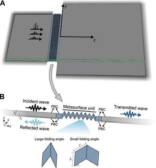
FIGURE 1. Schematic of (A) origami-inspired zigzag-folded metasurface placed in the middle of two plates and (B) the metasurface unit. The perfectly matched layers (PMLs) are implemented to simulate the infinite domains. The inset in (B) shows the unit cells with different folding angles.
3 Analysis of the folded metasurface unit
To reveal the wave control mechanism of the zigzag-folded metasurface, we calculate the dispersion relations of a single unit cell through numerical simulations in COMSOL Multiphysics. Then, the transmission ratios and phase shifts of the metasurface units are resolved by considering an infinitely long acrylic waveguide as shown in Figure 1B. In this study, the metasurface units are modeled using shell elements with structured mesh and assigned thickness, while 3D plate models with tetrahedral mesh are established to capture the dynamic response of the substrate. A high quality mesh was ensured by using quadratic element and setting the minimum mesh size to λ/90. The Solid-Thin Structure Connection is applied at the interfaces of the substrate beam and metasurface unit. The continuous periodic boundary condition (PBC) is applied at lateral sides of the one-dimensional waveguide, and the perfectly matched layers (PMLs) are implemented at the ends to avoid the boundary reflections as shown in Figure 1.
3.1 Dispersion relations
Dispersion relations carry essential information on the wave propagation characteristics by expressing the wavenumber as a function of frequency. As a first step, we evaluate the dispersion relations of the unit cell with two facets and a specific thickness of t = 2 mm under different folding angles, using COMSOL Multiphysics. The Floquet-periodic boundary condition (Floquet BC) is applied on the edges of the unit cell, as shown in the inset of Figure 2A [48–50]. The dispersion curve of the first branch flexural-dominated vibrating mode of the unit cell is shown in Figures 2A, B, demonstrating a slight change for small folding angles (θ < 45°) and an increasing cut-off frequency with larger folding angles (α > 45°). At a given frequency, by exploiting the variations in phase velocity, the metasurface unit can introduce different phase gradients into the propagating A0 mode wave. Furthermore, the dispersion relations under three specific folding angles of α = 0°, 30°, and 70° are shown in Figure 2C. By changing the folding angle of the metasurface, a new band gap opens, forbidding the wave propagating under folded states.
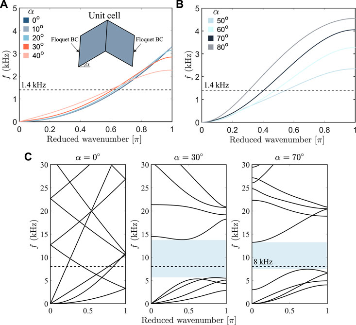
FIGURE 2. Dispersion curves of the flexural-dominated vibrating mode of the unit cell with (A) small folding angles (α <45°) and (B) large folding angles (α >45°). (C) The band structures of the unit cell with a facets’ thickness of 2 mm under different folding angles. The band gap of the configuration of α =30° and 70° are marked by the shaded regions.
3.2 Wave propagation characteristics of metasurface unit
We investigate the wave propagation characteristics of the one-dimensional waveguide assembling eight unit modules between two acrylic beams, as shown in Figure 1B. The one-dimensional waveguide model is established in COMSOL Multiphysics with the PMLs are implemented at both ends to avoid reflection from boundaries. The harmonic flexural boundary load is applied to generate the incident A0 mode. In order to capture the potential mode conversion phenomenon that exists in this wave scattering problem, the out-of-plane (w) and longitudinal (u) displacements are given in Eq. (1) under incident A0 mode.
where uinc(tran) and winc(tran) are the longitudinal and out-of-plane displacements in the incident (transmitted) domain, respectively. The superscript I, R, and T represent incident, reflected, and transmitted waves, respectively. The subscripts A0 and S0 indicate the vibration patterns. p and e represent the propagating and evanescent components, respectively. Subsequently, the wave amplitudes can be obtained by fitting the wavefield results from numerical simulations to the vibrating patterns in Eq. 1. Then the transmission characteristics of A0 mode are obtained by dividing the propagating transmitted wave amplitude
where
With this method, we investigate the wave transmission characteristics, i.e., the transmission ratio and phase shift, of the metasurface unit under an incident flexural wave at 1.4 kHz. By sweeping facets’ thicknesses and folding angles, we explore the transmission characteristics under different geometrical parameters (i.e., thickness and folding angle), as shown in Figures 3A, B. When the metasurface is deployed with a small folding angle, i.e., (α < 30°), most incident wave energy passes through the metasurface unit while introducing similar phase profiles in the transmitted A0 mode. For a folding angle larger than 30°, increasing the folding angle results in a smaller phase shift under the same facets’ thickness, as depicted in Figure 3B.
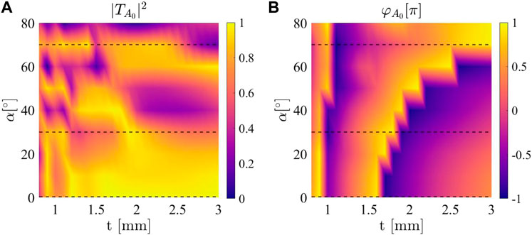
FIGURE 3. Transmission characteristics of the metasurface unit under 1.4 kHz flexural incident wave. (A) Transmitted ratios and (B) Phase shifts of transmitted A0 mode under different folding angles and facets’ thicknesses. The dashed lines show the folding angles of α =0°, 30° and 70°.
To demonstrate the variation of phase shift for different folding angles, we evaluate three examples, i.e., α = 0°, 30°, and 70°, as highlighted by the dashed lines in Figure 3. Accordingly, the transmitted ratios and phase shifts of A0 mode under different facets’ thicknesses and folding angles are plotted in Figures 4A, B, respectively. Under different folding angles, the introduced phase shifts can cover the entire 2π phase range while maintaining a relatively high transmission ratio within the region of interest. In addition, the phase shift results show that the same thickness introduces a similar phase shift under small folding angles, i.e., α = 0° and 30°. When the metasurface unit is folded to 70°, it introduces minor phase shifts. This feature can be used to design reconfigurable metasurfaces to achieve tunable performance at different folding angles, unlocking the potential for creating adaptable systems that can fit in different geometric lengths. We further analyzed the mechanism for the phase-shift change in the transmitted component by examining the natural frequency of the first bending mode of the metasurface unit, f1. Figure 4C demonstrates the variation of f1 under different folding angles and clamped-clamped boundary conditions. It is observed that increasing the folding angle results in a larger natural frequency f1, indicating a higher bending stiffness since the mass of the metasurface unit remains the same. In addition, for a homogeneous beam under clamped-clamped boundary conditions, the first natural frequency of the bending mode is

FIGURE 4. Effect of facets’ thickness on (A) transmitted ratios and (B) phase shifts of the A0 mode under different folding angles and 1.4 kHz incident flexural wave. The phase shifts are plotted with respect to t =1 mm. (C) Natural frequency of the first bending mode of the metasurface unit under different folding angles and clamped-clamped boundaries.
4 Wavefront shaping and metasurface design
We further investigate wavefront shaping of low-frequency A0 mode waves via the zigzag-folded metasurface composed of 41 metasurface units separated with a 2 mm gap. The incident A0 mode wave is generated by applying a harmonic flexural boundary load, and the model is surrounded by the PMLs to simulate the infinite substrate elastic domain, as depicted in Figure 1A. In this section, our primary goal is to demonstrate the adaptive wavefront control capability of the proposed zigzag metasurface under different folding angles and operating freqeuncies.
4.1 Case I: Wave focusing
The folded metasurface concept is first used to enable reconfigurable focusing phenomena depending on operating frequency and folding angle. To achieve wave focusing at a focal distance fx in the transmitted region, the phase gradient should be satisfied a hyperbolic form [14, 29] given as:
where φ(y) represents the required phase value at location y along the metasurface.
The thickness of each metasurface unit is determined to localize the 1.4 kHz transmitted A0 mode at fx = 101.6 mm under unfolded (flat) state, i.e., α = 0°. The required thickness profile of the metasurface is presented in Figure 5A. The phase profiles of 1.4 kHz A0 mode wave are plotted in Figure 5B. The fitting curves for different folding angles are obtained based on Eq. 3 and plotted using dashed lines in Figure 5B, indicating that the metasurface with the same thickness profile can localize the transmitted A0 mode at fx = 101.6, 98.9, and 133.8 mm under the folding angle of α = 0°, 30°, and 70°, respectively.
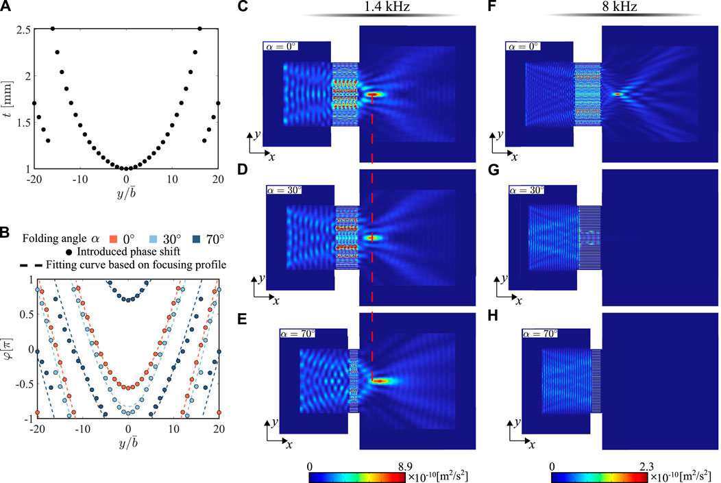
FIGURE 5. Wave focusing metasurface design with 16 facets under different folding angles for normally incident A0 mode wave at different frequencies. (A) The thickness profile of the foldable metasurface for localizing 1.4 kHz wave at 101.6 mm with folding angle α =0°. (B) The phase profiles of the metasurface under 1.4 kHz incident A0 mode wave and different folding angles. The square of out-of-plane velocity wavefields, |vz|2,with folding angle (C) α = 0°, (D) α = 30°, (E) α = 70° under 1.4 kHz A0 incident wave. The |vz|2 wavefields with folding angle (F) α = 0°, (G) α = 30°, (H) α = 70° under 8 kHz A0 incident wave.
Next, the metasurface is numerically tested by applying harmonic excitation at different frequencies and changing the folding angle in COMSOL Multiphysics. Figures 5C–E show the out-of-plane velocity squared wavefield |vz|2 under 1.4 kHz excitation and folding angles of α = 0°, 30°, and 70°. Results show that the origami-inspired metasurface can localize the transmitted A0 mode even with a large folding angle at 70°. In addition, the focal position remains almost unchanged under a small folding angle, e.g., α = 0°, and 30°, while the location of maximum wave intensity shifts to a further point when the metasurface is folded to 70°, as highlighted by the red dashed line in Figures 5C–E, matching with the prediction in the fitting curve in Figure 5B. The performance of the same metasurface is tested under 8 kHz, as plotted in Figures 5F–H. The energy of the A0 mode can still be localized at 100 mm for α = 0°, which is almost the same focal position under 1.4 kHz incident wave (i.e., 93 mm) due to the compensation between the changing in wavenumber and required phase gradient [5, 23]. When we fold the structure, the wave is prohibited from propagating in the transmitted region because 8 kHz is located inside the band gap of the metasurface with a folded state, as shown in Figure 2C. Hence, the performance of the focusing metasurface can be easily tuned by changing the folding angle of the system.
To quantitatively evaluate the change in focal position under 1.4 kHz flexural excitation, we calculate the velocity wavefields in the transmitted region along the centerline (y = 0) under different folding angles. For angles of α = [0°, 10°, 20°, 30°, 40°, 50°, 60°, 70°, 80°], the maximum out-of-plane velocities are achieved at [93, 92.4, 93.6, 67.4, 95.4, 95.2, 134, 129.3, 174.2] mm, respectively. The overall trends of maximum velocity results show that the folding angle has negligible effects on the focusing position under a small folding angle α < 45°. The metasurface with a folding angle greater than 45° will localize the wave energy at a further position. The maximum wave intensities occur at 93 and 129.3 mm under the folding angle of α = 0° and α = 70°, respectively, with only 8.46% and 3.36% deviation from the prediction. Note that there is a drop in the focusing position under α = 30° due to the change in the local transmission of the A0 mode for each metasurface unit, as indicated in Figure 4A. Accordingly, this variation results in a different distribution of the wave energy around the focal point. However, the overall focal region for α = 30° is still similar to α = 0°, as shown in Figures 5C, D. This phenomenon can be used in a wide range of engineering practices, where the metasurface could be adjusted to fit different spatial dimensions while still maintaining the desired performance of focusing and acting as a low-pass filter, forbidding the propagation of higher frequencies at a folded state.
4.2 Case II: Wave deflecting
This study investigates whether the proposed metasurface concept can achieve tunable wave-deflecting control by only folding the entire structure. Here, we elongate the metasurface unit and include 64 facets in the design to cover a more extensive range of phase shifts. The phase modulation curve of 1.4 kHz transmitted A0 mode under different facet thicknesses and folding angles are shown in Figure 6A. According to the generalized Snell’s law [1], to deflect the incoming A0 mode Lamb wave by an angle of θt in the transmitted region, the phase modulation φ(y) is applied as [51]:
where φ(y) is the required phase modulation at location y. Next, we tailor the thickness of the metasurface units to deflect normally incident A0 mode wave at 1.4 kHz by an angle of 45° under unfolded state, i.e., α = 0°, as presented in Figure 6B. Figure 6C shows the comparison of the phase gradients between numerical calculation and generalized Snell’s law, indicating that the same metasurface can deflect the incident A0 mode by 45° and 33° under a folding angle of α = 0° and α = 70°, respectively. By applying a harmonic boundary load at 1.4 kHz, we numerically test the metasurface in COMSOL Multiphysics frequency domain simulation. Figures 6D, E show the resulting out-of-plane velocity wavefields, where the transmitted elastic wavefront has been deflected by the angle of θt = 44° and θt = 33°, respectively, matching with the theoretical prediction based on GSL. The uneven energy distribution in the wavefront under α = 70° is because of the discretization effect of metasurface units and the change in local transmission ratios when folding the structure. Despite this small discrepancy, the numerical simulations successfully validate that the zigzag-formed metasurface can also achieve tunable wave-deflecting control depending on the folding angles.
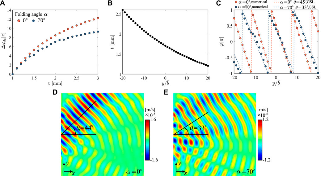
FIGURE 6. Wave deflecting metasurface design with different folding angles and 64 facets for normally incident A0 mode wave at 1.4 kHz. (A) Phase modulation curves of the metasurface unit with 64 facets under different facets’ thicknesses. (B) Thickness profile for wave deflecting metasurface design for deflecting 1.4 kHz wave by 45° with folding angle α =0°. (C) Comparison of the phase shift between the numerical results and generalized Snell’s law. The out-of-plane velocity wavefields under (D) α =0°, and (E) α =70°.
5 Experimental validation
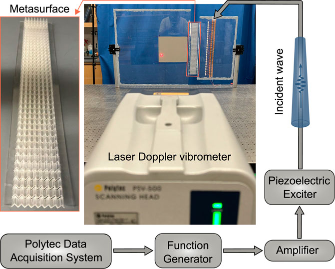
The performance of the origami-inspired metasurface is experimentally tested to validate the theoretical predictions and numerical results. We fabricated and experimentally tested the focusing metasurface under different folding angles. Since the main purpose of this study is to test the performance of the zigzag folded metasurface at other folding states, we adopted 3D print techniques to fabricate the metasurface with rigid creases. The metasurfaces are fabricated through Stratasys J850 3D Printer and used to connect two acrylic plates via epoxy. The Young’s modulus of the Veroclear is Ev = 2.545 GPa, which is obtained based on a three-point bending test. An array of thickness-mode piezoelectric patches (Steminc SM412, 12 × 0.6 mm) were used to excite incident plane waves in the substrate host plate. 4-cycle sine-burst signals at 1.4 and 8 kHz were generated with the function generator (KEYSIGHT 33210A) and power amplifier (TREK PZD350A). The out-of-plane velocity responses of the transmitted waves were measured via a Polytec PSV-500 scanning laser Doppler vibrometer (LDV). The experimental setup showing its different components is presented in Figure 7. A blu-tack is attached to the edges of the substrate plate to absorb the reflection and minimize the interference of the transmitted wave packet with the boundary reflections.
Figures 8A–C show the measured root-mean-square (RMS) distribution of the out-of-plane velocity fields, demonstrating the focusing phenomenon at the desired region under different folding angles. The normalized out-of-plane velocity along the centerline (y = 0) is shown in Figures 8D–F, demonstrating maximum out-of-plane velocity at 68.6, 80.5, and 98.4 mm for a folding angle of α = 0°, 30° and 70° in the experiment, respectively. Even though there are small discrepancies in the focal position due to the aperture size of the metasurface, potential anisotropic properties in 3D-printed material, and the epoxy layer between the metasurface and substrate, the overall trend of the measured velocity distribution around focus matches well with the numerical prediction. In addition, the experimental results show that the position of the maximum velocity shifts to a further position when the metasurface is folded to a large angle of α = 70°, matching with theoretical prediction. Furthermore, we tested the focusing metasurface performance under 8 kHz. The measured RMS distribution of the out-of-plane velocity fields is shown in Figures 8G–I. The unfolded-state metasurface (i.e., α = 0°) shows an achromatic wave-focusing capability as expected. When the metasurface is folded to α = 30° and α = 70°, the RMS velocity in the transmitted fields is negligible as expected, indicating that the energy is prohibited from propagating through metasurface since 8 kHz is located inside the band gap of the folded states.
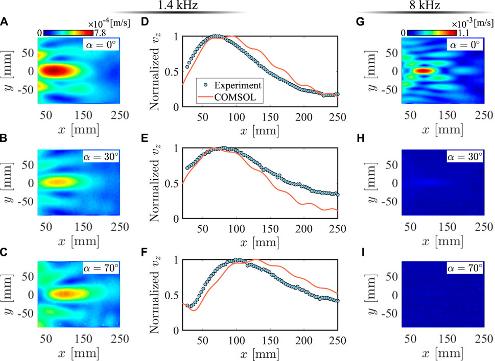
FIGURE 8. Experimental measurements of focusing metasurface designed for normally incident A0 wave mode at 1.4 and 8 kHz. RMS velocity wavefields in the transmitted region under 1.4 kHz and the folding angle of (A) α =0° (B) α =30° and (C) α =70°. Experimental normalized velocity results, vz, along the centerline (y = 0) of the metasurface under 1.4 kHz and the folding angle of (D) α =0° (E) α =30° and (F) α =70°, showing a very good agreement with the numerical prediction. RMS velocity wavefields in the transmitted region under 8 kHz and the folding angle of (G) α =0° (H) α =30° and (I) α =70°.
While this study only focused on folded states of the polymer-made metasurface with rigid connections, thus limiting the reconfigurability in real-time, the findings of this work can be expanded with further consideration of joint stiffness in the crease patterns that enable an actual origami-folded metasurface. In engineering practices, different folding mechanisms can be adopted according to the type of specific application, such as hinges at the crease [52–54], strained joint technique [53], multi-layer systems [55], thin creased and perforated sheets [56], etc. Furthermore, different materials or origami patterns can be selected to enable in situ reconfigurability of elastic wavefront shaping.
6 Conclusion
In summary, we propose an elastic metasurface composed of an array of zigzag-based folded sheets with parallel corrugations to control the wavefront of the refracted A0 Lamb mode wave. The metasurface can achieve reconfigurable performance depending on the folding angle and operating frequency. Our innovation and findings include (i) an origami-inspired metasurface adaptable to different geometrical scales, (ii) a zig-zag folding mechanism combined with a thickness tailoring technique for achieving tunable wavefront control depending on the folding angle and operating frequencies, and (iii) insights from unit cell analysis into tunable transmission and phase modulation by tailoring the folding angle of the proposed metasurface. With theoretical, numerical, and experimental efforts, this study presents an unconventional elastic wave control technique. The findings in this study can open the pathway for new applications of wave engineering in mechanical, civil, and aerospace structures.
Data availability statement
The raw data supporting the conclusions of this article will be made available by the authors, without undue reservation.
Author contributions
ZL: Conceptualization, Formal Analysis, Investigation, Methodology, Software, Validation, Writing–original draft, Writing–review and editing. ST: Conceptualization, Funding acquisition, Investigation, Project administration, Supervision, Writing–review and editing, Resources.
Funding
The authors declare financial support was received for the research, authorship, and/or publication of this article. This research was funded by the National Science Foundation under Grant No. CMMI-1933436.
Conflict of interest
The authors declare that the research was conducted in the absence of any commercial or financial relationships that could be construed as a potential conflict of interest.
Publisher’s note
All claims expressed in this article are solely those of the authors and do not necessarily represent those of their affiliated organizations, or those of the publisher, the editors and the reviewers. Any product that may be evaluated in this article, or claim that may be made by its manufacturer, is not guaranteed or endorsed by the publisher.
References
1. Yu N, Genevet P, Kats MA, Aieta F, Tetienne JP, Capasso F, et al. Light propagation with phase discontinuities: generalized laws of reflection and refraction. Science (2011) 334:333–7. doi:10.1126/science.1210713
2. Xu W, Zhang M, Ning J, Wang W, Yang T. Anomalous refraction control of mode-converted elastic wave using compact notch-structured metasurface. Mater Res Express (2019) 6:065802. doi:10.1088/2053-1591/ab0dc8
3. Li Y, Jiang X, Li R, Liang B, Zou X, Yin L, et al. Experimental realization of full control of reflected waves with subwavelength acoustic metasurfaces. Phys Rev Appl (2014) 2:064002. doi:10.1103/physrevapplied.2.064002
4. Qi S, Assouar B. Acoustic energy harvesting based on multilateral metasurfaces. Appl Phys Lett (2017) 111. doi:10.1063/1.5003299
5. Lin Z, Tol S. Elastic metasurfaces for full wavefront control and low-frequency energy harvesting. J Vib Acoust (2021) 143:061005. doi:10.1115/1.4050275
6. Jin Y, Wang W, Khelif A, Djafari-Rouhani B. Elastic metasurfaces for deep and robust subwavelength focusing and imaging. Phys Rev Appl (2021) 15:024005. doi:10.1103/physrevapplied.15.024005
7. Melde K, Mark AG, Qiu T, Fischer P. Holograms for acoustics. Nature (2016) 537:518–22. doi:10.1038/nature19755
8. Tian Y, Wei Q, Cheng Y, Liu X. Acoustic holography based on composite metasurface with decoupled modulation of phase and amplitude. Appl Phys Lett (2017) 110. doi:10.1063/1.4983282
9. Faure C, Richoux O, Félix S, Pagneux V. Experiments on metasurface carpet cloaking for audible acoustics. Appl Phys Lett (2016) 108. doi:10.1063/1.4941810
10. Fan SW, Zhao SD, Cao L, Zhu Y, Chen AL, Wang YF, et al. Reconfigurable curved metasurface for acoustic cloaking and illusion. Phys Rev B (2020) 101:024104. doi:10.1103/physrevb.101.024104
11. Assouar B, Liang B, Wu Y, Li Y, Cheng JC, Jing Y. Acoustic metasurfaces. Nat Rev Mater (2018) 3:460–72. doi:10.1038/s41578-018-0061-4
12. Xie Y, Wang W, Chen H, Konneker A, Popa BI, Cummer SA. Wavefront modulation and subwavelength diffractive acoustics with an acoustic metasurface. Nat Commun (2014) 5:5553–5. doi:10.1038/ncomms6553
13. Li Y, Jiang X, Liang B, Cheng J, Zhang L. Metascreen-based acoustic passive phased array. Phys Rev Appl (2015) 4:024003. doi:10.1103/physrevapplied.4.024003
14. Zhu H, Semperlotti F. Anomalous refraction of acoustic guided waves in solids with geometrically tapered metasurfaces. Phys Rev Lett (2016) 117:034302. doi:10.1103/PhysRevLett.117.034302
15. Liu Y, Liang Z, Liu F, Diba O, Lamb A, Li J. Source illusion devices for flexural lamb waves using elastic metasurfaces. Phys Rev Lett (2017) 119:034301. doi:10.1103/physrevlett.119.034301
16. Lee H, Lee JK, Seung HM, Kim YY. Mass-stiffness substructuring of an elastic metasurface for full transmission beam steering. J Mech Phys Sol (2018) 112:577–93. doi:10.1016/j.jmps.2017.11.025
17. Su X, Lu Z, Norris AN. Elastic metasurfaces for splitting sv-and p-waves in elastic solids. J Appl Phys (2018) 123:091701. doi:10.1063/1.5007731
18. Cao L, Yang Z, Xu Y, Assouar B. Deflecting flexural wave with high transmission by using pillared elastic metasurface. Smart Mater Struct (2018) 27:075051. doi:10.1088/1361-665x/aaca51
19. Su G, Zhang Y, Liu Y, Wang T. Steering flexural waves by amplitude-shift elastic metasurfaces. J Appl Mech (2021) 88:051011. doi:10.1115/1.4050239
20. Li B, Hu Y, Chen J, Su G, Liu Y, Zhao M, et al. Efficient asymmetric transmission of elastic waves in thin plates with lossless metasurfaces. Phys Rev Appl (2020) 14:054029. doi:10.1103/physrevapplied.14.054029
21. Hu Y, Zhang Y, Su G, Zhao M, Li B, Liu Y, et al. Realization of ultrathin waveguides by elastic metagratings. Commun Phys (2022) 5:62. doi:10.1038/s42005-022-00843-0
22. Cao L, Yang Z, Xu Y, Chen Z, Zhu Y, Fan SW, et al. Pillared elastic metasurface with constructive interference for flexural wave manipulation. Mech Syst Signal Process (2021) 146:107035. doi:10.1016/j.ymssp.2020.107035
23. Liu F, Yang Z, Shi P, Shen Y, Cao L, Xu Y. Refraction of flexural waves by ultra-broadband achromatic meta-slab with wavelength-dependent phase shifts. J Appl Mech (2022) 89:041003. doi:10.1115/1.4053201
24. Li S, Xu J, Tang J. Tunable modulation of refracted lamb wave front facilitated by adaptive elastic metasurfaces. Appl Phys Lett (2018) 112:021903. doi:10.1063/1.5011675
25. Xia R, Yi J, Chen Z, Li Z. In situ steering of shear horizontal waves in a plate by a tunable electromechanical resonant elastic metasurface. J Phys D: Appl Phys (2019) 53:095302. doi:10.1088/1361-6463/ab5cbc
26. Yaw Z, Zhou W, Chen Z, Lim C. Stiffness tuning of a functional-switchable active coding elastic metasurface. Int J Mech Sci (2021) 207:106654. doi:10.1016/j.ijmecsci.2021.106654
27. Shi P, Liu F, Xu Y, Yang Z. (2021). Tunable modulation of flexural waves by adaptive elastic metasurface. in 2020 15th Symposium on Piezoelectrcity, Acoustic Waves and Device Applications (SPAWDA). Zhengzhou, Henan Province, China, 16-19 April 2021, IEEE, 480–4.
28. Yaw Z, Zhou W, Lim C. Anomalous wave control by an adaptive elastic metasurface shunted with negative capacitance circuit. J Sound Vib (2022) 525:116782. doi:10.1016/j.jsv.2022.116782
29. Lin Z, Tol S. Electroelastic metasurface with resonant piezoelectric shunts for tunable wavefront control. J Phys D: Appl Phys (2023) 56:164001. doi:10.1088/1361-6463/acbd5f
30. Yuan SM, Chen AL, Wang YS. Switchable multifunctional fish-bone elastic metasurface for transmitted plate wave modulation. J Sound Vibration (2020) 470:115168. doi:10.1016/j.jsv.2019.115168
31. Yuan SM, Chen AL, Cao L, Zhang HW, Fan SW, Assouar B, et al. Tunable multifunctional fish-bone elastic metasurface for the wavefront manipulation of the transmitted in-plane waves. J Appl Phys (2020) 128:224502. doi:10.1063/5.0029045
32. Chen X, Liu P, Hou Z, Pei Y. Magnetic-control multifunctional acoustic metasurface for reflected wave manipulation at deep subwavelength scale. Scientific Rep (2017) 7:9050. doi:10.1038/s41598-017-09652-w
33. Adriaansen F. Corrugated polymeric zigzag sheet for greenhouse roof structures. US Patent 6,959,519 (2005).
34. Santer M, Pellegrino S. Concept and design of a multistable plate structure. J Mech Des (2011) 133:014304. doi:10.1115/1.4004459
35. Ning X, Pellegrino S. (2013). Imperfection-insensitive axially loaded cylindrical shells. in Proceedings of the 54th AIAA/ASME/ASCE/AHS/ASC Structures, Structural Dynamics and Materials Conference. Boston, MA, US, IEEE, 8–11.
36. Bartolozzi G, Baldanzini N, Pierini M. Equivalent properties for corrugated cores of sandwich structures: a general analytical method. Compos Structures (2014) 108:736–46. doi:10.1016/j.compstruct.2013.10.012
37. Bahabry RR, Kutbee AT, Khan SM, Sepulveda AC, Wicaksono I, Nour M, et al. Corrugation architecture enabled ultraflexible wafer-scale high-efficiency monocrystalline silicon solar cell. Adv Energ Mater (2018) 8:1702221. doi:10.1002/aenm.201702221
38. Lau JH. Stiffness of corrugated plate. J Eng Mech Division (1981) 107:271–5. doi:10.1061/jmcea3.0002696
39. Kheirikhah M, Babaghasabha V, Naeimi-Abkenari A, Khadem M. Free vibration analysis of corrugated-face sheet composite sandwich plates. J Braz Soc Mech Sci Eng (2016) 38:1973–85. doi:10.1007/s40430-015-0306-8
40. Kheirikhah M, Khadem M, Abkenari AN, Babaghasabha V, Khalili S. Buckling analysis of corrugated sandwich plates with soft core using three-dimensional finite element method. Icmet-asme Conf (2011) 3:477–84. doi:10.1115/1.859810.paper334
41. Kharoob OF, El-Hadidy AM, Hammad SA Linear investigation on tapered steel isolated plates with zigzag corrugated web. J Eng Res (2023) 7:171–6. doi:10.21608/ERJENG.2023.192152.1150
42. Han L, Zhang Y, Li XM, Jiang LH, Chen D. Tunable bandgaps in free/lock switchable foldable polyline-rod: an introduction of tunable phononic crystals independent of durable external factors. Appl Phys Express (2019) 12:127001. doi:10.7567/1882-0786/ab4f9f
43. Nanda A, Karami MA. Tunable bandgaps in a deployable metamaterial. J Sound Vibration (2018) 424:120–36. doi:10.1016/j.jsv.2018.03.015
44. Xu ZL, Xu SF, Chuang KC. Coupled flexural-longitudinal waves in an origami metamaterial with uncoupled creases. Phys Lett A (2021) 396:127232. doi:10.1016/j.physleta.2021.127232
45. Xu ZL, Yu SB, Liu J, Chuang KC. A tunable zig-zag reflective elastic metasurface. Crystals (2022) 12:1170. doi:10.3390/cryst12081170
48. Hakoda C, Rose J, Shokouhi P, Lissenden C. Using floquet periodicity to easily calculate dispersion curves and wave structures of homogeneous waveguides. AIP Conf Proc (2018) 1949:020016. doi:10.1063/1.5031513
49. Gupta V, Munian RK, Bhattacharya B. Dispersion analysis of the hourglass-shaped periodic shell lattice structure. Int J Sol Structures (2022) 254:111931. doi:10.1016/j.ijsolstr.2022.111931
50. Lin J, Li J, Jiang C, Chen X, Tang Z, Zeng Z, et al. Theoretical and experimental investigation of circumferential guided waves in orthotropic annuli. Ultrasonics (2022) 123:106715. doi:10.1016/j.ultras.2022.106715
51. Lin Z, Zhang Y, Wang K, Tol S. Anomalous wavefront control via nonlinear acoustic metasurface through second-harmonic tailoring and demultiplexing. Appl Phys Lett (2022) 121:201703. doi:10.1063/5.0101076
52. Lang RJ, Nelson T, Magleby S, Howell L. Thick rigidly foldable origami mechanisms based on synchronized offset rolling contact elements. J Mech Robotics (2017) 9:021013. doi:10.1115/1.4035686
53. Lang RJ, Tolman KA, Crampton EB, Magleby SP, Howell LL. A review of thickness-accommodation techniques in origami-inspired engineering. Appl Mech Rev (2018) 70:010805. doi:10.1115/1.4039314
54. Xing WC, Wang YQ. Vibration characteristics of thin plate system joined by hinges in double directions. Thin-Walled Structures (2022) 175:109260. doi:10.1016/j.tws.2022.109260
55. Faber JA, Arrieta AF, Studart AR. Bioinspired spring origami. Science (2018) 359:1386–91. doi:10.1126/science.aap7753
Keywords: elastic metasurface, reconfigurable metasurface, origami-inspired structure, elastic wavefront control, phase modulation
Citation: Lin Z and Tol S (2023) Shaping elastic wavefront through zigzag-folded metasurfaces. Front. Phys. 11:1304736. doi: 10.3389/fphy.2023.1304736
Received: 29 September 2023; Accepted: 20 November 2023;
Published: 11 December 2023.
Edited by:
Yunlan Zhang, The University of Texas at Austin, United StatesReviewed by:
Nicolás Guarín-Zapata, EAFIT University, ColombiaDi Wang, Purdue University, United States
Copyright © 2023 Lin and Tol. This is an open-access article distributed under the terms of the Creative Commons Attribution License (CC BY). The use, distribution or reproduction in other forums is permitted, provided the original author(s) and the copyright owner(s) are credited and that the original publication in this journal is cited, in accordance with accepted academic practice. No use, distribution or reproduction is permitted which does not comply with these terms.
*Correspondence: Serife Tol, c3RvbEB1bWljaC5lZHU=
 Zhenkun Lin
 Serife Tol