 A. Reddy
 H. Nassar
- Department of Mechanical and Aerospace Engineering, University of Missouri, Columbia, MO, United States
Shell mechanisms are patterned surface-like structures with compliant deformation modes that allow them to change shape drastically. Examples include many origami and kirigami tessellations as well as other periodic truss mechanisms. The deployment paths of a shell mechanism are greatly constrained by the inextensibility of the constitutive material locally and by the compatibility requirements of surface geometry globally. With notable exceptions (e.g., Miura-ori), the deployment of a shell mechanism often couples in-plane stretching and out-of-plane bending. Here, we investigate the repercussions of this kinematic coupling in the presence of geometric confinement, specifically in tubular states. We demonstrate that the confinement in the hoop direction leads to a frustration that propagates axially, as if by buckling. We fully characterize this phenomenon in terms of amplitude, wavelength, and mode shape in the asymptotic regime, where the size of the unit cell of the mechanism r is small compared to the typical radius of curvature ρ. In particular, we conclude that the amplitude and wavelength of the frustration are of order
1 Introduction
Origami tessellations are sheets of paper folded following a repetitive crease pattern. Beyond their artistic value, they now constitute a prototyping platform for a remarkable array of foldable and deployable structures useful in engineering [1]. Origami tessellations are often modeled as linkages: assemblies of rigid elements representing the facets of the origami, hinged along edges representing the crease lines. From this point of view, the kinematics of origami are no different from truss mechanisms. Thus, more generally, we call tessellation any linkage that is periodic (i.e., that is invariant by translation along a two-dimensional lattice of vectors), and we call folding any inextensional deformation that is compatible with the linkage kinematics. We suppose that the tessellation undergoes a uniform folding, i.e., a folding where fold angles remain periodic even if the linkage does not. Then, generically, the tessellation embraces a curved, often cylindrical, midsurface. Examples include the waterbomb tessellation, the Yoshimura pattern and the Ron Resch pattern [2], as well as the pyramidal truss mechanism illustrated in Figure 1A. Hence, it appears that the in-plane stretch, or contraction, due to the folding of a single unit cell is coupled to an out-of-plane bending motion that is necessary to maintain geometric compatibility among consecutive unit cells. We refer to tessellations that conform to this description as coupled. However, exceptions exist: there are tessellations that fold uniformly while maintaining a planar midsurface; we refer to them as planar. Examples of planar tessellations include the Miura-ori (Figure 1B), the eggbox pattern, and Chebyshev nets.
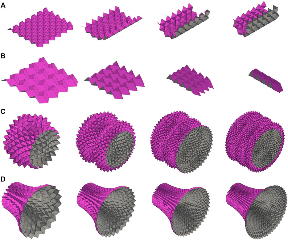
FIGURE 1. Coupled vs. planar tessellations. (A, B) Uniform foldings of a coupled (A) and planar (B) tessellation. (C, D) Demonstration of size effects, or lack thereof: finer coupled tessellations reveal finer features (c, this paper); finer planar tessellations stabilize (d, see [3–5]). It is to be noted that (C) and (D) feature non-uniformly folded states, i.e., states where folding angles vary in space.
Planar tessellations have received considerable attention in recent years and have been studied in the context of “geometric mechanics” by several authors. Schenk and Guest [6] and Wei et al. [7] computed Poisson’s coefficient of the Miura-ori and showed that it is equal to the ratio of normal curvatures observed in its anticlastic bending. Similar results were then obtained for the eggbox pattern [3], for the “morph” pattern [8], and, more recently, for a whole class of smooth and polyhedral surfaces of translation with straight or curved creases [5, 9–11]. Nassar et al. systematically leveraged the Poisson coefficient identity and classical differential geometric tools to compute the tubular states folded out of the Miura-ori [4], the eggbox pattern [3, 12], and the “Mars” tessellation [5]. Other origami tubes were designed and investigated by Tachi and Miura [13] and by Filipov et al. [14] with a focus on axial deployment. The foregoing results are remarkable but can hardly be extended to coupled tessellations mainly because of one difficulty: size dependence. Indeed, the midsurface geometry of a coupled tessellation greatly depends on the size of the creases: finer crease patterns produce tighter midsurfaces, with divergent curvatures (Figure 1C). Similarly, the waterbomb tessellation, the Ron Resch pattern, and the Yoshimura pattern all admit pairs of flat-unfolded and maximally-folded states, but the paths from one to the other necessarily go through curved states the curvatures of which are inversely proportional to the size of the creases. By contrast, the midsurface geometry of a planar tessellation, e.g., the Miura-ori, depends far more on the folding angles than on the size of the creases: finer crease patterns rapidly converge to a limit, non-singularly curved surface (Figure 1D).
The purpose of the present paper is to alleviate to some extent this difficulty: we propose a differential geometric framework for the characterization of the curved midsurfaces embraced by coupled tessellations under non-uniform foldings and provide appropriate asymptotic scalings for their size-dependent geometry. The framework is relevant for tessellations where the size r of the unit cell is small compared to the typical radius of curvature ρ of the embraced surface. Analysis of the folding of tubular states in particular reveals that confinement in the hoop direction causes bulges to develop at equal intervals in the axial direction, a phenomenon referred to here as “frustration propagation.” This phenomenon was recently studied numerically by Imada and Tachi [15] as a dynamical system with an area-preserving quality that explains periodicity. Here, we focus on the size-dependence of the frustration. Specifically, we show that, generically, the amplitude and wavelength of the frustration are of order
The paper begins by introducing one particular coupled tessellation in the form of a pyramidal truss mechanism. Uniform foldings and corresponding stretch–bend kinematics are explored first. Then, non-uniform foldings are described using the differential geometry of the midsurface. The key element is an equation that determines the metric of the midsurface in function of its curvatures and of a characteristic length scale. The theoretical implications are explored for tubular states, and the main results regarding frustration propagation are proven. Numerical solutions of the exact kinematics are shown to match the theoretical predictions.
2 Theory
2.1 Uniform foldings
Consider the pyramidal truss mechanism of Figure 1A initially introduced in [3]. Its unit cell is a spherical four-bar linkage with a single degree of freedom (DOF) assigned to either of the two central angles, θ and θ* (Figure 2). Let O designate the apex of a pyramid with side length r, and let (A, B, C, D) be the vertices at its base. Let (e1, e2, n) be an orthonormal basis such that e1 and e2 are, respectively, aligned with
with
Lastly, θ and θ* depend on one another through the constraint
A uniform folding is characterized by three elements: angle θ and two rotations L and R that map a unit cell to two of its neighbors. Compatibility requires that L and R commute, as shown in Figure 3A. Therefore, L and R share the same axis of rotation given by some unit vector t. Furthermore,
Thus, compatible axes of rotation t must be in the bisector plane of the dyad
Once φ is given, R and L are uniquely determined through (4). By iterating L and R, the whole folded state can be constructed out of a single unit cell. Given that L and R share the same axis t, and that t is invariant under the action of L and R, the folded state is found to be a cylinder of axis t. In conclusion, uniformly folded states constitute a 2-DOF family of cylinders parametrized by θ and φ: the former prescribes the folding angles within a unit cell, whereas the latter prescribes the folding angles between neighboring cells. For other tessellations that embrace similar cylindrical states, see [2, 16].
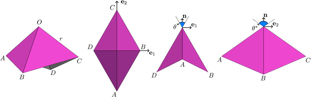
FIGURE 2. Annotated unit cell of the pyramidal truss mechanism: the truss is equilateral with side length r.
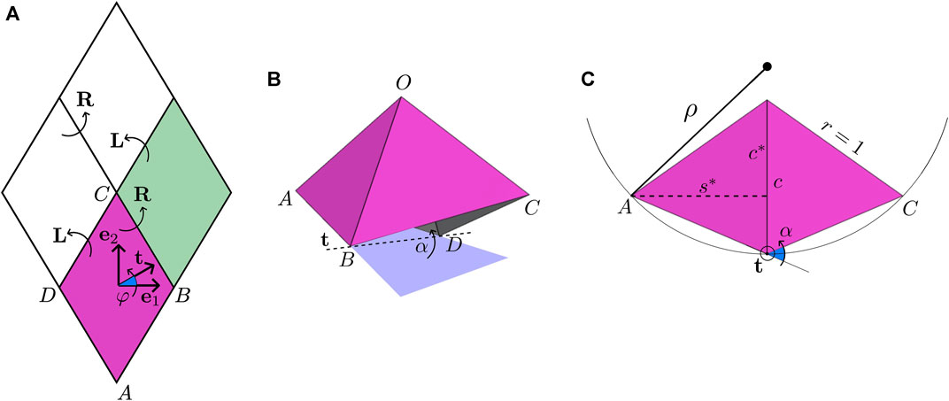
FIGURE 3. Analysis of uniform foldings. (A) Compatibility of rotations: arrows denote transitions between neighboring unit cells and not the axes of rotation. (B) Axis and angle of rotation in the particular case φ = 0. (C) Another view of (B) in the plane normal to t showing the radius of the cylindrical state: reported angles and lengths are measured in the normal plane assuming r = 1. For the full cylindrical state, refer to Figure 1B.
To gain further insight, let us explore the particular case φ = 0, i.e., where the axis of rotation t aligns with e1. Then, by symmetry, whatever rotation maps
Hence, based on the same figure, the radius of the embraced cylinder, as measured from the cylinder axis to the base of a pyramid, is expressed as
More generally, consider how a unit cell paves a cylinder by the repeated action of rotations, as shown in Figure 4A. By inspection of Figure 4B, the radius of curvature is
where α is the angle of rotation R and is given by
(see Figure 4C). Expanding the various dot products leads to
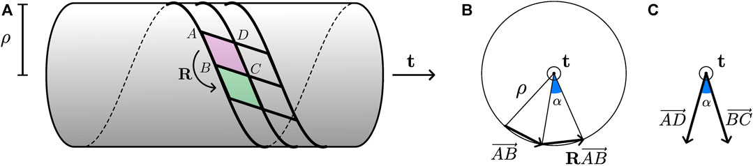
FIGURE 4. Geometry of a general uniformly folded state: (A) schematic view of the state; (B) axial view featuring quantities relevant to the determination of ρ; (C) same view featuring quantities relevant to the determination of α.
A generic uniform folding is illustrated in Figure 5A. Profiles of the normalized curvature r/ρ vs. angle φ are depicted in Figure 5B for various folding angles θ. The curvature is smallest (globally or locally) at φ = 0 and at φ = π/2, i.e., the least curved states are cylinders of axes e1 or e2. Furthermore, the radius of curvature ρ becomes comparable to r as soon as θ departs significantly from π/2. For θ = π/2, there is a singularity: in that case, all φ ≠ ± π/4 lead to the same planar state with zero curvature. For φ = ±π/4, the axis of the cylinder aligns with either side of the base and radius ρ can take any value larger than r.
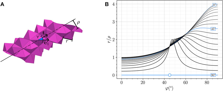
FIGURE 5. Variations of ρ relative to φ: (A) annotated generic uniform folding; (B) plot of r/ρ vs. φ for θ increasing from 0° to 90° by increments of 5° (as coded by line thickness). For θ = 90° and φ = 45° (marked with a circle), the curvature is indeterminate and can take any value smaller than 1.
2.2 Linearization
The aforementioned derivations show that any extension in direction e1 or e2, as measured by angle θ, is coupled to bending about some axis t with a radius of curvature ρ. Furthermore, ρ scales like r. In other words, for equal θ, finer tessellations wind more tightly. The divergence of the curvature in 1/r toward infinity as r decreases can only be avoided by limiting the magnitude of the folding angle θ to values close to π/2. Thus, henceforth, focus is on states such that
where γ represents a small relative extension. The idea behind this restriction is that it enforces r ≪ ρ in a way that makes it possible to speak of a smooth midsurface for more general, non-uniformly folded states. However, it is not clear how small γ should or will be compared to r/ρ, and both are kept as small independent parameters for the time being. Then, to leading order, the radius of curvature is
Beyond ρ, it will prove convenient to compute how the midsurface bends relative to directions e1 and e2. Specifically, let
Therein, E is the normal change in e1 transported to the next cell over in direction e1 across a distance DB; thus, it quantifies the normal curvature of the midsurface in direction e1; refer to Figure 3A for notations. Similarly, G quantifies the normal curvature in direction e2 and F quantifies the torsion of the midsurface. The angles of rotations L and R, called α and β, respectively, are given by Eq. 4 and read
to leading order in γ. Therefore,
It appears then that (Er/γ, Gr/γ, Fr/γ) depend solely on φ, meaning that these quantities must satisfy two algebraic constraints, namely,
These algebraic constraints define the accessible bent states as prescribed solely by the angular extension γ, regardless of φ ≠ ± π/4. The latter constraint, in particular, says that the Gaussian curvature vanishes, which is expected since cylinders have zero Gaussian curvature. The case φ = ±π/4 has been avoided, but should it arise, the restriction r ≪ ρ implies γ = 0 and both algebraic constraints remain valid.
Now, since these states all reside in the vicinity of the planar state (i.e., θ = π/2) and are accessible, a linear superposition should also be accessible, even if non-uniformly folded. For instance, by combining a state A bent about e1 (i.e., φA = 0 and γA ≠ 0) with a state B bent about e2 (i.e., φB = π/2 and γB ≠ 0), a doubly curved state is obtained that is extended through γ = γA + γB and the curvatures of which are given by E = EB, G = GA, and F = 0. Evidently, such a combined state will no longer be cylindrical or even have zero Gaussian curvature (i.e., EG − F2 ≠ 0), but, remarkably, it will still satisfy the first constraint, namely,
2.3 Differential geometry of the midsurface
Next, we make the scale transition in kinematic modeling from the discrete level to the continuum level. Let (ξ1, ξ2)↦x(ξ1, ξ2) parameterize the midsurface of a general, non-uniformly folded state. The in-plane deformations of the midsurface can be quantified using the metric tensor
Here, we identify
which implies, to first order in γ, that
As aforementioned, and in the following sections, it is understood that γ ≡ γ(ξ1, ξ2) can depend on space coordinates so as to allow for the continuum description to encompass non-uniformly folded states. The only restriction in that regard is that variations in γ should occur over length scales larger than r.
As for out-of-plane deformations, they are captured by the second fundamental form b = bij, where
Here too, we identify b11 ≡ E, b22 ≡ G, and b12 ≡ F so that the constraint
is systematically enforced point-wise, i.e., at all positions (ξ1, ξ2). Again, the other constraint, namely, det b = 0, only holds for uniformly folded states (i.e., γ = cste), but not in general.
Solving for the midsurface then amounts to finding surfaces the metric and second form of which,
It is worth highlighting that for several planar tessellations, including the Miura-ori and the eggbox pattern, as well as other patterns with no stretch-to-bend coupling, the coefficients of the second fundamental form b still satisfy a linear metric-dependent constraint similar to (21), albeit one that is homogeneous, e.g., of the form p(γ)b22 − q(γ)b11 = 0 [3–5]. Here, by contrast, the foregoing constraint exhibits a “source” term in γ/r that is both metric- and size-dependent.
3 Results
3.1 Geometry of tubular states
We define a tubular state as one that embraces a midsurface of revolution. Specifically, let
where ρ and z are to-be-determined functions, q ≡ 2π/W, and W is the width of the tessellation in the flat reference state; see Figure 6A. Then, computing x1, x2, and so on, we get
where a prime denotes d/dξ2. The key Eq. 22 then yields two ordinary differential equations (ODEs), namely,
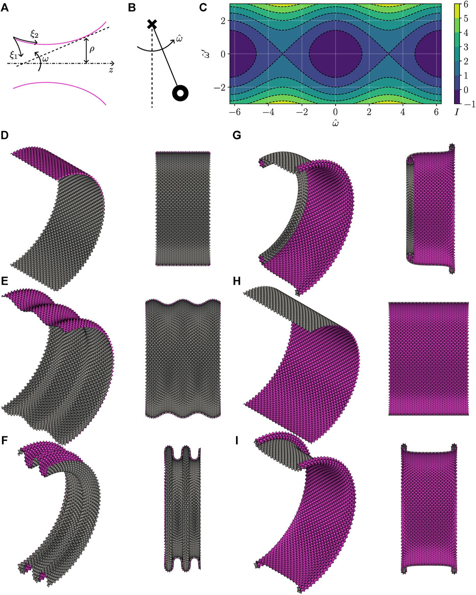
FIGURE 6. Tubular states. (A) Notations. (B) Simple pendulum analogy. (C) Phase diagram: iso-contours of the analog to mechanical energy I. (D–I) Two views of various tubular states for increasing I: (D, H) are uniformly folded states; the other states are non-uniformly folded.
In the following sections, we solve these equations in the asymptotic regime that is consistent with the adopted continuum description, i.e., in the limit where γ → 0 and r/ρ → 0.
3.2 Asymptotics of size dependence
We deal with Eq. 25 as algebraic equations to begin with. Then, up to an error smaller than γ,
and there exists a function ω ≡ ω(ξ2) such that
since, now to the leading order in γ, we have ρ′2 + z′2 = 1. Substituting back into Eq. 24 for γ then yields
where terms in γ2 and in γqr = O(γr/ρ) are neglected, both being small relative to γ. Taking the derivative d/dξ2 and replacing γ′ with its leading-order expression in terms of qρ′ lead to
However, ω′ is of order b22 ≪ 1/r, meaning that, to the leading order, ω is the solution to the second-order ODE
Therefore, it appears that ω oscillates at a length scale
Accordingly, it is appropriate to re-scale the ξ2 coordinate and introduce a function
Then,
Note that further linearization of the elastica ODE is not warranted in general since there is no reason for ω to be small unless further assumptions regarding the smallness of the initial conditions
or by re-scaling
By analogy with the simple pendulum (Figure 6B), we know that sin ω, a quantity analogous to the horizontal deflection of the pendulum, oscillates periodically with zero average. Hence, ρ oscillates periodically with an amplitude of order
Note that the initial value zo is arbitrary and inconsequential because it amounts to a rigid body translation along the axis of revolution. As for ρo, it can be obtained by reconsidering the expression of γ, namely,
where terms of order qr = O(r/W) are neglected in favor of terms of order
and with it an expression for ρo in function of
Lastly, it is worthwhile to shed some light on the normal curvatures b11 and b22. On one hand, ω = arctan(ρ′/z′) is the incidence angle of the tangent plane relative to the axis of revolution. Its derivative can directly be interpreted as the normal curvature in the axial direction, specifically
This normal curvature increases in the limit r → 0 and is of order
and remains finite, being of order 1/W.
3.3 Phase diagram
The elastica ODE admits an invariant analogous to the mechanical energy of the simple pendulum
The iso-contours of I define the solution orbits in the
where the sign is positive for ω = 0 and negative for ω = π. In other words, achieving a cylindrical state requires closing the pyramids slightly (as seen in the axial direction) when the pyramids are pointing outward and opening them slightly when they are pointing inward.
Interestingly, these two fixed points have different stability properties. The cylindrical state with the pyramids pointing out is stable: deviations lead to oscillations that increase throughout the profile at once (Figures 6D–F). By contrast, the cylindrical state with the pyramids pointing in is unstable: deviations lead to oscillations growing at localized intervals that, should self-penetration be precluded, cannot exist except at the edges of the tubular state (Figures 6G–I). These edge states correspond to a simple pendulum that remains near the top (unstable) equilibrium position most of the time and that, however swiftly, swings by the bottom (stable) equilibrium position.
3.4 Numerical solutions and error analysis
The tessellations produced throughout the paper and in Figure 6 in particular are rendered by solving the exact discrete kinematics. The solution algorithm proceeds iteratively by constructing the nodes of the folded state one “zigzag” at a time, as illustrated in Figure 7A. Mainly, given the nodes that belong to zigzag number i, the nodes of zigzag number i + 1 can be constructed by completing the bases of the pyramids that are enclosed between zigzags i and i + 1, one pyramid at a time. This is possible because each enclosed pyramid has a unique degree of freedom. Further details can be found in [3, 4]. The algorithm is implemented in Python, and its code is available online (see Data availability). Here, rotation symmetry is leveraged and the algorithm can be initialized simply by providing the three parameters (r/W, θo, ωo), where θo = π/2 − γo. Profiles of γ are computed for small but finite r by solving the discrete kinematics and are shown in Figure 7B. The profile of γ obtained by solving the elastica ODE is shown as well. The plots demonstrate that the discrete solution, hereafter denoted as γdiscrete, converges to the continuous one, hereafter denoted as γODE. The convergence error
is further computed over a normalized r-independent range 0 ≤ ξ2/L ≤ T and is plotted in Figure 7C. Note that the γ profiles are normalized as well as anticipated by Eq. 36. The logarithmic scale shows that the error e decays with the side length r like r1/2.
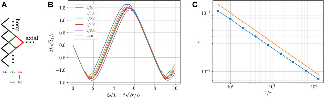
FIGURE 7. Convergence analysis. (A) Schematics of the discrete solution algorithm: knowledge of zigzag i suffices to uniquely determine zigzag i + 1. (B) Normalized folding angle γ vs. normalized discrete curvilinear coordinate as measured by a nodal index i: curves are obtained for decreasing r (see legend); the limit r → 0 is the solution to the elastica ODE. (C) Convergence speed: data points show the mean quadratic error e as obtained from (B); the seamless line shows the trend e = r1/2. Analysis is carried out for
4 Conclusion
The paper proposes a differential geometric framework that allows us to study the size-dependent kinematics of coupled tessellations, i.e., of periodic foldable structures, where in-plane folding is coupled to out-of-plane bending. The framework succeeds in predicting size effects both qualitatively and quantitatively for tubular states, where hoop confinement produces a frustration that propagates axially. The convergence of the framework is somewhat slow, with the error being of order r1/2, where r is a small size parameter. Thus, improvements that take higher-order corrections into account are desirable as they can improve convergence speed. In principle, such corrections will intervene at two places: in the linearization of the discrete kinematics and in the asymptotics of the governing non-linear ODE.
The main conclusion of the analysis, i.e., that axisymmetric frustrations are an elastica-shaped periodic with wavelength and amplitude of order r1/2, is not specific to the current pyramidal truss mechanism and should be typical of coupled tessellations that satisfy two properties: (i) the coupling is linear, meaning that g = g(b) is linear (affine strictly speaking), and (ii) the tessellation is rectangular so that the coordinate lines aligned with the axes of symmetry deform without shearing. Under these conditions, Eq. 19 is generic and is sufficient for our conclusion to hold. That being said, extensions to other potentially non-linearly coupled or oblique tessellations are of interest as well and are yet to be investigated.
Data availability statement
The datasets presented in this study can be found in online repositories. The names of the repository/repositories and accession number(s) can be found at: https://github.com/nassarh/pyramids.
Author contributions
AR: formal analysis, investigation, software, validation, visualization, and writing–original draft. AK: formal analysis, investigation, and writing–original draft. HN: conceptualization, formal analysis, funding acquisition, methodology, software, supervision, validation, visualization, and writing–review and editing.
Funding
The author(s) declare financial support was received for the research, authorship, and/or publication of this article. This work was supported by the NSF under CAREER award No. CMMI-2045881.
Acknowledgments
HN thanks Arthur Lebée (École des Ponts) for insightful exchange.
Conflict of interest
The authors declare that the research was conducted in the absence of any commercial or financial relationships that could be construed as a potential conflict of interest.
Publisher’s note
All claims expressed in this article are solely those of the authors and do not necessarily represent those of their affiliated organizations, or those of the publisher, the editors, and the reviewers. Any product that may be evaluated in this article, or claim that may be made by its manufacturer, is not guaranteed or endorsed by the publisher.
References
2. Tachi T. Rigid folding of periodic origami tessellations. In: K Miura, T Kawasaki, T Tachi, R Uehara, RJ Lang, and P Wang-Iverson, editors. Proceedings of the 6th international meeting of origami science, math, and education (6OSME): I. Mathematics (2015). p. 97–108. doi:10.1090/mbk/095.1/10
3. Nassar H, Lebée A, Monasse L. Curvature, metric and parametrization of origami tessellations: theory and application to the eggbox pattern. Proc R Soc A (2017) 473:20160705. doi:10.1098/rspa.2016.0705
4. Nassar H, Lebée A, Monasse L. Fitting surfaces with the Miura tessellation. In: RJ Lang, M Bolitho, and Z You, editors. Origami 7. Oxford: HAL Open Science (2018). p. 811–26.
5. Nassar H, Lebée A, Werner E. Strain compatibility and gradient elasticity in morphing origami metamaterials. Extreme Mech Lett (2022) 53:101722. doi:10.1016/j.eml.2022.101722
6. Schenk M, Guest SD. Geometry of miura-folded metamaterials. Proc Natl Acad Sci USA (2013) 110:3276–81. doi:10.1073/pnas.1217998110
7. Wei ZY, Guo ZV, Dudte L, Liang HY, Mahadevan L. Geometric mechanics of periodic pleated origami. Phys Rev Lett (2013) 110:215501. doi:10.1103/physrevlett.110.215501
8. Pratapa PP, Liu K, Paulino GH. Geometric mechanics of origami patterns exhibiting Poisson's ratio switch by breaking mountain and valley assignment. Phys Rev Lett (2019) 122:155501. doi:10.1103/physrevlett.122.155501
10. Nassar H. Isometric deformations of surfaces of translation. Mathematics and mechanics of complex systems (2023). arXiv:2310.08505.
11. Karami A, Reddy A, Nassar H. Curved-crease origami for morphing metamaterials (2023). arXiv:2310.08520.
12. Nassar H, Lebée A, Monasse L. Macroscopic deformation modes of origami tessellations and periodic pin-jointed trusses: the case of the eggbox. Proc IASS (2017).
13. Tachi T, Miura K. Rigid-Foldable cylinders and cells. J Int Assoc Shell Spat Structures (2012) 53:217–26.
14. Filipov ET, Tachi T, Paulino GH. Origami tubes assembled into stiff, yet reconfigurable structures and metamaterials. Proc Natl Acad Sci USA (2015) 112:12321–6. doi:10.1073/pnas.1509465112
15. Imada R, Tachi T. Undulations in tubular origami tessellations: a connection to area-preserving maps. Chaos (2023) 33. doi:10.1063/5.0160803
Keywords: compliant shell mechanisms, origami, foldable structures, continuum mechanisms, frustration, undulation, stretch–bend coupling, asymptotic analysis
Citation: Reddy A, Karami A and Nassar H (2023) Frustration propagation in tubular foldable mechanisms. Front. Phys. 11:1296661. doi: 10.3389/fphy.2023.1296661
Received: 18 September 2023; Accepted: 16 November 2023;
Published: 13 December 2023.
Edited by:
Yang Li, Wuhan University, ChinaReviewed by:
Paolo Celli, Stony Brook University, United StatesCharles Dorn, ETH Zürich, Switzerland
Yucai Hu, Hefei University of Technology, China
Copyright © 2023 Reddy, Karami and Nassar. This is an open-access article distributed under the terms of the Creative Commons Attribution License (CC BY). The use, distribution or reproduction in other forums is permitted, provided the original author(s) and the copyright owner(s) are credited and that the original publication in this journal is cited, in accordance with accepted academic practice. No use, distribution or reproduction is permitted which does not comply with these terms.
*Correspondence: H. Nassar, bmFzc2FyaEBtaXNzb3VyaS5lZHU=