 Hanxun Xu
 Renkai Li1
 Yingchao Du
95% of researchers rate our articles as excellent or good
Learn more about the work of our research integrity team to safeguard the quality of each article we publish.
Find out more
ORIGINAL RESEARCH article
Front. Phys. , 06 November 2023
Sec. High-Energy and Astroparticle Physics
Volume 11 - 2023 | https://doi.org/10.3389/fphy.2023.1292194
This article is part of the Research Topic Advancements in Free-Electron Radiation Sources and Particle Accelerators View all 5 articles
In this study, we propose a physical design of a compact all-optical terahertz (THz)-driven electron source. The 300-mm accelerator beamline, powered by a Joule-level laser system, can be easily integrated into the tabletop scale. A THz-driven electron gun, a tapered dielectric-loaded cylindrical waveguide, THz-driven bunch compressors, and permanent magnetic solenoids (PMSs) have been designed and optimized. Dynamic simulations show that the electron source can deliver 19 fC electron beams at 3 MeV, with a normalized transverse emittance of 0.079 π.mm.mrad. A minimum relative energy spread of 0.04% or a minimum root-mean-square (RMS) bunch length of 6.1 fs can be achieved. Sensitivity analysis shows that the THz-driven electron source can effectively work with a laser power jitter within 1.5%. Simulation studies also reveal the potential of the designed THz-driven electron source for achieving high-quality ultrafast electron diffraction (UED). Prototype THz-driven electron guns have been fabricated and are currently under testing, and more comprehensive results will be reported in future works.
Conventional particle accelerators are powerful tools for the development of modern science and technology. Owing to the radio-frequency-induced plasma breakdown [1–3], the acceleration gradients of microwave structures are difficult to be improved, resulting in large and expensive accelerator facilities. Novel acceleration techniques have been proposed to produce and sustain higher acceleration gradients, thus shrinking the accelerator size and cost. One promising technique is to up-convert the work frequency of the accelerator from microwaves to terahertz waves [4–6] or optical regimes [7–9], since a higher frequency and shorter pulse length contribute to a higher breakdown threshold. Plasma wakefield accelerations [10–12] have garnered attention, which use intense laser pulses or high-density electron bunches to produce strong wakefield accelerations for accelerating particles. Recently, the acceleration and manipulation of high-quality electron beams using THz waves have shown their great potential for achieving tabletop accelerators. THz-driven acceleration offers a GV/m acceleration gradient and pC-level bunch charge, providing a good compromise between conventional acceleration and direct laser acceleration. The millimeter-scale structures also relieve the manufacturing difficulties and timing control tolerances. Great progress has been made in THz-based electron guns [4, 13], linear acceleration [5, 6, 14] staging [15–17], streaking [18, 19], and compression and timing jitter suppression [20, 21], making it feasible to build real THz-driven accelerators.
In this paper, we report the physical design of a compact all-optical THz-driven electron source based on our previous works [16, 22–24] at Tsinghua University. The general design of the accelerator beamline and the required power system is proposed. A dual-feed THz-driven electron gun with an exponential impedance has been designed and fabricated to produce a 20 fC electron beam at 55 keV. A tapered dielectric-loaded cylindrical waveguide has been developed to boost the beam to 3 MeV. The beam shaping component, including two THz-driven compressors and three permanent magnetic solenoids, will also be presented. Dynamic simulations are carried out to optimize transverse emittance and minimize the relative energy spread or the root-mean-square (RMS) bunch length. Sensitivity analysis has been carried out to determine the impact of the THz energy jitter on the beam qualities. Simulation of the diffraction pattern of the aluminum sample using the generated electron beam also shows that the designed THz-driven electron source holds great potential for achieving high-quality MeV UED facilities. The current status of this project is also presented in this paper.
Figure 1 shows the schematic of the compact all-optical THz-driven electron source. The accelerator beamline consists of an injector followed by a beam shaping line. A 30 fs (FWHM) ultraviolet laser illuminates the copper cathode of the THz gun, generating the photo-electron bunch. Two single-cycle THz pulses of 0.45 THz and 108 μJ drive the dual-feed THz gun, exciting the TE01 mode electromagnetic field, which accelerates the photo-electron bunch from rest to 55 keV. The compressor downstream the gun compresses the beam with two single-cycle THz pulses of 0.45 THz and 2 μJ. A tapered dielectric-loaded waveguide (DLW), powered by a 0.45 THz, 280 ps (FWHM), 2.64 mJ THz wave, boosts the compressed beam to 3 MeV. A PMS enclosing the DLW has been designed to optimize the transverse emittance at the exit of the injector. Two PMSs and a DLW compressor are employed downstream the injector to configure the beam shape and bunch length. The DLW compressor can also work at the post-acceleration stage to further increase the beam energy. The total length of the beamline is approximately 300 mm, while the length of the injector is only 25 mm. This compact THz-driven accelerator beamline can be easily integrated to the tabletop size.
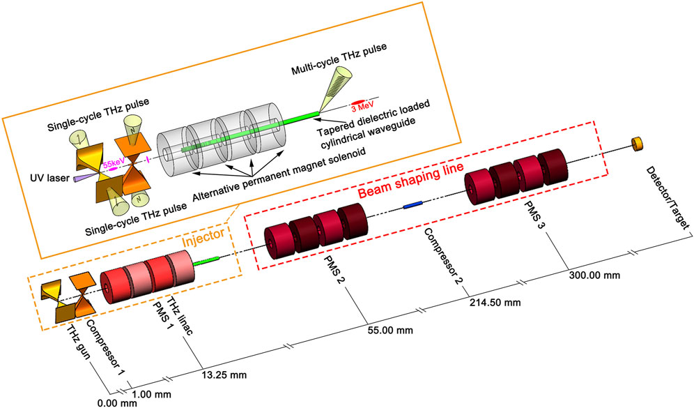
FIGURE 1. Schematic of the compact all-optical THz-driven electron source.
The THz-driven electron accelerator works at 0.45 THz and is powered by a Joule-level infrared laser system, as shown in Figure 2. The photocathode-driven laser is generated from infrared lasers via the optical third harmonic generation method. The single-cycle THz pulses driving the THz gun and THz compressor 1 are produced by optical rectification with a laser-THz conversion efficiency of approximately 1% [24, 25]. The optical generation of sub-mJ-level narrowband THz radiation based on periodically poled lithium niobate (PPLN) has been demonstrated [26]; this approach can be further developed to generate the mJ-level multi-cycle THz pulse that is required to drive the THz linac. The few-cycle THz pulses driving the DLW compressor 2 are produced by combining the optical rectification approach with a pulse stacking method [25]. All the THz waves and the photocathode-driven laser are generated from the same seeding laser, which benefits the inherent synchronization between the THz field and the electron bunch. One can also pump the sample with a split infrared laser and then probe the dynamic process using the generated electron bunch; this pump-probe setup enables a precise temporal resolution supported by the inherent synchronization between the pump laser and the probe electron beam.
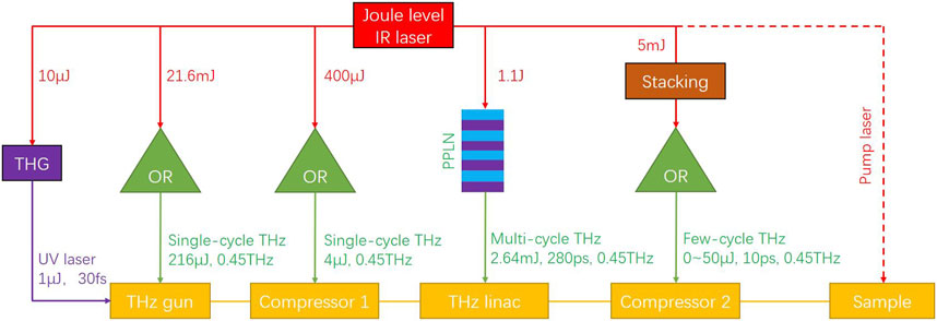
FIGURE 2. Power system of the compact all-optical THz-driven electron source.
The dual-feed THz-driven electron gun is a tapered rectangular waveguide with an exponential impedance along the wave propagation direction, as shown in Figure 3A. The tapered waveguide focuses the electric field and magnetic field simultaneously. The dual-feed work scheme enables a stronger acceleration field while eliminating the magnetic deflecting force. An exponential impedance variation benefits a higher coupling efficiency and broadens the coupling bandwidth. Assuming Cartesian coordinates whose origin is located at the gun center, the x/z-axis is parallel to the waveguide width/height direction, and the y-axis is in the THz propagation direction. The wave impedance of the TE10 mode in a rectangular waveguide is given as follows:
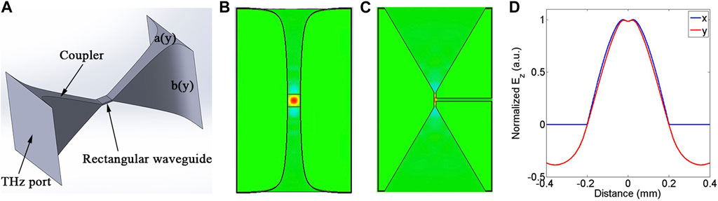
FIGURE 3. Dual-feed THz-driven electron gun. (A) Vacuum structure of the gun; (B) distribution of the acceleration field in the x-y plane; (C) distribution of the acceleration field in the z-y plane; and (D) normalized acceleration field amplitude along the x- and y-axis.
where
where A and B are the coefficients determined by the waveguide dimension and L is the half length of the gun. The gun is located in the focus spot of the THz wave, where the THz beam could be described by a Gauss beam. To further increase the coupling efficiency, the waveguide height also varies in a similar form as the beam waist of a Gauss beam:
where b0 and k are the coefficients determined by the waveguide dimension and L1 is the half length of the uniform waveguide at the gun center. CST [27] simulations have been carried out to optimize the coupling efficiency and the field distribution of the gun powered by a single-cycle THz wave reported in [25]. Figures 3A–D show the distribution of the acceleration field in the cross sections of the gun. The acceleration field in the gun center has been optimized to be homogeneous and symmetric, which will contribute to a smaller transverse emittance growth. A field enhancement of 3.5 is obtained at the gun center.
Figure 4 shows the dynamic simulation results of the THz gun using CST PIC Studio software. The initial electron beam is generated via the ASTRA [28] code. The temporal profile of the driven laser is 30 fs FWHM with a Gaussian distribution. The transverse intensity distribution is homogeneous with a radius of 25 μm. Powered by two 108 μJ single-cycle THz pulses, the gun successfully accelerates the initial beam from rest to 55 keV with an RMS energy spread of 0.8 keV. The normalized transverse emittance at the gun exit is 0.013 π.mm.mrad with a bunch charge of 20 fC. Owing to the space charge effect and the energy spread-induced speed divergence, the bunch length grows linearly after it is emitted from the gun exit.
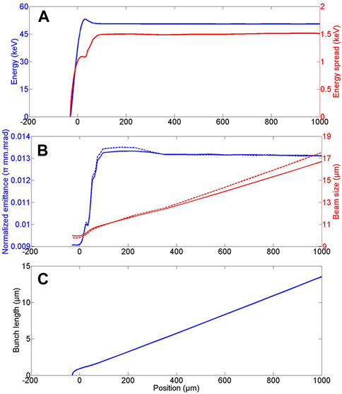
FIGURE 4. Dynamic simulation results of the THz gun. (A) Mean energy and RMS energy spread; (B) normalized transverse emittance and RMS beam size; solid/dotted lines are the parameters in the x/y direction; (C) RMS bunch length.
The main linac is a 16.5-mm tapered DLW with a constant inner diameter of 400 μm. The speed of the nonrelativistic electron beam increases significantly when they are accelerated by the THz field. We taper the dielectric (Al2O3, εr = 10.56) thickness of the DLW so that the phase velocity of the THz field matches the speed of the electron beam. Lemery F et al. have derived an analytical model to describe the field evolution and the beam dynamics of a tapered DLW [29]. Moreover, we use CST MWS Studio to design and optimize the DLW parameters. Figure 5 shows the simulation results of the designed tapered DLW. The field amplitude increases along the propagation direction of the THz wave since the dielectric thickness decreases along this direction. The main linac boosts the beam from the THz gun exit to 3 MeV with a 0.45 THz, 2.64 mJ, 280 ps THz wave. The effective acceleration gradient of the tapered DLW is 182 MV/m, with a peak field of 285 MV/m.
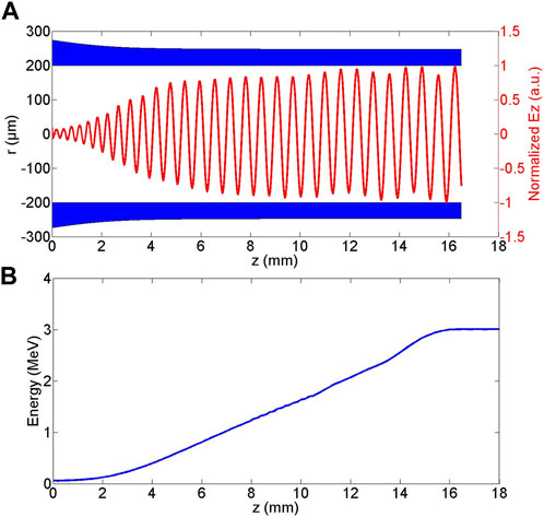
FIGURE 5. Tapered DLW. (A) Dielectric dimension and the normalized field amplitude; (B) energy variation in the single particle simulation.
To achieve higher acceleration efficiency, the phase bandwidth taken by the electron needs to be as narrow as possible. The wavelength of the THz wave at the main linac entrance/exit is 0.29/0.67 mm. For a 10° phase bandwidth, the corresponding beam length is 8/18.5 μm. Due to the strong space charge effects, the bunch length grows quickly after being emitted from THz gun, as shown in Figure 4C. A THz bunch compressor is located after the gun to compress the bunch length. This compressor shares the same waveguide structure as the THz gun while working at a zero-cross phase, as shown in Figure 6. Owing to the speed divergence and energy spread, the beam emitted from the gun has a negative energy chirp, and the electron energy at the bunch head is higher than that at the bunch tail. When injected at the negative gradient zero-cross phase, the bunch head is decelerated, while the bunch tail is accelerated. The energy chirp will be flipped under certain THz field strength. The beam energy at the beam head is lower than that at the bunch tail after leaving the bunch compressor. In the following drift space, the electrons at the bunch tail catch the electrons at the beam head as velocity bunching takes place. When the high-energy electrons surpass the low-energy electrons and form the bunch head, the energy chirp flips and the beam begins to stretch again. Figure 6B shows velocity bunching when the bunch compressor is located 1 mm downstream the THz gun. With two pulses of 2 μJ THz, the beam is compressed to a minimum RMS bunch length of 6 μm at z = 5 mm. The energy spread decreases from 0.8 keV to 0.1 keV.
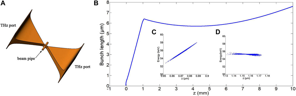
FIGURE 6. Rectangular waveguide compressor. (A) Geometry of the compressor; (B) RMS bunch length along the beamline. Inset: The longitudinal phase space at the compressor entrance (C) and exit (D).
A uniform DLW has been designed to manipulate the longitudinal phase space of the electron beam produced by the injector. The relativistic electron beam from the injector moves faster than the nonrelativistic beam from the THz gun. The interaction slit of the rectangular compressor is 60 μm, corresponding to a short interaction time, which requires much higher single-cycle THz pulse energy to flip the energy chirp. The interaction length of a uniform DLW depends on the designed phase velocity, group velocity, and the THz pulse length; thus, a longer interaction length could be achieved by employing a long uniform DLW powered by a relatively lower-energy few-cycle THz pulse. Moreover, the transverse Lorentz force in the DLW tends to be zero when the electron velocity tends to the speed of light, contributing to a lower transverse emittance growth. Figure 7A shows the geometry of the designed DLW, which is a 3-mm uniform quartz capillary with an inner diameter of 300 μm and a dielectric thickness of 92 μm. The longitudinal THz field is optimized to be fairly homogeneous in the vacuum regime. Figure 7B shows the dispersion curve of the DLW, with the phase velocity of 0.9894 c and a corresponding group velocity of 0.0304 c. The DLW compressor is driven by the dynamic simulation of a 10 ps, 0.45 THz pulse, and the interaction length between the THz wave and the electron is 2.5 mm.
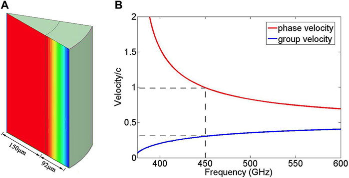
FIGURE 7. Uniform DLW compressor. (A) Dimension and the field distribution of the DLW; (B) dispersion curve of the DLW.
In order to avoid charge loss and to compensate the transverse emittance growth, we design two types of PMSs by scaling the PMSs developed by REGAE at DESY [30] to focus the electron bunch. PMSs provide stronger focusing strength and smaller weight and size than electromagnets. The designed PMSs consist of four circular magnets; each circular magnet consists of 12 circular sectors made of neodymium (NdFeB) magnets, as shown in Figure 8A. The remanence field of each sector is 1.47 T, with opposite magnetic directions in the adjacent circular magnets. Figure 8B shows the distribution of the magnetic field of the PMS. There are three PMSs in the beamline: PMS1 encloses the low-energy regime for emittance compensation, PMS2 focuses the beam to the DLW compressor, and PMS3 focuses the beam at the end of the beamline. Figure 8C shows the longitudinal magnetic field distribution of PMS1/PMS2, with a peak field of 1.05/0.95 T. PMS3 shares the same parameters of PMS2.
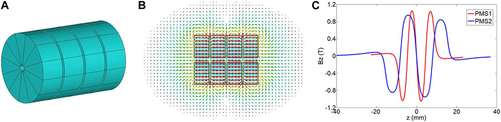
FIGURE 8. Alternative permanent magnetic solenoid. (A) Geometry of the PMS; (B) magnetic field distribution of the PMS; and (C) longitudinal magnetic field along the PMS vacuum axis.
In order to minimize the transverse emittance at the exit of the injector, we optimize the position and strength of the compensating magnet PMS1 and the main linac as well as the rectangular waveguide compressor via CST and ASTRA simulation. The optimized injector parameters are listed in Table 1, and the beam parameter evolutions are shown in Figure 9. The mean energy of the electron bunch is 3.00 MeV, with an RMS energy spread of 25.94 keV, corresponding to a relative energy spread of 0.86%. The beam is finely focused with a normalized transverse emittance of 0.073 π mm.mrad. Owing to the space charge repulsion and fly speed divergence, the bunch length continues to grow after leaving the main linac, which requires further compression.
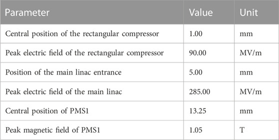
TABLE 1. Optimized parameters of the injector.
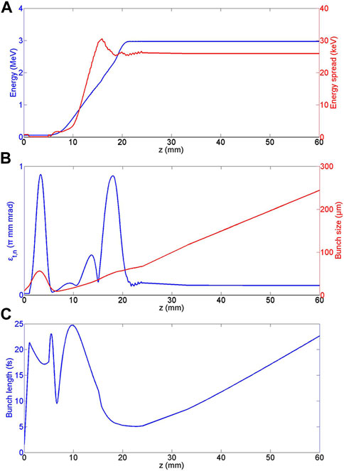
FIGURE 9. The evolution of the phase space parameters of the injector. (A) the mean energy and r.m.s. energy spread, (B) the normalized transverse emittance and the r.m.s. bunch size, (C) the r.m.s. bunch length.
The bunch length and energy spread at the end of the beamline are controlled by the beam shaping line. A minimum energy spread is preferred by many static applications, such as static ultrafast electron diffraction and ultrafast electron microscopy since a quasi-monochromatic beam will achieve a higher spatial resolution. However, most pump–probe experiments prefer a minimum bunch length so that it can probe the sample with a smaller time step. To address the aforementioned issues, we sweep the THz energy of the DLW compressor to find the corresponding configurations for a minimum bunch length or a minimum energy spread, as shown in Figure 10A. A minimum RMS bunch length of 2.1 keV, corresponding to a relative energy spread of 0.08%, is achieved at 6 μJ THz energy with an RMS bunch length of 106.3 fs. When the THz energy is increased to 50 μJ, a minimum RMS bunch length of 6.1 fs arises with a relative energy spread of 1.69%. Afterward, the bunch length slowly increases since the beam is over compressed. Figure 10B shows the normalized transverse emittance as a function of the THz energy driving the compressor. The transverse Lorentz force focuses the beam at the compression phase, which leads to the decrease in emittance. When velocity bunching takes place, the emittance of the compressed beam will increase owing to the Panofsky–Wenzel theory. The total effects of transverse focusing and longitudinal compression contribute to the emittance decrease at the beginning and emittance increase after reaching a minimum of 0.078 π mm.mrad. The relative difference of emittance in the range of 0–80 μJ is less than 2.5%; the DLW could effectively adjust the energy spread and the bunch length while preserving bunch emittance.
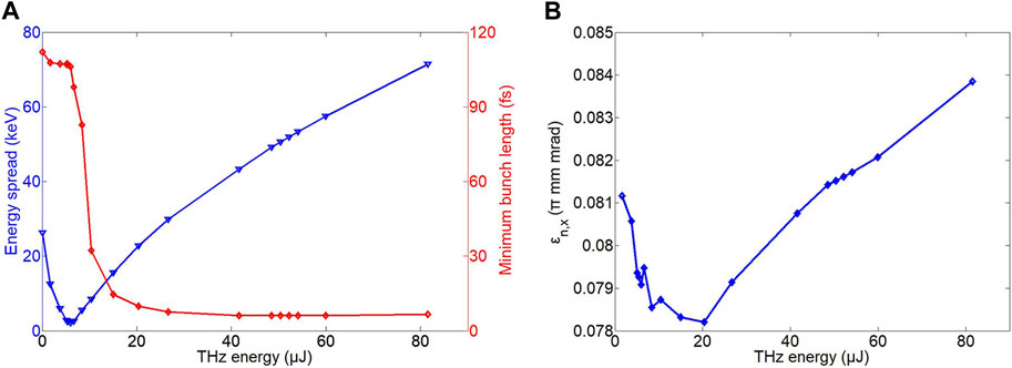
FIGURE 10. Evolution of (A) energy spread and minimum bunch length; (B) normalized transverse emittance as a function of the THz energy of the DLW compressor.
All the THz waves and photo-electrons are produced from the same seeding laser, and the phase jitter induced by the optical path is negligible. However, the energy jitter of the power system still has a strong impact on the beam parameters. Figure 11 shows the electron bunch energy and the time of arrival (TOA) at the entrance of the main linac under different THz energies. The energy jitter of the power system changes the injection energy and acceleration phase of the electron, and the compressor between the gun and the linac can significantly suppress these parameter jitters.
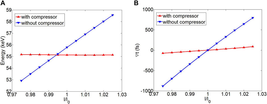
FIGURE 11. Energy (A) and TOA (B) at the entrance of the main linac under different THz energies.
The injection phase, the injection energy, and the THz energy jitter of the main linac lead to a significant fluctuation in beam qualities, as shown in Figure 12. The beam parameters change more gently under a THz energy jitter regime of ±1.5% and significantly deviate from the design value if the THz energy jitter changes above 1.5%.
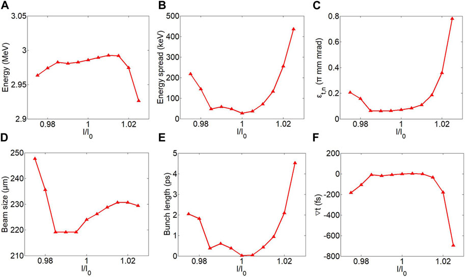
FIGURE 12. Output parameters of the injector under different THz energies. (A) Mean energy; (B) root-mean-square energy spread; (C) normalized transverse emittance; (D) root-mean-square bunch size; (E) root-mean-square bunch length; and (F) divergence of the TOA.
The jitter of the injector reduces the beam shaping quality of the THz electron source, as shown in Figure 13. The optimal bunch length and the minimum energy spread increase from the original value, and a stronger deviation appeals on the high-energy side. The divergence of the TOA is strongly suppressed by the DLW compressor.
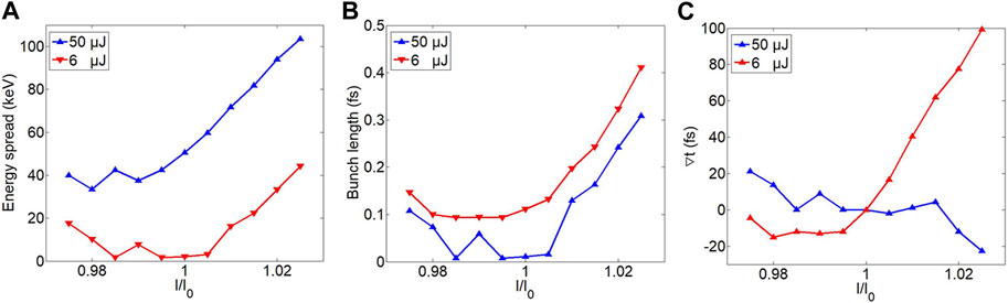
FIGURE 13. Output parameters of the beam shaping line under different THz energies. (A) Root-mean-square energy spread, (B) root-mean-square bunch length, and (C) divergence of the TOA.
To show the potential of the developed THz-driven electron source, we carry out UED simulations based on the produced electron beams using a similar code as in [31]. The DLW compressor works with 50 μJ THz energy to obtain a minimum relative energy spread of 0.08% since we are going to simulate a static UED pattern. A 312-nm-thick aluminum foil is located at z = 350 mm as the diffraction sample. By configuring the THz accelerator, a 2 fC, 3 MeV, 106.3 fs electron bunch is generated in front of the Al sample, with an RMS divergence of 23 μrad and a transverse bunch size of 200 μm. The electron screen is located 0.5 m downstream the sample. Figure 14A shows the simulated diffraction pattern. Figure 14B shows the scattering intensity as a function of the momentum transfer
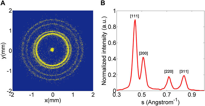
FIGURE 14. Simulated diffraction pattern (A) and the corresponding scattering intensity (B).
The project of this compact all-optical THz-driven electron source was first proposed in 2021 [22] based on our previous works on cascaded THz-driven acceleration [16], THz-based beam diagnostics [23], frequency-tunable single-cycle or multi-cycle optical THz sources [24], and THz streaking method. We have completed the technical design and are moving to the preliminary experimental demonstration of the key components. A prototype THz-driven electron gun has been fabricated and is currently under testing. Figure 15 shows the assembly of the THz gun and the experimental setup of the beam test. Fabrication of the tapered DLW and PMSs is on the schedule and the Joule-level multi-cycle THz source is under development. More comprehensive results will be reported in future works.
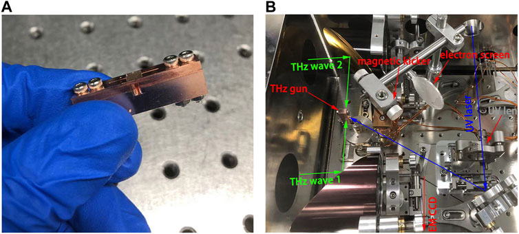
FIGURE 15. (A) Assembly of the THz gun and (B) experimental setup of the beam test.
We have proposed a compact all-optical THz-driven electron source at Tsinghua University. The THz-driven electron gun, tapered DLW linac, focusing PMSs, and THz-driven bunch compressors have been included in the physical design. Dynamic optimizations of the accelerator have produced 19 fC electron beams at 3 MeV, with a normalized transverse emittance of 0.079 π.mm.mrad. A minimum relative energy spread of 0.04% or a minimum RMS bunch length of 6.1 fs can be achieved by adjusting the beam shaping line. Sensitivity analysis shows that the THz-driven electron source can effectively work under a 1.5% energy jitter of the power system. A high-quality diffraction pattern has been simulated, showing the great potential of the designed THz-driven electron source for achieving high-quality MeV UED applications. We are currently working on the preliminary experimental demonstration of the prototype THz-driven electron gun and other beamline components. More comprehensive results will be reported in future works.
The original contributions presented in the study are included in the article/Supplementary Material, further inquiries can be directed to the corresponding author.
HX: conceptualization, data curation, formal analysis, investigation, methodology, software, and writing–original draft. RL: conceptualization, supervision, and writing–review and editing. LY: conceptualization, methodology, and writing–review and editing. YD: conceptualization, supervision, and writing–review and editing. QT: conceptualization, methodology, and writing–review and editing. WH: conceptualization, funding acquisition, project administration, supervision, and writing–review and editing. CT: conceptualization, supervision, and writing–review and editing.
The author(s) declare that financial support was received for the research, authorship, and/or publication of this article. This research was supported by the National Natural Science Foundation of China (NSFC Grant No. 12035010).
The authors thank Prof. Yutong Li, Prof. Jinglong Ma, and Baolong Zhang, a Ph.D student, from the Institute of Physics, Chinese Academy of Sciences, and Prof. Xiaojun Wu from Beihang University for their help in building the experimental platform for the beam test of the THz-driven electron gun.
The authors declare that the research was conducted in the absence of any commercial or financial relationships that could be construed as a potential conflict of interest.
All claims expressed in this article are solely those of the authors and do not necessarily represent those of their affiliated organizations, or those of the publisher, the editors, and the reviewers. Any product that may be evaluated in this article, or claim that may be made by its manufacturer, is not guaranteed or endorsed by the publisher.
1. Wang JW, Loew GA. Rf breakdown studies in copper electron linac structures. In: Proceedings of the 1989 IEEE Particle Accelerator Conference, 'Accelerator Science and Technology; March 1989; Chicago, IL, USA. IEEE (1989).
2. Dal Forno M, Dolgashev V, Bowden G, Clarke C, Hogan M, McCormick D, et al. RF breakdown tests of mm-wave metallic accelerating structures. Phys Rev Acc Beams (2016) 19(1):011301. doi:10.1103/physrevaccelbeams.19.011301
3. Wu X, Shi J, Chen H, Shao J, Abe T, Higo T, et al. High-gradient breakdown studies of an X-band Compact Linear Collider prototype structure. Phys Rev Acc Beams (2017) 20(5):052001. doi:10.1103/physrevaccelbeams.20.052001
4. Huang WR, Fallahi A, Wu X, Cankaya H, Calendron AL, Ravi K, et al. Terahertz-driven, all-optical electron gun. Optica (2016) 3(11):1209–12. doi:10.1364/optica.3.001209
5. Nanni EA, Huang WR, Hong KH, Ravi K, Fallahi A, Moriena G, et al. Terahertz-driven linear electron acceleration. Nat Commun (2015) 6(1):8486–8. doi:10.1038/ncomms9486
6. Zhang D, Fallahi A, Hemmer M, Wu X, Fakhari M, Hua Y, et al. Segmented terahertz electron accelerator and manipulator (STEAM). Nat Photon (2018) 12(6):336–42. doi:10.1038/s41566-018-0138-z
7. Peralta EA, Soong K, England RJ, Colby ER, Wu Z, Montazeri B, et al. Demonstration of electron acceleration in a laser-driven dielectric microstructure. Nature (2013) 503(7474):91–4. doi:10.1038/nature12664
8. England RJ, Noble RJ, Bane K, Dowell DH, Ng CK, Spencer JE, et al. Dielectric laser accelerators. Rev Mod Phys (2014) 86(4):1337–89. doi:10.1103/revmodphys.86.1337
9. Breuer J, Peter H. Laser-based acceleration of nonrelativistic electrons at a dielectric structure. Phys Rev Lett (2013) 111(13):134803. doi:10.1103/physrevlett.111.134803
10. Tajima T, Dawson JM. Laser electron accelerator. Phys Rev Lett (1979) 43(4):267–70. doi:10.1103/physrevlett.43.267
11. Chen P, Dawson JM, Huff RW, Katsouleas T. Acceleration of electrons by the interaction of a bunched electron beam with a plasma. Phys Rev Lett (1985) 54(7):1537. doi:10.1103/physrevlett.55.1537
12. Leemans WP, Nagler B, Gonsalves AJ, Tóth C, Nakamura K, Geddes CGR, et al. GeV electron beams from a centimetre-scale accelerator. Nat Phys (2006) 2(10):696–9. doi:10.1038/nphys418
13. Huang WR, Nanni EA, Ravi K, Hong KH, Fallahi A, Wong LJ, et al. Toward a terahertz-driven electron gun. Scientific Rep (2015) 5(1):14899–8. doi:10.1038/srep14899
14. Hibberd MT, Healy AL, Lake DS, Georgiadis V, Smith EJH, Finlay OJ, et al. Acceleration of relativistic beams using laser-generated terahertz pulses. Nat Photon (2020) 14(12):755–9. doi:10.1038/s41566-020-0674-1
15. Zhang D, Fakhari M, Cankaya H, Calendron AL, Matlis NH, Kärtner FX. Cascaded multicycle terahertz-driven ultrafast electron acceleration and manipulation. Phys Rev X (2020) 10(1):011067. doi:10.1103/physrevx.10.011067
16. Xu H, Yan L, Du Y, Huang W, Tian Q, Li R, et al. Cascaded high-gradient terahertz-driven acceleration of relativistic electron beams. Nat Photon (2021) 15(6):426–30. doi:10.1038/s41566-021-00779-x
17. Tang H, Zhao L, Zhu P, Zou X, Qi J, Cheng Y, et al. Stable and scalable multistage terahertz-driven particle accelerator. Phys Rev Lett (2021) 127(7):074801. doi:10.1103/physrevlett.127.074801
18. Zhao L, Wang Z, Lu C, Wang R, Hu C, Wang P, et al. Terahertz streaking of few-femtosecond relativistic electron beams. Phys Rev X (2018) 8(2):021061. doi:10.1103/physrevx.8.021061
19. Li RK, Hoffmann M, Nanni E, Glenzer S, Kozina M, Lindenberg A, et al. Terahertz-based subfemtosecond metrology of relativistic electron beams. Phys Rev Acc Beams (2019) 22(1):012803. doi:10.1103/physrevaccelbeams.22.012803
20. Zhao L, Tang H, Lu C, Jiang T, Zhu P, Hu L, et al. Femtosecond relativistic electron beam with reduced timing jitter from THz driven beam compression. Phys Rev Lett (2020) 124(5):054802. doi:10.1103/physrevlett.124.054802
21. Snively EC, Othman M, Kozina M, Ofori-Okai B, Weathersby S, Park S, et al. Femtosecond compression dynamics and timing jitter suppression in a THz-driven electron bunch compressor. Phys Rev Lett (2020) 124(5):054801. doi:10.1103/physrevlett.124.054801
22. Xu H., Li R., Yan L., Du Y., Tang C., Huang W., et al. A 3 MeV all optical terahertz-driven electron source at Tsinghua University (2021).
23. Tian Q, Du Y, Xu H, Liang Y, Wang Y, Tan Y, et al. Single-shot spatial-temporal electric field measurement of intense terahertz pulses from coherent transition radiation. Phys Rev Acc Beams (2020) 23(10):102802. doi:10.1103/physrevaccelbeams.23.102802
24. Tian Q, Xu H, Wang Y, Liang Y, Tan Y, Ning X, et al. Efficient generation of a high-field terahertz pulse train in bulk lithium niobate crystals by optical rectification. Opt Express (2021) 29(6):9624–34. doi:10.1364/oe.419709
25. Zhang B, Ma Z, Ma J, Wu X, Ouyang C, Kong D, et al. 1.4-mJ high energy terahertz radiation from lithium niobates. Laser Photon Rev (2021) 15(3):2000295. doi:10.1002/lpor.202000295
26. Jolly SW, Matlis NH, Ahr F, Leroux V, Eichner T, Calendron AL, et al. Spectral phase control of interfering chirped pulses for high-energy narrowband terahertz generation. Nat Commun (2019) 10(1):2591–8. doi:10.1038/s41467-019-10657-4
27. Dassault Systèmes. Cst studio suite electromagnetic field simulation software (2022). Available at: www.cst.com.
28. Pereverzev GV, Yushmanov PN. ASTRA. Automated system for transport analysis in a tokamak (2002).
29. Lemery F, Floettmann K, Piot P, Kärtner F, Aßmann R. Synchronous acceleration with tapered dielectric-lined waveguides. Phys Rev Acc Beams (2018) 21(5):051302. doi:10.1103/physrevaccelbeams.21.051302
30. Gehrke T. Design of permanent magnetic solenoids for REGAE. Master thesis. Hamburg, Germany: Deutsches Elektronen-Synchrotron (2013). No. DESY-THESIS--2013-046.
Keywords: terahertz-driven acceleration, terahertz-driven beam manipulation, terahertz-driven beam diagnostics, terahertz-driven electron guns, beam dynamics
Citation: Xu H, Li R, Yan L, Du Y, Tian Q, Huang W and Tang C (2023) Towards a compact all-optical terahertz-driven electron source. Front. Phys. 11:1292194. doi: 10.3389/fphy.2023.1292194
Received: 11 September 2023; Accepted: 23 October 2023;
Published: 06 November 2023.
Edited by:
Weihao Liu, Nanjing University of Aeronautics and Astronautics, ChinaReviewed by:
Giuseppe Torrisi, Laboratori Nazionali Del Sud (INFN), ItalyCopyright © 2023 Xu, Li, Yan, Du, Tian, Huang and Tang. This is an open-access article distributed under the terms of the Creative Commons Attribution License (CC BY). The use, distribution or reproduction in other forums is permitted, provided the original author(s) and the copyright owner(s) are credited and that the original publication in this journal is cited, in accordance with accepted academic practice. No use, distribution or reproduction is permitted which does not comply with these terms.
*Correspondence: Wenhui Huang, aHVhbmd3aEBtYWlsLnRzaW5naHVhLmVkdS5jbg==
Disclaimer: All claims expressed in this article are solely those of the authors and do not necessarily represent those of their affiliated organizations, or those of the publisher, the editors and the reviewers. Any product that may be evaluated in this article or claim that may be made by its manufacturer is not guaranteed or endorsed by the publisher.
Research integrity at Frontiers
Learn more about the work of our research integrity team to safeguard the quality of each article we publish.