 Jingxia Qiang
 Feng Xu
 Ling Yang
 Shui Liu
- School of Electronic and Optical Engineering, Nanjing University of Posts and Telecommunications (NJUPT), Nanjing, Jiangsu, China
A novel structure of slot antenna with high gain and compact size for millimeter-wave (mmW) applications is proposed. This is the first attempt to apply slow-wave substrate integrated waveguide (SW-ESIW) to the field of antennas and their arrays. Two slot antenna arrays were designed, fabricated and measured. The measured results are in agreement with the simulation. The removal of dielectric substrate improves the radiation gain. At the same time, the slow wave effect, by means of physical separation of electric and magnetic fields, decreases both the lateral and longitudinal dimensions of the antenna. The SW-ESIW slot antenna can achieve miniaturization while retaining the advantages of high gain of ESIW. The 1 × 4-slot array shows a measured −10 dB bandwidth of 16% (30.5–35.8 GHz) with a measured maximum gain of 11.69 dB. The 4 × 4-slot array achieves a measured −10 dB bandwidth of 7.6% from 31.6 to 34.1 GHz with a measured peak gain of 18.75 dB. In addition, during the operating band, the radiation pattern is stable. Compared with the previously structures, the proposed SW-ESIW antenna structure has a better trade-off between gain and footprint. It can be flexibly adjusted to adapt to different requirements. These performances ensure that the antenna array based on the proposed structure is a promising candidate for millimeter-wave wireless applications including the fifth-generation mobile communications.
1 Introduction
With the increasing demand of the mass market for electronics and communication applications, millimeter-wave (mmW) technology, as one of the most promising solutions that help provide high-data rate transmission in the fifth generation (5G) and beyond wireless communications, has become a significant research topic. Waveguide slot arrays [1–13] are strong candidates for the front-end millimeter-wave waveguide systems, such as radar systems, SATCOM, and 5G wireless communications, due to the advantages of low cost, high efficiency, and high performance.
In recent years, the substrate-integrated waveguide (SIW) [14–23] has been extensively analyzed and experimentally studied due to higher-quality factors and better integration compared with other low-profile microstrip and coplanar structures. The high-gain slot element can simplify the antenna array design efficiently. Therefore, how to enhance the gain of the SIW slot antenna has attracted a significant amount of attention. The usual approach to designing a high-gain slot antenna is to load a parasitic element covering a conventional slot [6–8, 24, 25] or construct a sub-array configuration [26–28]. However, the gain enhancement of the dielectric-filled substrate-integrated waveguide (DFSIW) slot antenna is limited due to the presence of the dielectric substrate.
The gap waveguide (GW) technology can increase gain appropriately due to its relatively low loss. The working principle is to prevent the lateral propagation of the electromagnetic wave by using a high-impedance surface on both sides. Therefore, it has the weakness of being large and heavy. Moreover, several new type substrate-integrated waveguides without the dielectric substrate, such as the air-filled substrate-integrated waveguide (AFSIW) [29] and the empty substrate-integrated waveguide (ESIW) [30], are used to improve the gain of slot antennas. Both the AFSIW and ESIW have lower insertion loss and better power-handling capabilities compared to DFSIW, which makes it promising for designing high-efficiency slot arrays. Parment F et al. [31] proposed an AFSIW 1 × 4-slot array antenna based on the multilayer PCB process. At the same operating band of 30.5 GHz, the gain and efficiency of the AFSIW antenna are 3.5 dB and 1.6% higher than those of the DFSIW, respectively. In [32], a 1 × 10-slotted ESIW antenna for a multiple-input multiple-output (MIMO) radar sensor was introduced. It achieved a measured gain of 15 dB in the target operating band (16–16.5 GHz). To investigate the potential of the ESIW in designing slot arrays with more elements and higher radiation gain, in [33], two slot antenna arrays were designed. The 1 × 6-slot antenna achieved a maximum gain of 15.5 dB at 38 GHz, and the 6 × 8-slot antenna showed a maximum gain of 24 dB at 39 GHz. However, because the air cavity requires a rectangular hole to be hollowed out in the middle substrate, the structure should be at least three layers and the physical dimension is larger, which greatly confines their applications. Therefore, for both the GW and ESIW, how to realize the planar slot antenna array with high gain and -compact structure is still a challenging task.
We successfully achieved the proposed novel waveguide, the slow-wave empty substrate-integrated waveguide (SW-ESIW) in [34]. The structure combined the advantages of SW-SIW and ESIW technologies and has proven to be useful in filters with miniaturization and high-quality factors. However, its performance in the field of antennas remains to be further studied.
In this paper, the SW-ESIW structure is proposed to realize the application of the antenna for the first time. A new-type method to balance the radiation gain and physical dimension of the slot antenna is proposed and studied with the objective of offering a high-performance SIW slot antenna alternative. The structure is implemented using multilayer PCB technology, utilizing air cavities to improve antenna gain and utilizing the slow-wave structure to balance the size of the antenna. In addition, the operating frequency band covers the millimeter-wave band. This structure improves the SW-ESIW technology system and lays a foundation for the subsequent design of more complex antennas based on the SW-ESIW.
This paper is organized as follows. In Section 2, the novel antenna topology is introduced. Its mechanism of high gain and miniaturization is analyzed, and the results are compared with other SIW structures. In order to demonstrate the possibility of SW-ESIW slot array development, Section 3 presents the design and experimental validation of a 1 × 4-slot array and a 4 × 4-slot array. A comparison with the state of the art is also discussed to highlight the performance of the antenna developed in this work. Finally, Section 4 provides the conclusion of the work and prospects for future work.
2 Antenna element design
2.1 Topology
A cross sectional view of the proposed SW-ESIW structure is shown in Figure 1A. It consists of a slow-wave substrate and empty SIW transmission structure, with a slot. The structure bases on a triple-layer substrate, and the layering diagram is shown in Figure 1B. Substrate 1 implements the top conducting boundary for the middle air layer (substrate 2). Lateral via-holes in substrate 3 define the cavity size as a conventional SIW cavity, and internal via-holes are periodically arranged among them to form a high slow-wave effect.

FIGURE 1. The proposed SW-ESIW. (A) Cross-sectional view; (B) explosive view.
In the proposed triple-layer structure, sub 2 and sub 3 are designed for the same substrate. The total height is h = h2 + h3 = 0.762 mm, and the copper thickness is 0.017 mm. In order to be more cost effective and compact, low-cost material such as FR-4 can be manufactured for sub 1, which provides an upper metallic wall with a radiation slot for the air cavity. In sub 3, the period of internal via-holes is s1 in both longitude and lateral directions. The diameters of internal and lateral via-holes are d1 and d2, respectively. The width and length of the slot in sub 1 are wslot and lslot, respectively.
To integrate the structure into a printed circuit, it is necessary to design a high-quality transition from a microstrip line to SW-ESIW. The transition can be regarded as a two-stage mode converter. In the first stage, the microstrip mode is converted into the fundamental mode of a waveguide partially filled with dielectric, where a metal iris is opened in the back wall to increase the matching of the two modes. In the second stage, the fundamental mode of the partially filled waveguide is converted to that of the final slow-wave empty waveguide. To better achieve a high-quality transition, an exponential taper, with the length lt and the rounded end, is fabricated so that the dielectric filling of the initial waveguide is progressively decreased according to the exponential law until it effectively disappears. The details are shown in Figure 2.
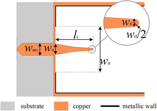
FIGURE 2. Details of transition.
2.2 EM field
In order to illustrate the principle of the slow-wave effect in the proposed structure, full-wave electromagnetic simulations were carried out using high-frequency electromagnetic field simulation software, High Frequency Structure Simulator (HFSS).
Figures 3A, B show the magnitude of the electric and magnetic field in the proposed SW-ESIW cavity. Similar to other slow-wave structures, the internal metallized via-holes in the substrate (sub 3) physically concentrate the EM field and increase the inductive effect. Figure 3 shows that the electric field is mainly concentrated in the air region, as the conventional SW-SIW structure does. On the contrary, the magnetic field continues to diffuse throughout the entire air substrate (sub 2) and distributes around the via-holes in sub 3. Relative to the conventional SW-SIW cavity, the proposed SW-ESIW cavity, which emptied a rectangular hole in sub 2, still shows a clear feature of the slow-wave effect: an effective separation of the electric and magnetic field.
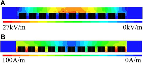
FIGURE 3. Cross-sectional view of the proposed SW-ESIW in the middle of a transversal via-hole section. (A) Electric magnitude. (B) Magnetic field magnitude.
2.3 Parametric study
Based on the analysis of slow wave [35], both the cutoff frequency and the phase velocity decrease with the presence of internal metal via-holes. The same is true of the SW-ESIW. Figure 4A shows the dispersion diagram of the slow-wave structure unit cell, which is calculated using the CST Studio Suite (CST) eigenmode solver. To further investigate the law of performance with the variation of parameters, parameter studies of different thicknesses of waveguide h and air cavity h2 are detailed as follow.
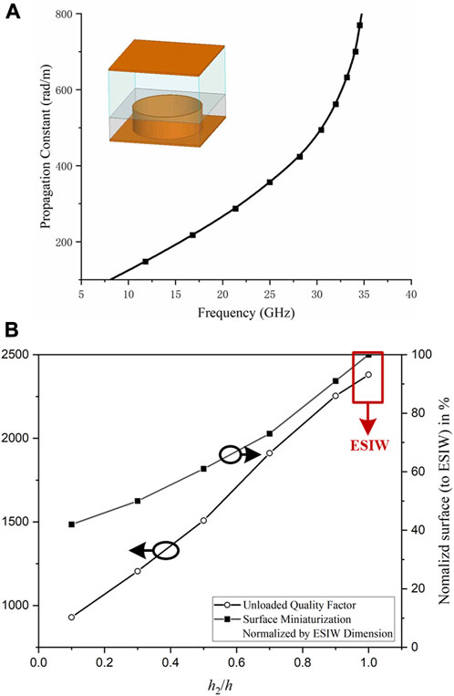
FIGURE 4. (A) Dispersion diagram of the SW-ESIW; (B) surface miniaturization (normalized by the ESIW cavity dimension) and unloaded quality factor of the SW-ESIW cavity versus the different values of the relative height (h2/h) of Sub 2 (h = 0.762 mm).
Figure 4B shows the influence of the thickness of the air cavity on surface miniaturization and the quality factor of the SW-ESIW structure. All of the simulations are based on Rogers 4350 (εr = 3.66, tanδ = 0.004) with a thickness of h = 0.762 mm. As shown in Figure 4B, the surface decreases with the diminution of the relative height h2/h because of the enhancement of the slow-wave effect. This is mainly due to the higher electric field accommodation in the top volume of the SW-ESIW structure. The higher the slow-wave effect is, the smaller the size of the air cavity and the higher the loss of the cavity. Hence, in order to achieve better performance, it is significant to deal with a trade-off between the compactness and quality factor. For example, when h2/h = 0.1 is selected, the equivalent size is small because of the strong slow-wave effect. However, as the cost of dimension, the quality factor is not high, which means the total efficiency is not high. When h2/h = 0.7 is selected, the quality factor and radiation gain are better. On the other hand, there is less advantage in miniaturization. Therefore, the different ratios of h2/h are flexible to suit different requirements between compactness and quality factors. Considering the trade-off of miniaturization and higher radiation gain, the relative height of h2/h = 2/3 is considered in this cavity.
On the basis of the blind via-holes matrix, the effective relative dielectric constant
where h2 and h3 are the heights of sub 2 and sub 3, respectively. εr3 is the relative dielectric constant of sub 1, which is set to 3.66 of Rogers 4350. On account of the air layer sub 2, εr2 is the assigned value of 1. Considering the total height h is constant, the effective relative dielectric constant εr_eff is inversely proportional to the height h2. Hence, the operating frequency f0_SW-ESIW of the SW-ESIW cavity can be defined by the dielectric constant εr_eff as follows:
With Eq. 2, a resonance frequency f0_SW-ESIW of 13 GHz is obtained for the fundamental mode TE110, with the substrate layer heights being h2 = 0.508 mm and h3 = 0.254 mm.
2.4 Result
In order to better compare the advantages of the SW-ESIW structure in the antennas, the full-wave simulation of single-cavity slot antennas with different technologies is carried out using HFSS. The optimal values of the basic design parameter of the proposed SW-ESIW single-cavity antenna are shown in Table 1. Table 2 shows the performance comparison of three antennas based on the DFSIW, ESIW, and SW-ESIW. They all operate at 13 GHz, which means the operating wavelength is 23 mm. All the substrate are Rogers RO4350 with a relative dielectric constant εr = 3.66 and dielectric loss tangent tanδ = 0.004. The cavity thickness of Antenna I and II is h = 0.762 mm. It is evident to observe that the introduction of the air cavity can effectively increase the radiation gain at the operating frequency, at the expense of its dimension. Compared with Antenna I, Antenna II and III obtained an increase gain of 1.5 and 1.3 dB, respectively, due to the addition of air cavities. However, by introducing the slow-wave effect, Antenna III achieves a significant size advantage (30.5% less than that of Antenna II) with only a very small loss of gain (0.2 dB and 3% lower than that of Antenna II). The promising results obtained strongly suggest that the SW-ESIW structure can achieve miniaturization, while retaining the advantages of high gain of ESIW, and has a widespread application prospect in the antenna design.
TABLE 1. Proposed slot single-cavity antenna parameter values.
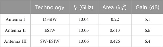
TABLE 2. Comparison of slot single-cavity antennas with different technologies.
3 Antenna array design
Section 2 proved that the SW-ESIW single-cavity antenna has a significant size advantage in the Ku band and greatly improves the gain of the antenna. On this basis, we further designed two antenna arrays in the Ka band, which proved that the structure can also perform well in the millimeter-wave band.
3.1 Design
In order to investigate the ability to construct large-scale arrays using the SW-ESIW, a single SW-ESIW with four slots was first investigated to form a 1 × 4-slot array. Then, based on the 1 × 4-slot array, a 4 × 4-slot array is proposed.
An exploding view of a 1 × 4-slot antenna array is shown in Figure 5. The proposed antenna has three layers from top to bottom. Layer 1 is used to create the radiation slots. Layer 2 is used to fabricate the air cavity. Layer 3 is used to create the slow-wave effect. Parts of dielectric are removed from these structures, and the inner walls are then metallized.
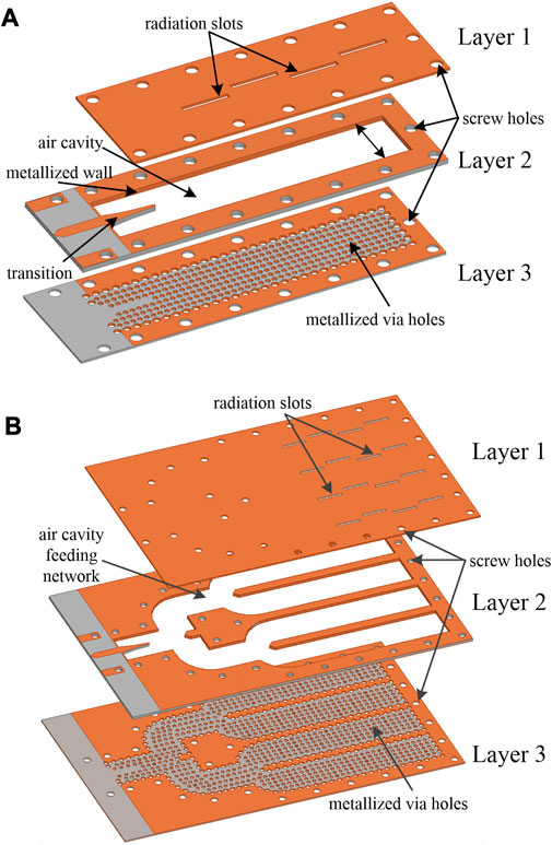
FIGURE 5. Layout of the proposed two SW-ESIW antenna arrays. (A) 1 × 4 slot array and (B) 4 × 4 slot array.
Based on the 1 × 4-slot antenna array, a 4 × 4-slot antenna array is built. Figure 6 presents the feeding network of the 4 × 4-array, which can work well with a low-fabrication precision.
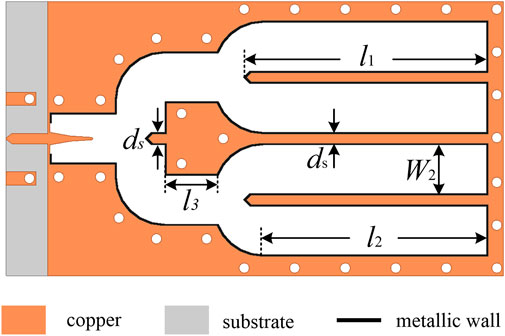
FIGURE 6. Top view of sub 2 of the 4 × 4-slot array.
In order to better compare their performances, two contrast antennas based on ESIW technology are designed and fabricated at the same time. Contrast I is a 1 × 4-ESIW slot antenna, whereas Contrast II is a 4 × 4-array.
3.2 Fabrication
Photographs of the proposed two slot antenna arrays are shown in Figure 7. The total dimension of the 1 × 4-slot antenna array is 35.4 mm × 10 mm, while the total dimension of the 4 × 4-slot array is 57.7 mm × 33.5 mm. First, three substrates are processed separately. All metal via-holes, including internal and lateral via-holes in layer 3, are perforated in the same process as those of the SIW. Both the radiation slots in layer 1 and the air cavity in layer 2 are hollowed out and the surrounding is metallized. Figure 7A shows the details of the metallized wall of layer 2. Second, several holes that are slightly larger than the screw are placed uniformly around the antenna arrays. Finally, three layers are held together by screws.
FIGURE 7. (A) Metallization of the lateral wall of sub 2; (B) measured photograph of the 4 × 4-slot antenna array; (C) three substrates of the 1 × 4-slot SW-ESIW array antenna before assembling; (D) three substrates of the 4 × 4-slot SW-ESIW array antenna before assembling.
3.3 Measurements
All the simulations were performed using HFSS software. The final optimal parameters of the SW-ESIW slot antenna arrays obtained by optimization are shown in Table 3. The performance of impedance matching was measured using the Keysight vector analyzer N5247A. All the far-field characteristics were measured in a microwave anechoic room, as shown in Figure 7B.
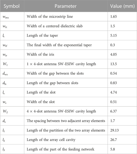
TABLE 3. Proposed slot antenna array parameter values.
Figures 8, 9 show the simulation and measured S11 and the realized gains of the proposed antenna arrays. The 1 × 4-slot array achieves a simulated maximum realized gain of 11.93 dB at 35 GHz with a gain bandwidth of 10 dB from 30.6 to 35.8 GHz. The measured bandwidth of 10 dB of the 1 × 4-slot array is 16% (30.5–35.8 GHz), which is slightly wider than the simulation result. The measured maximum realized gain is 11.69 dB at 32 GHz, which is slightly less than the simulation value due to mismachining tolerance.
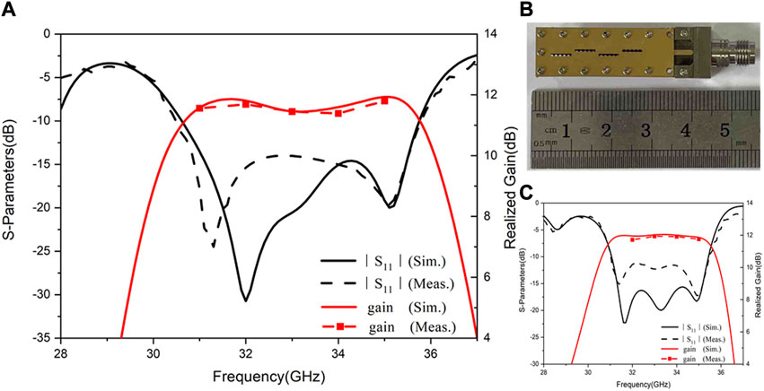
FIGURE 8. (A) Measured and simulated |S11| and realized gains for the proposed 1 × 4-slot SW-ESIW array antenna; (B) fabricated 1 × 4-slot SW-ESIW array antenna; and (C) performance of the S-parameter and realized gain for the contrast I: 1 × 4-slot ESIW array antenna.
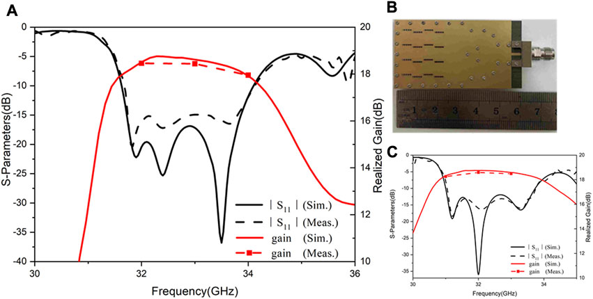
FIGURE 9. (A) Measured and simulated |S11| and realized gains for the proposed 4 × 4-slot SW-ESIW array antenna; (B) fabricated 4 × 4-slot SW-ESIW array antenna; and (C) performance of the S-parameter and realized gain for the contrast II: 4 × 4-slot ESIW array antenna.
For the proposed 4 × 4-slot antenna array, the coupling between each line was reduced by optimizing the parameters, resulting in a simulated bandwidth of 10 dB from 31.6 to 34.1 GHz. The measured bandwidth of 10 dB is 7.6% (31.6–34.1 GHz), which is consistent with the simulation result. The proposed 4 × 4-slot antenna array realizes a maximum realized gain of 18.75 dB at 32.5 GHz, and the gain bandwidth of 1 dB is 31.7–34 GHz.
The aperture area of the 1 × 4 and 4 × 4 arrays is defined as 5.8 × 22.4 mm2 and 28.3 × 20.3 mm2, respectively. The aperture efficiency εap can be calculated as follows:
where A and G are the aperture and gain of the antenna, respectively [36]. At the center frequency, the aperture efficiencies of 1 × 4 and 4 × 4 arrays are 77.7% and 86.5%, respectively.
Both simulated and measured co-polarization and cross-polarization radiation patterns for the E-plane (xoz) and the H-plane (xoy) at 31, 32, 33, 34, and 35 GHz of the proposed 1 × 4-slot antenna array are shown in Figure 10. Similarly, Figure 11 illustrates the performances at 32, 33, and 34 GHz of the proposed 4 × 4-slot antenna array. Stable radiation patterns can be observed at the operating band. The experimental results agree well with the simulated radiation patterns in both the E-plane and the H-plane for the proposed two antenna arrays. The measured co-polarization ratio is approximately 10 dB higher than the simulation result observed in the E-plane since the antenna was not placed completely vertically in the process of the experiment. According to the post-simulation results, it is estimated to be titled 2°–3° from the y-axis measured. This has little effect on the cross-polarization of the H-plane. Moreover, the measured cross-polarization is in a good agreement with the simulated results in the H-plane.
FIGURE 10. Far-field simulated and measured radiation patterns at 31, 32, 33, 34, and 35 GHz for the E-plane and the H-plane of the 1 × 4-slot array.
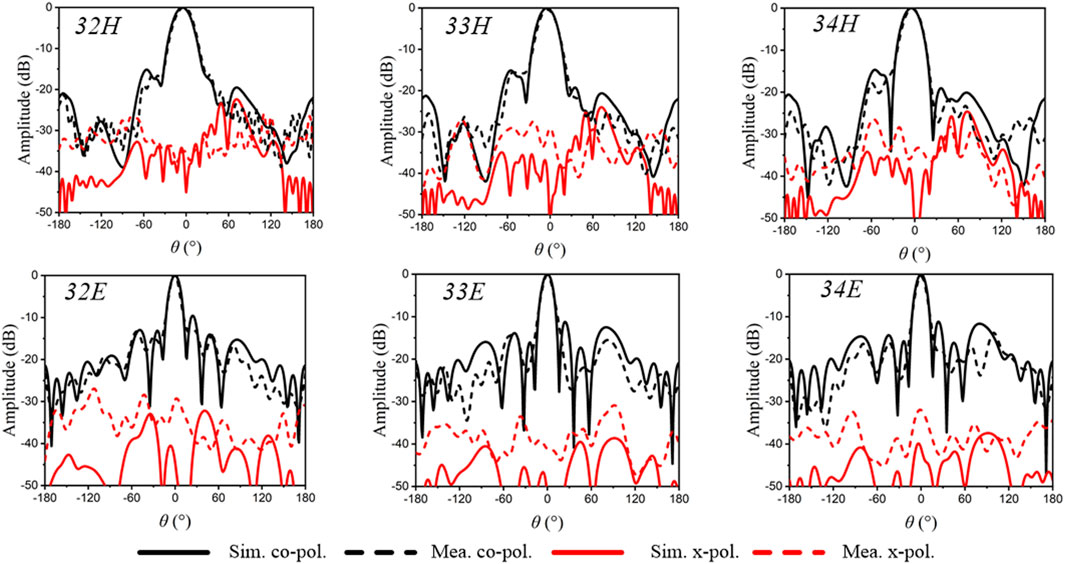
FIGURE 11. Far-field simulated and measured radiation patterns at 32, 33, and 34 GHz for the E-plane and the H-plane of the 4 × 4-slot array.
3.4 Comparison
In order to compare the performance more directly, two contrast slot antenna arrays are simulated and fabricated simultaneously. Figures 8C, 9C show the performance of the S-parameter and realized gain for the contrast 1 × 4-slot and 4 × 4-slot ESIW array antenna, respectively. Compared with contrast I, the proposed 1 × 4-slot antenna achieves an improved dimension reduction of 29.4% with a realized gain reduction of 0.23 dB and 1.9%. Similarly, compared with contrast II, the proposed 4 × 4-slot antenna is reduced by 28.5% in size and only 0.23 dB and 1.2% in radiation gain.
Table 4 summarizes the comparison of the proposed and some previous slot-type antenna arrays. Compared with DFSIW technology, both ESIW and SW-ESIW technologies have significant gain improvements. At the expense of this, the structure is more multilayered and larger in dimension. However, by introducing the slow-wave effect, the SW-ESIW slot antenna array can achieve a relative reduction in size, while greatly improving the radiation gain. Relative to the ESIW antenna, the proposed SW-ESIW antennas achieve a miniaturization of greater than 28.5% with a small effect in gain, while maintaining a three-layer structure.
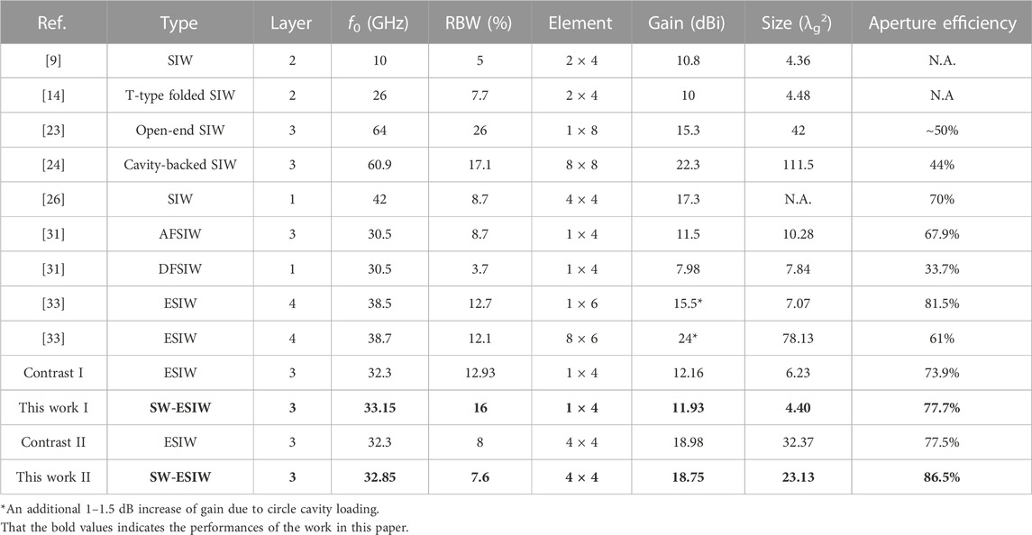
TABLE 4. Comparisons between the previous literature and this work.
4 Conclusion
A novel approach to guarantee the high performance and miniaturization of slot antennas is proposed in the SW-ESIW technological platform for the first time. The SW-ESIW structure is used to extend the frequency band to the millimeter-wave band for the first time, which provides a new design idea for the high-performance slot antenna in the millimeter-wave band. The proposed SW-ESIW antenna with a single cavity can achieve a significant size advantage (30.5% less than that of the ESIW slot antenna) with only a very small loss of gain (0.2 dB and 3% lower than that of the ESIW slot antenna) compared with the same antenna based on the ESIW, while maintaining the ESIW triple-layer structure. To further validate the proposed structure, two millimeter-wave slot antenna arrays are designed for applications. A 1 × 4-slot array and a 4 × 4-slot antenna array are fabricated and measured. The measurements demonstrate that the SW-ESIW slot antenna arrays achieved a higher realized gain (measured 4 dB higher than that of the DFSIW slot array) and a relatively smaller lateral and longitudinal dimensions (at least reduced by 28.5% for the ESIW slot array). It skillfully combines the advantages of low loss caused by the removal and miniaturization of dielectric caused by the slow-wave effect, which, consequently, shows the characteristics of low cost, easy integration, and high gain. Moreover, by adjusting the height ratio between the air cavity and the slow-wave layer, the SW-ESIW antenna can also make a flexible trade-off between smaller size and higher gain to meet the various requirements in wireless communications. Since the SW-ESIW has proven to be a good candidate for transmission and filters, this antenna concept enhances the SW-ESIW’s ability to deploy systems on substrate (SoS) with optimal performance, size, and cost trade-offs.
Data availability statement
The raw data supporting the conclusion of this article will be made available by the authors, without undue reservation.
Author contributions
JQ: writing-original draft and writing-review and editing. FX: writing-review and editing. LY: writing-review and editing. SL: writing-review and editing. JZ: writing-review and editing.
Funding
The authors declare that financial support was received for the research, authorship, and/or publication of this article. This work was supported by the Specially Appointed Professor Program Foundation of Jiangsu Province of China, the Natural Sciences and Engineering Research Council of Canada, the Innovation Team Program Foundation of Jiangsu Province of China, the Major Project Fund of Natural Science Research in Colleges, and Universities of Jiangsu Province under grant no. 16KJA510003.
Conflict of interest
The authors declare that the research was conducted in the absence of any commercial or financial relationships that could be construed as a potential conflict of interest.
Publisher’s note
All claims expressed in this article are solely those of the authors and do not necessarily represent those of their affiliated organizations, or those of the publisher, the editors, and the reviewers. Any product that may be evaluated in this article, or claim that may be made by its manufacturer, is not guaranteed or endorsed by the publisher.
References
1. Liao SW, Chen PY, Wu P, Shum KM, Xue Q. Substrateintegrated waveguide-based 60-GHz resonant slotted waveguide arrays with wide impedance bandwidth and high gain. IEEE Trans Antennas Propag (2015) 63(7):2922–31. doi:10.1109/tap.2015.2423696
2. Wen Q, Wang BZ, Ding X. Wide-beam SIW-slot antenna for wide-angle scanning phased array. IEEE Antennas Wireless Propag Lett (2016) 15:1638–41. doi:10.1109/lawp.2016.2519938
3. Cheng YJ, Wang J, Liu XL. 94 GHz substrate integrated waveguide dual-circular-polarization shared-aperture parallel-plate long-slot array antenna with low sidelobe level. IEEE Trans Antennas Propag (2017) 65(11):5855–61. doi:10.1109/tap.2017.2754423
4. Liu B, Zhao R, Ma Y, Guo Z, Wei X, Xing W, et al. A 45$^\circ$ linearly polarized slot array antenna with substrate integrated coaxial line technique. IEEE Antennas Wireless Propag Lett (2018) 17(2):339–42. doi:10.1109/lawp.2018.2789585
5. Tekkouk K, Hirokawa J, Oogimoto K, Nagatsuma T, Seto H, Inoue Y, et al. Corporate-feed slotted waveguide array antenna in the 350-GHz band by silicon process. IEEE Trans Antennas Propag (2017) 65(1):217–25. doi:10.1109/tap.2016.2631132
6. Wu Y, Hao Z, Miao Z, Hong W, Hong J. A 140 GHz highefficiency slotted waveguide antenna using a low-loss Feeding network. IEEE Trans Antennas Propaga (2020) 19(1):94–8. doi:10.1109/lawp.2019.2954138
7. Jiang ZH, Wu Q, Brocker DE, Sieber PE, Werner DH. A low-profile high-gain substrate-integrated waveguide slot antenna enabled by an ultrathin anisotropic zero-index metamaterial coating. IEEE Trans Antennas Propaga (2014) 62(3):1173–84. doi:10.1109/tap.2013.2294354
8. Pandit S, Mohan A, Ray P. A low-profile high-gain substrateintegrated waveguide-slot antenna with suppressed cross polarization using metamaterial. IEEE Antennas Wireless Propag Lett (2017) 16:1614–7. doi:10.1109/lawp.2017.2654260
9. Wei J, Chen ZN, Qing X, Shi J, Xu J. Compact substrate integrated waveguide slot antenna array with low back lobe. IEEE Antennas Wireless Propag Lett (2013) 12:999–1002. doi:10.1109/lawp.2013.2277876
10. Vosoogh A, Kildal P, Vassilev V. Wideband and high-gain corporate-fed gap waveguide slot array antenna with ETSI class II radiation pattern in $V$ -band. IEEE Trans Antennas Propaga (2017) 65(4):1823–31. doi:10.1109/tap.2016.2634282
11. Caytan O, Lemey S, Agneessens S, Vande Ginste D, Demeester P, Loss C, et al. Half-mode substrate-integrated-waveguide cavitybacked slot antenna on cork substrate. IEEE Antennas Wireless Propag Lett (2015) 15:162–5. doi:10.1109/lawp.2015.2435891
12. Yang B, Yu Z, Dong Y, Zhou J, Hong W. Compact tapered slot antenna array for 5G millimeter-wave massive MIMO systems. IEEE Trans Antennas Propaga (2017) 65(12):6721–7. doi:10.1109/tap.2017.2700891
13. Yi X, Wong H. Wideband substrate integrated waveguide fed open slot antenna array. IEEE Access (2020) 8:74167–74. doi:10.1109/access.2020.2988053
14. Ding Y, Wu K. T-type folded substrate integrated waveguide (TFSIW) slot array antenna. IEEE Trans Antennas Propag (2010) 58(5):1792–5. doi:10.1109/tap.2010.2044349
15. Deslandes D, Wu K. Integrated microstrip and rectangular waveguide in planar form. IEEE Microw Wireless Compon Lett (2001) 11(2):68–70. doi:10.1109/7260.914305
16. Xu F, Zhang Y, Hong W, Wu K, Cui TJ. Finite-difference frequency-domain algorithm for modeling guided-wave properties of substrate integrated waveguide. IEEE Trans Microw Theor Techn. (2003) 51(11):2221–7. doi:10.1109/tmtt.2003.818935
17. Xu F, Wu K. Guided-wave and leakage characteristics of substrate integrated waveguide. IEEE Trans Microw Theor Techn. (2005) 53(1):66–73. doi:10.1109/tmtt.2004.839303
18. Xu F, Wu K, Zhang X. Periodic leaky-wave antenna for millimeter wave applications based on substrate integrated waveguide. IEEE Trans Antennas Propagation (2010) 58(2):340–7. doi:10.1109/tap.2009.2026593
19. Zhu J, Li S, Liao S, Yang Y, Zhu H. 60 GHz substrate-integrated-waveguide-fed patch antenna array with quadri-polarization. IEEE Trans Antennas Propagation (2018) 66(12):7406–11. doi:10.1109/tap.2018.2869255
20. Awida MH, Fathy AE. Design guidelines of substrate-integrated cavity backed patch antennas. Microw., Antennas Propag. (2012) 6(2):151–7. doi:10.1049/iet-map.2011.0376
21. Shen D, Ma C, Ren W, Zhang X, Ma Z, Qian R. A low-profile substrate-integrated-gap-waveguide-fed magnetoelectric dipole. IEEE Trans Antennas Propaga (2018) 17(8):1373–6. doi:10.1109/lawp.2018.2845848
22. Choubey PN, Hong W, Hao Z, Chen P, Duong T, Mei J. A wideband dual-mode SIW cavity-backed triangular-complimentarysplit-ring-slot (TCSRS) antenna. IEEE Trans Antennas Propaga (2016) 64(6):2541–5. doi:10.1109/tap.2016.2550036
23. Ruan X, Chan CH. An endfire circularly polarized complementary antenna array for 5G applications. IEEE Trans Antennas Propaga (2020) 68(1):266–74. doi:10.1109/tap.2019.2934888
24. Chen Z, Liu H, Yu J, Chen X. High gain, broadband and dual-polarized substrate integrated waveguide cavity-backed slot antenna array for 60 GHz band. IEEE Access (2018) 6:31012–22. doi:10.1109/access.2018.2845917
25. Sun G, Wong H. A planar millimeter-wave antenna array with a pillbox-distributed network. IEEE Trans Antennas Propaga (2020) 68(5):3664–72. doi:10.1109/tap.2020.2963931
26. Yang TY, Hong W, Zhang Y. Wideband millimeter-wave substrate integrated waveguide cavity-backed rectangular patch antenna. IEEE Antennas Wireless Propag Lett (2014) 13:205–8. doi:10.1109/lawp.2014.2300194
27. Han W, Yang F, Ouyang J, Yang P. Low-cost wideband and high-gain slotted cavity antenna using high-order modes for millimeterwave application. IEEE Trans Antennas Propaga (2015) 63(11):4624–31. doi:10.1109/tap.2015.2473658
28. Bayderkhani R, Forooraghi K, Abbasi-Arand B. Gain-enhanced SIW cavity-backed slot antenna with arbitrary levels of inclined polarization. IEEE Antennas Wireless Propag Lett (2015) 14:931–4. doi:10.1109/lawp.2014.2387015
29. Parment F, Ghiotto A, Vuong T -P, Duchamp J -M, Wu K. Air-filled substrate integrated waveguide for low-loss and high power-handling millimeter-wave substrate integrated circuits. IEEE Trans Microwave Theor Tech (2015) 63(4):1228–38. doi:10.1109/tmtt.2015.2408593
30. Belenguer A, Esteban H, Boria VE. Novel empty substrate integrated waveguide for high-performance microwave integrated circuits. IEEE Trans Microw Theor Techn. (2014) 62(4):832–9. doi:10.1109/tmtt.2014.2309637
31. Parment F, Ghiotto A, Vuong TP, Duchamp JM, Wu K. Millimetre-wave air-filled substrate integrated waveguide slot array antenna. Electron Lett (2017) 53(11):704–6. doi:10.1049/el.2017.0102
32. Miralles E, Belenguer A, Mateo J, Torres A, Esteban H, Borja AL, et al. Slotted ESIW antenna with high efficiency for a MIMO radar sensor. Radio Sci (2018) 53(5):605–10. doi:10.1002/2017rs006461
33. Qi Z, Li X, Xiao J, Zhu H. Low-cost empty substrate integrated waveguide slot arrays for millimeter-wave applications. IEEE Antennas Wireless Propagation Lett (2019) 18(5):1021–5. doi:10.1109/lawp.2019.2907972
34. Qiang J, Xu F, Yang L, Zhan J. Compact empty substrate integrated waveguide with high performance and its application in microwave. IET Microw., Antennas Propag. (2021) 15(11):1432–40. doi:10.1049/mia2.12127
35. Niembro-Martin A, Nasserddine V, Pistono E, Issa H, Franc A-L, Vuong T-P, et al. Slow-wave substrate integrated waveguide. IEEE Trans Microw Theor Techn. (2014) 62(8):1625–33. doi:10.1109/tmtt.2014.2328974
36. Volakis JL. Antenna engineering handbook. 5th Edn. New York, NY, United States: McGraw_Hill (2019). Available at: https://www.accessengineeringlibrary.com/browse/antenna_engineering-handbookfourth-edition/p200129ad99714_1001 (Accessed 2021).
Keywords: slow-wave empty substrate-integrated waveguide, substrate-integrated waveguide, millimeter-wave, high-radiation gain, antenna array
Citation: Qiang J, Xu F, Yang L, Liu S and Zhan J (2023) A novel SW-ESIW slot antenna and its applications in millimeter-wave array design. Front. Phys. 11:1260982. doi: 10.3389/fphy.2023.1260982
Received: 18 July 2023; Accepted: 04 September 2023;
Published: 19 September 2023.
Edited by:
Yayun Cheng, Harbin Institute of Technology, ChinaCopyright © 2023 Qiang, Xu, Yang, Liu and Zhan. This is an open-access article distributed under the terms of the Creative Commons Attribution License (CC BY). The use, distribution or reproduction in other forums is permitted, provided the original author(s) and the copyright owner(s) are credited and that the original publication in this journal is cited, in accordance with accepted academic practice. No use, distribution or reproduction is permitted which does not comply with these terms.
*Correspondence: Feng Xu, ZmVuZy54dUBuanVwdC5lZHUuY24=