 R. Altuijri1
 M. Ahmad
 W. M. Moslem
 I. S. Elkamash
- 1Department of Physics, College of Science, Princess Nourah Bint Abdulrahman University, Riyadh, Saudi Arabia
- 2Physics Department, College of Science in Zulfi, Majmaah University, Zulfi, Saudi Arabia
- 3Physics Department, Faculty of Science, Al-Azhar University, Assuit, Egypt
- 4Department of Mathematics, Faculty of Science and Arts, King Abdulaziz University, Rabigh, Saudi Arabia
- 5Department of Physics, Faculty of Science, Port Said University, Port Said, Egypt
- 6Centre for Theoretical Physics, The British University in Egypt (BUE), El-Shorouk City, Cairo, Egypt
- 7Physics Department, Faculty of Science, Mansoura University, Mansoura, Egypt
Surface nanostructures etch without chemicals; owing to this, their development is a crucial technical process. Surface nanohillocks may be created by irradiating yttrium iron garnet (YIG) with 30-MeV C60 cluster ions. The nanohillock creation mechanism is disputed. In this study, we propose that the formation mechanism is a plasma collective effect of charged particles that depends on localized rogue waves. Rogue waves will explain YIG surface nanohillock creation using a traditional hydrodynamic plasma model. Analytically solving hydrodynamic ion fluid equations and Maxwellian electron distributions yields a non-linear Schrödinger equation. Solving the latter gives us plausible rogue wave domains. Rogue waves concentrate charged ions from the surroundings into a small, confined zone, generating surface nanohillocks. The relevance of different plasma parameters is highlighted in the rogue wave profile.
Introduction
The formation of surface nanostructures is of high importance in today’s nanotechnology applications. In particular, surface nanostructures created by single-ion impact have garnered tremendous interest during the last 2 decades [1, 2]. The motivation for forming nanostructures by single-ion impact is to create a nanostructure in an accurate way without chemical treatment, as in traditional lithographic techniques. The nanostructure formation is mainly located by the energy deposition of the incident ion and the material sensitivity [3]. The incident ion needs to develop accelerator technology to make it possible to produce a MeV cluster ion beam [4]. The criterion to obtain a MeV cluster beam is the ability to produce high energy comparable to, and even higher than, those observed in mono-atomic single highly charged ions. Furthermore, the volume of the impacted region where the kinetic energy is deposited and the smallness of the velocity of the cluster ions could lead to a high electronic energy density that may be enough to create nanostructures [5]. The creation mechanism of the nanostructures is still ambiguous. One of these mechanisms is based on the creation of plasma by highly charged ions. This mechanism suggests that the plasma is generated because of the strong ion-induced agitation in a nanometer-sized area close to the surface. Different theoretical approaches in plasma physics were used to explain the formation mechanisms of the nanostructures, such as plasma expansion and wake field approaches [2, 6].
We suggest another approach based on the plasma collective effect of the charged particles, which depends on the formation of rogue waves. Actually, rogue waves are governed by a strongly compressed, high number density coupled with a high energy content. The rogue wave amplitude is more than two and less than five times higher than the average wave crests. Rogue waves collect the wave energy with amplitudes substantially taller than those present in the initial conditions. Rogue waves have been explored in a variety of systems, ranging from plasma, fluids, discrete lattices, optics, ultracold quantum gases, lasers, and optical fibers [see, e.g., [7–9] and references therein]. Usually, rogue waves are created because the pulses of the system are modulationally unstable. These unstable modes were investigated in different plasma media. For example, Farokhi et al. [10] examined the propagation of nonlinear dust lattice waves in a two-dimensional hexagonal crystal. It is found that evidence is provided of modulational instability and of the occurrence of bright-type envelopes at shorter wavelengths. Shahmansouri et al. [11] examined the excitation of breather structures in degenerate relativistic plasma consisting of non-extensive electrons and cold ions. For this purpose, the multiple-time-scale perturbation technique was used to obtain a nonlinear Schrödinger equation to investigate the modulational instability of the system. Alinejad and Shahmansouri [12] studied the dissipative dust-ion acoustic (DIA) rogue waves in collisional dusty plasma with superthermal electrons. Multiple-time-scale reduction showed that the nonlinear dynamics of low-frequency waves can be reduced to a modified nonlinear Schrödinger (mNLS) equation. This equation captures the main features of modulated waves and shows a criterion for determining the maximum time for the occurrence of modulational instability.
In this context, the use of 30-MeV C60 cluster ions enables the creation of nanohillocks in yttrium iron garnet (YIG) (Y3Fe5O12), providing evidence for the nanostructures induced by MeV clusters [13]. Understanding of such nanostructure formation was attained through the plasma expansion approach in various physical situations [14, 15]. On the other hand, the high kinetic energy density deposited by C60 cluster ions into a small localized region leads to strong electronic excitation. Thus, the temperature increases in the impact region, which consequently leads to the creation of nanoplasma. The plasma expansion approach used cannot explain why the ion number density of the plasma accumulates in a very small localized region, i.e., nanohillocks. It explains how the plasma propagates above the surface. Thus, it is of interest to introduce another approach that can elucidate the accumulation of the charged ions in a tiny localized zone, forming nanohillocks.
Although the present experiment was conducted using low-energy ions, we can explain this point below. One of the most important things about the MeV cluster beam is that it can produce high energy per unit volume, at least as high as single highly charged atoms (SHI). The small velocity of the cluster ions and the volume of the region where the kinetic energy is deposited result in a high electronic energy density, which is enough to create nanostructures in various materials, even those where the monatomic SHI failed. Multiplying the coefficients of the non-linear term and dispersion term shows the condition for rogue waves. After an external disruption, the amplitude-modulated envelope becomes unstable. Plasma-charged particle concentrations (rogue waves) can occur in the unstable area. For ion-acoustic waves to develop, their phase velocity must be smaller than the electron thermal speed and larger than the ion thermal speed.
Theoretical model
We suggest a new mechanism for explaining the observed results of surface nanohillocks in YIG using a hydrodynamic fluid model. We consider homogeneous and unmagnetized three-ion plasma, which consists of two positive ions “Y″ and “Fe” (hereafter, we refer to them as i and 1, respectively), one negative ion “O” (we refer to it as 2), and a background of Boltzmann-distributed electrons. Note that in our plasma model for YIG materials, the number density is high. Typical experimental data are used, such as the unperturbed electron number density of 2.91 × 1019 cm−3, the nanohillock height of
where j = i, 1, 2, |qi| = zie, |q1| = z1e, and |q2| = z2e, e is the electronic charge, mj is the mass of the j ion, nj is the number density of the j ion, uj is the fluid velocity of the j ion, zj is the number of charges in the j ion, ϵ0 is the vacuum permittivity, ϕ is the electrostatic potential, and ne is the electron number density.
The model equations may be cast in a dimensionless form for simplicity in algebraic manipulation. Adopting appropriate scales, the normalized evolution equations become
The re-scaled electron number density (ne) reads
We define the quantities μ1, μ2, δ1, δ2, and δe as
where ni0, n10, n20, and ne0 are the unperturbed number densities of “Y,” “Fe,” “O” ions, and electrons, respectively.
Time t is normalized by the “Y” positive ion plasma frequency (ωpi), where
Neutrality at equilibrium imposes the following condition:
Multiscale perturbative analysis
Let S be the state (column) vector (ni, ui, n1, u1, n2, u2, and ϕ)T, describing the system’s state at a given position x and instant t. We shall consider small deviations from the equilibrium state S(0) = (1,0,1,0,1,0,0)T by taking
where ϵ ≪ 1 is a small (real) parameter. Following the standard multiple-scale technique (see e.g., in Ref. [17] for details), we shall consider a set of stretched space and time variables: Tr = ϵrt and Xr = ϵrx (for r = 0, 1, 2, 3, … ). Furthermore, the variables are expanded around their equilibrium values as
for j = i, 1, 2.
We will assume that all of the perturbed states
depend on the fast scales via the phase θ = kx − ωt only, while the slow scales enter the argument of the l − th harmonic amplitude
i.e., defining the operators ∂j = ∂/∂Tj and ∇j = ∂/∂Xj. The stretched variables are treated as independent variables. Substituting the above information into the evolution Eqs 6–10, a set of polynomial equations in ϵ is obtained. Since ϵ is a free parameter, the coefficients of ϵ must vanish. Solving at successive orders provides a solution for the state variables, in terms of their harmonic amplitudes.
First order in ϵ: fundamental harmonics and linear dispersion relation. The equations in the first order of ϵ can be expressed in the form of a linear algebraic equation (a Cramer system). In order for non-trivial solutions to exist, a compatibility condition must be satisfied, leading to the dispersion relation (DR):
where
Second order in ϵ.
For zero harmonic, i.e., l = 0:
The second-order corrections to the first harmonic (i.e., l = 1) amplitudes are now obtained as the vector
The compatibility requirement for the first-harmonic component system of equations imposes the following condition:
where we have defined the group velocity:
Qualitatively speaking, imposing this constraint reflects the physical fact that the dominant harmonic envelope moves at the group velocity at this order, i.e.,
In an analogous way, the equations for n = l = 2 for the second-order harmonic amplitudes lead to the vector
where we have defined the quantity:
Third order in ϵ: derivation of a non-linear Schrödinger (NLS) equation. Non-linear self-interaction of the carrier wave also results in the creation of zeroth-order harmonics, which are obtained by the second-order equations, in combination with their third-order counterparts, for l = 0. The “vector”
where
For the first harmonic, i.e., l = 1, in third order (n = 3), an analytical constraint is obtained, bearing the form of a partial differential equation for the electrostatic potential envelope (amplitude), say,
where we have defined the stretched variables
The nonlinearity coefficient Q arises due to the carrier wave self-interaction. The exact form of Q reads
The solution of the NLS Eq. 28 is [18] as follows:
Another solution in the form of breather is obtained by Akhmediev’s breather, and it is given by [19]
where ϕ is the phase angle.
Results and discussion
The NLS Eq. 28 modulates the amplitude of the electrostatic envelope wave packet Ψ. Thus, the envelope wave packet’s propagation and stability depend on the dispersion coefficient P and the nonlinear coefficient Q. The modulation instability analysis of the NLS Eq. 28 can show how the envelope wave packet propagation stability changes over time [20]. If PQ < 0, the amplitude-modulated envelope remains constant, regardless of external perturbations. However, if PQ > 0, external perturbations make the amplitude-modulated envelope unstable. The unstable region allows accumulation of plasma-charged particles (rogue waves). Studying these regions and their physical characteristics is essential.
Starting with the fact that this is the first perturbation-based attempt to explain the genesis of surface nanohillocks in YIG materials, we used a typical data ratio from an experiment to interpret our qualitative description. In the future, we will use quantitative descriptions to improve models. Figure 1 clearly depicts the positive or negative PQ area. For wave numbers larger than 0.3, the unstable area PQ > 0 dominates, except when positive iron ions are minimal and unstable pulses remain for wave numbers
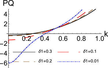
FIGURE 1. The product PQ is plotted versus the carrier wavenumber k, varying δ1, as indicated. Other parameters are δ2=0.9, μ1=0.62, and μ2=0.27.
Figure 2 displays the contour plot and two-dimensional profile of the normalized rogue wave as a function of distance and time. The solution (29) is shown in Figure 2A. Rogue pulses can be intense in a limited, confined region. The rogue pulse is a high peak that concentrates many ions in a tiny area, forming surface nanohillocks. The contour map of the normalized rogue wave as a function of distance and time is shown in Figure 2B. The peak of charged ions correlates with nanohillocks in [14], highlighting the impact of ion-induced modifications on electronic energy deposition by 30-MeV C60 cluster ions in creating energetic plasma. Upon collision, 30-MeV C60 cluster ions deposit high energy and form plasma ions on the surface of the YIG material. Explosions caused by excess energy concentrate charged ions in a concentrated location, creating plasma components outward from the surface. A periodic rogue wave solution (30) is Akhmediev’s breather. Figures 2C,D show the result. Undoubtedly, a periodic pattern can concentrate many ions in periodic confined locations.
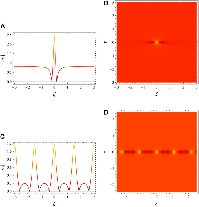
FIGURE 2. (A, B) The Peregrine soliton and (C, D) the Akhmediev breather are depicted for δ1=0.3, δ2=0.5, μ1=0.62, μ2=0.27, p =−0.559, Q =−10.73, τ =0, and ϕ =10.
Figure 3 displays the two-dimensional rogue wave profile reflecting the fluctuation of δ1 (iron concentration). Increasing δ1 decreases the rogue wave profile amplitude. In general, lowering the amplitude causes wave energy to escape from the system and prevents the plasma from concentrating charged ions. In our scenario, increasing δ1 (iron content) wastes energy through a large number of charged ions. This might lower pulse amplitude and shorten nanohillocks.
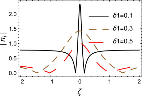
FIGURE 3. The Peregrine soliton is depicted for different values for δ1. The values of the other parameters are δ2=0.9, μ1=0.62, μ2=0.27, p =−0.558, Q =−9.43, τ =0, and ϕ =10.
The Peregrine soliton (PS) is a type of solitary wave that can occur in dispersive nonlinear systems. It is characterized by its sharp peak and rapid decay, and it is known to be highly localized in both space and time. PS was first discovered in the context of water waves, but it has since been shown to exist in a variety of other systems, including plasma [21]. In the context of plasma physics, PS is a solution of the nonlinear Schrödinger equation (NLSE), which describes the propagation of ion-acoustic waves in a plasma. NLSE is a dispersive equation, which means that the phase velocity of a wave depends on its frequency. This dispersion can cause waves to steepen and eventually break, leading to the formation of rogue waves. PS is a type of rogue wave that is particularly well-suited for study in plasma. This is because PS is a localized wave, which means that it can be isolated from other waves in the system. This isolation allows for a more detailed study of the PS’s properties, such as its stability and its interaction with other waves. PS has been experimentally observed in plasma, and it has also been studied extensively in simulations [22, 23]. These studies have shown that PS is a stable wave that can propagate for long distances without breaking. However, PS is also known to be very sensitive to perturbations, which can cause it to break. PS is a fascinating wave that has many potential applications in plasma physics. For example, it could be used to study the propagation of ion-acoustic waves in plasma, or it could be used to develop new methods for controlling plasma waves [24]. PS is also a potential source of rogue waves in plasma, which could have implications for spacecraft operations and other applications. As for the question of whether PS is a true soliton, there is some debate. Solitons are typically defined as waves that can propagate without distortion for long distances. PS is a localized wave that can propagate for long distances, but it is also known to be sensitive to perturbations, which can cause it to break. This suggests that PS may not be a true soliton in the strictest sense of the word [25].
Summary
Our study introduces a hydrodynamic fluid model to explain the production of surface nanohillocks caused by 30-MeV C60 cluster ions hitting YIG. Our study gives a new technique to describe surface nanohillocks using a plasma collective effect of charged particles and rogue waves. We are continuing studying this region and expect to validate the plasma collective impact of the charged particle generation process. Analytically solving hydrodynamic multi-ion fluid equations with background electrons yields a nonlinear Schrödinger equation. Solving the latter gives us feasible regions for localized ion concentration. When rogue waves in this location concentrate charged ions in a very small region, surface nanohillocks occur. As the density ratio δ1 increases, the rogue wave amplitude decreases due to energy distribution among charged ions. Thus, nanohillocks shorten.
Data availability statement
The original contributions presented in the study are included in the article/Supplementary Material; further inquiries can be directed to the corresponding author.
Author contributions
RA: writing–review and editing. LE: methodology and writing–review and editing. MA: writing–review and editing. NA: writing–review and editing. WM: conceptualization and writing–review and editing. IE: investigation, methodology, supervision, and writing–original draft.
Funding
The author(s) declare financial support was received for the research, authorship, and/or publication of this article. The study was supported by Princess Nourah Bint Abdulrahman University Researchers supporting project number (PNURSP2024R399), Princess Nourah bint Abdulrahman University, Riyadh, Saudi Arabia.
Conflict of interest
The authors declare that the research was conducted in the absence of any commercial or financial relationships that could be construed as a potential conflict of interest.
Publisher’s note
All claims expressed in this article are solely those of the authors and do not necessarily represent those of their affiliated organizations, or those of the publisher, the editors and the reviewers. Any product that may be evaluated in this article, or claim that may be made by its manufacturer, is not guaranteed or endorsed by the publisher.
References
1. Ritter R, Wilhelm R, Ginzel R, Kowarik G, Heller R, El-Said A, et al. Pit formation on poly (methyl methacrylate) due to ablation induced by individual slow highly charged ion impact. EPL (Europhysics Letters) (2012) 97:13001. doi:10.1209/0295-5075/97/13001
2. Moslem WM, El-Said AS, Sabry R, Bahlouli H. Nanostructuring of sapphire by ion-induced plasma. Results Phys (2023) 46:106297. doi:10.1016/j.rinp.2023.106297
3. Ochedowski O, Lehtinen O, Kaiser U, Turchanin A, Ban-d’Etat B, Lebius H, et al. Nanostructuring graphene by dense electronic excitation. Nanotechnology (2015) 26:465302. doi:10.1088/0957-4484/26/46/465302
4. Jensen J, Dunlop A, Della-Negra S, Toulemonde M. A comparison between tracks created by high energy mono-atomic and cluster ions in y3fe5o12. Nucl Instr Methods Phys Res Section B: Beam Interactions Mater Atoms (1998) 146:412–9. doi:10.1016/s0168-583x(98)00442-x
5. Singhal R, Singh F, Tripathi A, Avasthi D. A comparative study of ion-induced damages in c60 and c70 fullerenes. Radiat Effects Defects Sol (2009) 164:38–48. doi:10.1080/10420150802479638
6. Moslem WM, El-Said AS, Morsi SA, Sabry R, Yahia ME, El-Labany SK, et al. On the formation of nanostructures by inducing confined plasma expansion. Results Phys (2019) 15:102696. doi:10.1016/j.rinp.2019.102696
7. Yahia ME, Tolba RE, El-Bedwehy NA, El-Labany SK, Moslem WM. Rogue waves lead to the instability in gan semiconductors. Scientific Rep (2015) 5:12245. doi:10.1038/srep12245
8. Yahia ME, Tolba RE, Moslem WM. Super rogue wave catalysis in titan’s ionosphere. Adv Space Res (2021) 67:1412–24. doi:10.1016/j.asr.2020.11.027
9. Mouhammadoul BB, Alim AAA, Tiofack C, Mohamadou A, Alrowaily AW, Ismaeel S, et al. On the super positron-acoustic rogue waves in q-nonextensive magnetoplasmas. Phys Fluids (2023) 35:9. doi:10.1063/5.0144915
10. Farokhi B, Shahmansouri M, Kourakis I. Modulated transverse off-plane dust-lattice wave packets in hexagonal two-dimensional dusty plasma crystals. Phys Plasmas (2009) 16:11. doi:10.1063/1.3121221
11. Shahmansouri M, Alinejad H, Tribeche M. Breather structures in degenerate relativistic non-extensive plasma. J Plasma Phys (2017) 83:905830303. doi:10.1017/s0022377817000332
12. Alinejad H, Shahmansouri M. Evolution of dissipative low-frequency rogue waves in superthermal dusty plasmas. IEEE Trans Plasma Sci (2019) 47:4378–84. doi:10.1109/tps.2019.2932504
13. El-Said A. Tracks of 30-mev c60 clusters in yttrium iron garnet studied by scanning force microscopy. Nucl Instr Methods Phys Res Section B: Beam Interactions Mater Atoms (2009) 267:953–6. doi:10.1016/j.nimb.2009.02.020
14. Moslem WM, El-Said AS, Sabry R, Shalouf A, El-Labany SK, Bahlouli H. Nonlinear phenomenon in nanostructures creation by fast cluster ions. Phys Lett A (2017) 381:102–5. doi:10.1016/j.physleta.2016.10.008
15. Morsi SA, Moslem WM, El-Said AS, Bahlouli H. Creation of surface nanometer-scale plasma region by irradiation with slow highly charged ions. Physica Scripta (2020) 95:095602. doi:10.1088/1402-4896/aba865
17. Kourakis I, Shukla PK. Exact theory for localized envelope modulated electrostatic wavepackets in space and dusty plasmas. Nonlinear Process Geophys (2005) 12:407–23. doi:10.5194/npg-12-407-2005
18. Peregrine DH. Water waves, nonlinear Schrödinger equations and their solutions. ANZIAM J (1983) 25:16–43. doi:10.1017/s0334270000003891
19. Akhmediev N, Korneev V. Modulation instability and periodic solutions of the nonlinear Schrödinger equation. Theor Math Phys (1986) 69:1089–93. doi:10.1007/BF01037866
20. Alharthi NS, Tolba RE, Moslem WM. Nonlinear propagation of dust-acoustic waves and its modulation instability. Physica Scripta (2023) 98:115236. doi:10.1088/1402-4896/ad007e
21. Bailung H, Sharma S, Nakamura Y. Observation of peregrine solitons in a multicomponent plasma with negative ions. Phys Rev Lett (2011) 107:255005. doi:10.1103/physrevlett.107.255005
22. Sharma S, Bailung H. Observation of hole peregrine soliton in a multicomponent plasma with critical density of negative ions. J Geophys Res Space Phys (2013) 118:919–24. doi:10.1002/jgra.50111
23. Pathak P, Sharma SK, Nakamura Y, Bailung H. Observation of ion acoustic multi-peregrine solitons in multicomponent plasma with negative ions. Phys Lett A (2017) 381:4011–8. doi:10.1016/j.physleta.2017.10.046
24. Moslem WM, Shukla PK, Eliasson B. Surface plasma rogue waves. Europhysics Lett (2011) 96:25002. doi:10.1209/0295-5075/96/25002
Keywords: rogue waves, nanohillocks, ion-induced localized plasma, modulational instability, nonlinear Schrödinger equation
Citation: Altuijri R, El Maati LA, Ahmad M, Alharthi NS, Moslem WM and Elkamash IS (2023) Evolution of nanohillocks by fullerene ion-induced localized plasma. Front. Phys. 11:1254477. doi: 10.3389/fphy.2023.1254477
Received: 07 July 2023; Accepted: 29 November 2023;
Published: 22 December 2023.
Edited by:
Kazuya Hayata, Sapporo Gakuin University, JapanCopyright © 2023 Altuijri, El Maati, Ahmad, Alharthi, Moslem and Elkamash. This is an open-access article distributed under the terms of the Creative Commons Attribution License (CC BY). The use, distribution or reproduction in other forums is permitted, provided the original author(s) and the copyright owner(s) are credited and that the original publication in this journal is cited, in accordance with accepted academic practice. No use, distribution or reproduction is permitted which does not comply with these terms.
*Correspondence: I. S. Elkamash, ZWxrYW1hc2hpQGdtYWlsLmNvbQ==