 Ximei Qin
95% of researchers rate our articles as excellent or good
Learn more about the work of our research integrity team to safeguard the quality of each article we publish.
Find out more
ORIGINAL RESEARCH article
Front. Phys. , 13 July 2023
Sec. Statistical and Computational Physics
Volume 11 - 2023 | https://doi.org/10.3389/fphy.2023.1230299
A hybrid axisymmetric conservative phase-field lattice Boltzmann method is applied to investigate the influence of Marangoni number (Ma), density ratio (ρr), and radius ratio (Rr) on thermocapillary migration of a deformable hollow droplet with difference in variable fluid properties, where ρr (Rr) is the density (radius) ratio of the hollow part of the droplet. The isotherms show that heat transfer around the hollow droplet is changed from conduction to convection with the increase in Ma. However, the temperature gradient across the hollow droplet decreases with Ma, which induces a small magnitude of migration velocity. When ρr is increased, the isotherms are accumulated around the hollow droplet front with a large temperature gradient, which enhances the hollow droplet migration, while the migration velocity is decreased with the increase in Rr. It is observed that thermocapillary migration of the hollow droplet finally becomes a pure droplet with the influence of aforementioned parameters, and it experiences interface breaking and coalescing, which causes a large transient variation in migration velocity. The magnitude of this transient variation in migration velocity is not obviously affected by Ma but significantly affected by ρr and Rr. The measured evolution of d (the dimensionless distance between inner and outer fronts of the hollow droplet) demonstrates that ρr has a significant influence on the reduction rate of d in comparison with the influence of Ma and Rr. Similar influences on the relative migration velocity between the fluid of the hollow part inside the droplet and the sealed fluid of the droplet are observed.
When a droplet/bubble is immersed into another immiscible fluid, it moves due to an imposed temperature gradient. Due to a decreasing function of surface tension on temperature for most fluids, the droplet/bubble moves from a low temperature region to a high temperature region under negligible buoyancy effect. This phenomenon is well known as thermocapillary convection or Marangoni convection. It provides a feasible way to manipulate and control the droplet/bubble in the microgravity environment or microfluidic devices, and it also plays an important role in practical applications such as microfluidic system, crystal growth, space welding, and food processing. Numerous investigations using theoretical analysis, experiment, and numerical simulation are performed to understand the mechanism of thermocapillary migration of a droplet/bubble in the microgravity environment [1] or microfluidic devices [2].
The first experimental study on thermocapillary migration of a single spherical droplet was attributed to Young et al. [3] who also presented a theoretical prediction of terminal migration velocity for a spherical droplet at the limit of zero Reynolds (Re) and Marangoni (Ma) numbers. Later, the asymptotic analysis method was used to study droplet/bubble migration at finite Re and Ma numbers [4, 5]. However, the droplet/bubble was assumed to be non-deformable during its migration by most of the theoretical analyses, which was only valid at large surface tension without fluid convection. In Ref. [6], thermocapillary behavior of multiple deformable droplets was investigated by the front-tracking/finite-difference method [7] in two and three dimensions; it was observed that the droplets formed layers with the effect of mono-dispersed and poly-dispersed cases at moderate Re and Ma numbers. Yin et al. [8] developed an efficient numerical scheme to investigate different migration processes of isolated spherical drops with various Ma numbers, and the results showed a more complicated process, longer time, and larger distance for the droplet to reach the steady state at a large Ma number. Yin and Li [9] systematically investigated the interaction of two non-merging droplets by the front-tracking method to show the importance of heat wake behind the leading droplet for droplet interaction and showed different final droplet distances and transient migration processes for various non-dimensional parameters. The finite-volume/level-set approach was also developed to study the thermocapillary migration and interactions among immiscible deformable droplets with a variable fluid property ratio [10]. In Ref. [11], a parallel three-dimensional volume of fluid method was developed for studying thermocapillary migration of a deformable droplet. In Refs [12, 13], the phase-field theory-based method was applied to simulate two-dimensional (2D) and three-dimensional (3D) thermocapillary migration of a deformable droplet. Moreover, the lattice Boltzmann method (LBM) was extended to investigate thermocapillary migration of deformable droplet and droplet interactions [14–16].
Thus, thermocapillary migration of a droplet/bubble has been studied in various ways, and many of the underlying physical mechanisms have been well understood. Nevertheless, the majority of these works considered the pure bubble or droplet immersed into an ambient fluid, and the effect of the hollow part inside the droplet on its thermocapillary migration was not covered. In fact, the hollow droplets are frequently observed in nature and engineering applications such as the hollow rain droplet formed by water and air, thermal liquid spraying, and diesel injection nozzles. Several investigations were performed, and the dynamics and heat transfer of the hollow droplet with those of the pure droplet were compared [17–22]. Gulyaev et al. [17] experimentally studied a spherical hollow droplet impinging onto a solid surface and observed the phenomena of counter-jet features in a wide range of Reynolds and Weber numbers. Kumar and co-workers conducted a series of investigations on the impact behavior of a hollow droplet onto a substrate [18–20]. They found that the impacting and spreading of a hollow droplet on a flat surface was quite different from the behavior of a conventional pure droplet and observed that the droplet’s void fraction and its distribution had significant influences on the impact dynamics and final splat shape. Recently, Li et al. [21, 22] simulated the dynamics and heat transfer of a hollow droplet impact on a dry flat surface and observed the counter-jet features and complex transient heat transfer between the hollow droplet and solid surface in comparison with an analogous pure droplet. Nasiri et al. [23] investigated the hollow droplet impact on a solid surface through different surface wettabilities, liquid properties, and impact velocities, and the results showed that the mechanism of the post-impact process was different in comparison with pure droplet impact. Naidu et al. [24] studied the effect of air volume, height of impact, and liquid viscosity of a hollow droplet on the maximum spread and the volume of counter-jet.
The aforementioned findings showed a significant difference between the hollow droplet and pure droplet in the dynamics spreading and heat transfer. However, the author is not aware of studies devoted to exploring the transport mechanism of hollow droplet migration. Therefore, the aim of this paper is to investigate the effect of hollow fluid inside the droplet on the transient migration of the droplet together with different Ma, density ratios (ρr), and radius ratios (Rr), and a hybrid axisymmetric conservative phase-field LBM (ACPFLBM) is applied to study the thermocapillary migration of the hollow droplet with difference in variable fluid properties. The hydrodynamic Navier–Stokes equation and the interface capturing equation are solved by ACPFLBM, whereas the convection–diffusion equation for the temperature field is solved by the second-order isotropic finite difference method and the Runge–Kutta method. This hybrid ACPFLBM model is first validated by a stationary droplet at a uniform temperature field and thermocapillary migration of a deformable droplet at the limit of zero Re and Ma numbers. Subsequently, numerical simulations are carried out to investigate the influence of Ma, ρr, and Rr on the thermocapillary migration of the hollow droplet.
In the thermal multiphase flow system, the fluid surface tension usually varies due to the non-uniform temperature distribution, and the effect of tangential gradient of surface tension or Marangoni stress should be considered in the interface force F, which can be written as [25]
where ∇s = (I − nn) ⋅∇ is the tangential gradient operator along the interface, σ is the fluid surface tension, δ is the regularized delta function, and κd = ∇ ⋅n is the curvature of the phase interface, with n = ∇c/|∇c| as the outward pointing unit normal vector and c as an order parameter. With the concept of CSF, δ is set at δ = 3D|∇c|2/2, and the interface force F in Eq. 1 can be explicitly written as [14]
where D is the interface thickness and μ is the chemical potential which is defined by the variational derivative of mixing free energy E, namely, μ = δE/δc = μ0 − κ∇2c, where μ0 = ∂E/∂c is the bulk chemical potential and κ is the gradient coefficient. In phase-field theory, the order parameter c is widely applied to identify the phase regions, e.g., when the region is occupied by one fluid, c is equal to one (c = 1), whereas when the region is also occupied by another fluid, c is given by c = 0. The mixture free energy E of the two-phase flow can be defined as [26]
where E0 is the bulk free energy, and it can be approximated by E0(c) = βc2 (c − 1)2 in the phase-field theory. The relationship between β, κ, D, and σ can be expressed as
For most fluids, surface tension is a decreasing function with temperature, and the relationship between surface tension and temperature can be assumed as a linear relationship, which can be given as
where σ0 is the reference surface tension at temperature T0 and σT = ∂σ/∂T is the rate of surface tension change with temperature T. Then, the interface force F can be further simplified as
When the interface dynamic flow is driven by temperature difference, the evolution of fluid–fluid interface can be captured using the conservative Allen–Cahn equation, and the interface force in Eq. 6 should be incorporated into the NSE as follows:
where M is the mobility, s = 4c (c − 1)n/D, ρ is the fluid density, p is the dynamic pressure, η is the dynamic viscosity, and cp and λ are the specific heat and thermal conductivity of the fluid, respectively.
When thermocapillary flow has an axisymmetric property without swirl, the following axisymmetric governing equations can be directly derived by the coordinate transformation from Eqs 7–10
where
where
The previous section showed that the evolution of fluid–fluid interface can be captured by the axisymmetric conservative Allen–Cahn equation (ACACE) shown in Eq. 11 for thermocapillary flow in the axisymmetric system. In this work, LBM is applied to solve the interface capturing equation, and its evolution equation for the order parameter c can be written as [27–29]
where hi is the distribution function, τh is a single relaxation time, ξi is the molecular velocity in the axisymmetric system, and
with
where Γ is an adjustable parameter, u = (ux, ur) is the fluid velocity in the x − r plane, cs is the sound speed, and ωi is the weight coefficient of the corresponding discrete velocity model. The source term Si in Eq. 16 is defined as follows:
Through the standard discretization procedure in LBM, the discretized form of Eq. 16 can be derived by
where ωh = 2δt/(2τh + δt). Using Eqs 17–20, the order parameter c can be calculated by hi, which can be defined as
and the relationship between mobility M and τh is
The hydrodynamic equations of Eqs 12, 13 can be solved by another incompressible axisymmetric LBM, and the discrete axisymmetric Boltzmann equation with the Bhatnagar–Gross–Krook collision operator without swirl can be written as [27–29]
where fi is the density distribution function and τ is the single relaxation time, and the equilibrium density distribution function
where Γi(u) is defined as
Fi is the force term, and its explicit form can be written as
with
Similar to the simple transformation technique used in single/two-phase flow to reduce the compressibility effect [26], a new distribution function gi is defined as [30]
Accordingly, the new evolution equation for gi is derived from Eq. 22as follows:
where the modified equilibrium distribution function
By applying the trapezoidal discretization rule to Eq. 27, the simplified evolution equation of LBM for hydrodynamics can be derived assuming a low Mach number, where ∇p (Γi(u) − Γk (0)) ∼ O (|u|3) has been used with δp ∼|u|2:
where ωf = 2δt/(2τ + δt), and the distribution function
The dynamic pressure and velocity of the fluid can be calculated by moments of
and the relationship between η and τ can be given by
In the axisymmetric thermocapillary flow, the flow motion is driven by the temperature difference. In this work, it is assumed that the pressure work and viscous dissipation term in the energy equation can be ignored, and the heat transfer in the two-phase fluid system can be governed using Eq. 14, which can be rewritten as
To solve this equation, the second-order explicit Runge–Kutta (RK) method is applied to discretize the time derivative in Eq. 32 from t to t + δt, and the time matching can be updated by following two substeps [14, 31]:
while the spatial derivative terms in
Thermocapillary-driven flow is usually characterized by some dimensionless parameters such as Re, Ma, capillary number (Ca), ρr, viscosity ratio (ηr), conductivity ratio (λr), and specific heat ratio (cpr) which can be defined as follows:
where the subscripts of 1 and 2 denote the disperse and continuous phases and the parameters of U and L are the characteristic velocity and length of the fluid system, respectively. Some benchmark problems are demonstrated to validate the present hybrid ACACE LBM by including a stationary droplet immersed into a uniform temperature system, and thermocapillary migration of the deformable droplet/bubble at negligible Ma and Re numbers and thermocapillary migration of the hollow droplet are systematically investigated. Due to the axisymmetric property of these problems, such flows can be viewed as quasi-two-dimensional problems in the meridian plane. In this work, a two-dimensional nine-discrete-velocity model is applied to the present hybrid ACACE LBM with the corresponding weight coefficient ωi chosen as ω0 = 4/9, ω1−4 = 1/9, and ω5−8 = 1/36.
The first test problem is a stationary droplet immersed into another fluid with a uniform temperature distribution, which is used to validate the present hybrid ACACE LBM. Initially, the center of the stationary droplet is located at xc = (Lx/2, 0) with radius R = Lx/10, and the uniform temperature field T0 = 1 is imposed in the Lx × Lr fluid domain. For this case, the uniform temperature field gives a stationary droplet, and Ma = Re = Ca = 0. The symmetric boundary condition is applied to the symmetry axis, and the non-slip boundary condition is implemented for other boundaries. In the simulation, the computational domain is divided into Lx × Lr = 200 × 100 mesh, the fluid properties are chosen as ρr = 0.1, ηr = 0.1, λr = 10, and cpr = 1, and the other model parameters are given as τh = 0.5, D = 4, and M = 0.01, with the surface tension σ0 = 0.001. The initial profile of c is given as
Due to the uniform temperature distribution in this case, there is no contribution of Marangoni stress to drive the droplet, and thus it should be stationary. When the system reaches its equilibrium state, the distribution of c across the droplet’s center is compared with its initial profile, as shown in Figure 1A. It is shown that the prediction of the order parameter c by the present hybrid ACACE LBM agrees well with the initial profile, which implies that the droplet indeed keeps stationary during the simulation. The temperature profile across the center of the droplet in the x direction is also plotted in Figure 1B, and the result shows that the temperature is a constant value in this two-phase system, which induces a zero Marangoni stress along the phase interface.
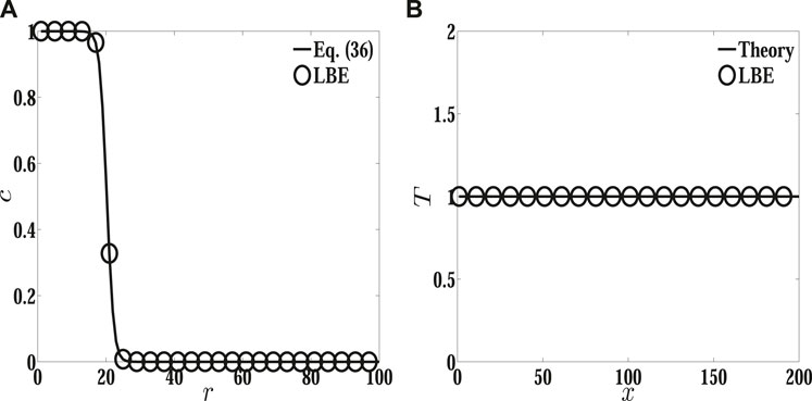
FIGURE 1. Steady profiles of order parameters and temperature across the droplet. (A) Profile of c across the center of the droplet in the r direction and (B) temperature distribution T across the center of the droplet in the x direction.
Thermocapillary migration of a spherical droplet/bubble in an infinite domain with a constant temperature gradient |∇T∞| at the limit of 0 Ma and small Re numbers is widely used to validate the numerical method. In this problem, a theoretical prediction for the terminal migration velocity UYGB of a spherical droplet/bubble with radius R can be given as [3]
where U is the characteristic velocity defined as
Initially, the center of the spherical droplet is located at xc = (Lx/2, 0) in a fluid domain Lx × Lr = 16R × 4R, and a linear temperature distribution is imposed in the x direction with constant temperatures Tc and Th (Th > Tc) at the bottom and top walls, respectively. Similar to the previous case, the symmetry boundary condition is applied to the symmetry axis and the non-slip boundary condition is used for other boundaries. In the simulation, the droplet radius is R = 40, the physical properties of the fluids are set at ρr = 1, viscosity ratio ηr = 1, thermal conductivity ratio λr = 1, and specific heat ratio cpr = 1, with Tc = 0 and Th = 64, and the dimensionless parameters are given as Re = Ma = Ca = 0.1. Figure 2 shows the velocity pattern and temperature field around the droplet. It is shown that fluid currents are observed around the droplet. The surrounding fluid is moving from a high temperature region to a low temperature region, while the droplet is rising from the cold region to the hot region, which is the result of a decreasing function of surface tension force on temperature along the interface. The isotherms across the droplet are almost straight lines, which implies that the heat transfer around the droplet is through the conduction process. The aforementioned phenomena have been reported by many researchers [8,10,15]. In Figure 3, the dimensionless migration velocity u* versus the dimensionless time t* predicted by the present hybrid LBM is compared with the YGB theory [3], where u* is defined as u* = u/uYGB, with u as the droplet migration velocity computed by u = ∫V,c≥0.5rcuydV/∫V,c≥0.5rcdV, and t* is defined as t* = tU/R. The prediction of u by the present LBM is 4.280 × 10⁻⁵, while the YGB theory gives 4.216 × 10⁻⁵, and the relative error is 1.5%, which gives a good quantitative agreement with the YGB theory [3].
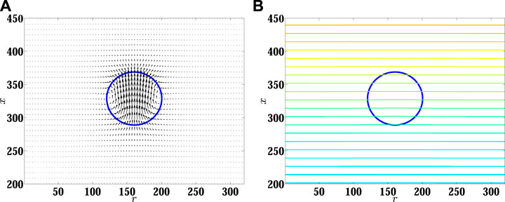
FIGURE 2. Velocity patterns and temperature fields around the rising droplet.
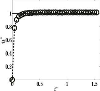
FIGURE 3. Normalized migration velocity of the spherical droplet versus time at Ma = Re = 0.1. The line represents the analytical prediction by the YGB theory, and the dashed line with open circles represents the present results.
Once the capability of the present hybrid ACACE LBM is demonstrated by the previous benchmark tests, then it is applied to investigate the thermocapillary migration of a deformable hollow droplet under a constant temperature gradient along the x direction. As shown in Figure 4, a concentric hollow droplet is composed of inner (fluid 2) and outer (fluid 1) parts with an inner radius R2 and outer radius R1 immersed into the surrounding fluid 2. Initially, all fluids are stationary, and a linear temperature profile is imposed along the x direction with a low temperature Tc and a high temperature Th at the bottom and top walls respectively, and the center of the hollow droplet is located at (Lx/2, 0) in a physical domain Lx × Lr = 16R2 × 4R2. In the simulation, the parameters Re = 1.0, Ca = 0.1, cp1 = cp2 = 1.0, Tc = 0, Th = 64, T0 = 32, σT = −10–5, and R2 = 40 are kept fixed with ηr = λr = ρ1/ρ2, and the same boundary conditions are used as shown in Section 4.1; then, the effect of Ma, density ratio ρr, and radius ratio Rr = R2/R1 between the inner and outer radius of the hollow droplet on the performance of hollow droplet thermocapillary migration is studied.
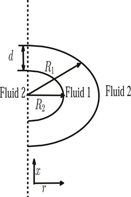
FIGURE 4. Configuration of hollow droplet migration.
First, the influence of Ma varied from 1 to 1,000 on the hollow droplet migration, and the interaction between fluid 2 of the hollow part inside the droplet and sealed fluid 1 is investigated. In the simulation, Rr and ρr are set to 1/2 and 1, respectively. In Figure 5, the migration velocity (normalized to ur = U) of pure and hollow droplets versus the dimensionless time t* is plotted at Ma = 100. When the hollow droplet migrates, the interaction between fluid 2 of the hollow part inside the droplet, sealed fluid 1 of the droplet, and surrounding fluid 2 will appear, and some differences are observed in the migration velocity of the pure and hollow droplets. More specifically, it is shown in Figure 5 that the magnitude of migration velocity of the hollow droplet is smaller than that of the pure droplet at the early time before fluid 2 of the hollow part inside the droplet coalesces with surrounding fluid 2. When fluid 2 of the hollow part inside the droplet crosses through the interface formed by fluid 1 and surrounding fluid 2, the migration velocity of the hollow droplet is suddenly accelerated and then gradually slowed down to a lower value than that by pure droplet migration. Figure 6 shows the comparison of time sequences of the temperature field between the migration of pure and hollow droplets at Ma = 100. For the pure droplet migration, the isotherms are gradually accumulated around the front of the droplet with a relatively large temperature gradient along the migration direction, and a thermal wake is formed behind the droplet with a relatively small temperature gradient along the migration direction, which are consistent with the results in many previous works [8,10,15]. For the hollow droplet migration, fluid 2 of the hollow part inside the droplet migrates faster than the sealed fluid 1 in the hollow droplet, and the isotherms between the inner and the outer droplet fronts are a bit denser than those in the pure droplet. Since the accumulated isotherms are around the front of the hollow droplet, a higher temperature gradient can lead to a larger driving force, and it is observed that the transient migration velocity of the hollow droplet is larger than that of the pure droplet when the interface interaction in the hollow droplet enhances the temperature gradient, as shown in Figures 5, 6.The effect of the Ma number on the time evolution of hollow droplet migration velocity and the transient temperature distribution around the hollow droplet is shown in Figures 7, 8. The time evolution of hollow droplet migration velocity shows that all the transient migration velocities have a sudden enhancement and gradually reduce to a value for different Ma numbers when fluid 2 of the hollow part inside the droplet crosses the interface and coalesces with surrounding fluid 2. The magnitude of migration velocity is gradually reduced with the increase in Ma. The overshoot of migration velocity occurs at the early state and shows a significant difference with the increase in the Ma number. The hollow droplet becomes a pure droplet in the later state, and the migration velocity decreases with the increase in the Ma number in all simulations, which has been observed by the previous works for pure droplet migration [8, 10, 15]. From Figure 8, it is observed that the temperature field around the droplet is different at different Ma as the time t* increased. The isotherms show that the heat transfer through the hollow droplet is almost a conduction process at the early time. As time increased, the isotherms demonstrate that the heat transfer is changed from conduction to convection around the hollow droplet before fluid 2 of the hollow part inside the droplet merged with surrounding fluid 2. Later, it forms a pure droplet. The isotherms undergo less deformation at low Ma, as shown in Figure 8A, and much more deformation at large Ma, as shown in Figures 6B, 8B, after the formation of the pure droplet at t* = 40 and 80, which are similar to those in a pure droplet migration simulation [8, 10, 15]. As shown in Figure 8, it shows that the isotherms and the shape of the hollow inside the droplet are not changed remarkably before it coalesces, while the isotherms and interface curvature of fluid 1 in the hollow droplet change significantly during the coalescence process, which induces a large migration velocity and causes a large isotherm deformation. Moreover, the measured time evolution of the distance d (as shown in Figure 4) between the inner and outer droplet fronts is presented in Figure 9 which is normalized by Ro for different Ma numbers. It is shown that d is reduced to zero faster at small Ma numbers than that at large Ma numbers, where fluid 2 of the hollow part inside the droplet coalesces with surrounding fluid 2. Similar to the effect on velocity migration of the hollow droplet, the temperature gradient across the hollow part inside the droplet is large at small Ma numbers, while it becomes relatively small at large Ma numbers.
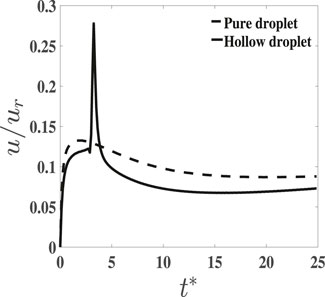
FIGURE 5. Migration velocity of the pure droplet and hollow droplet versus time t* with Ma =100.
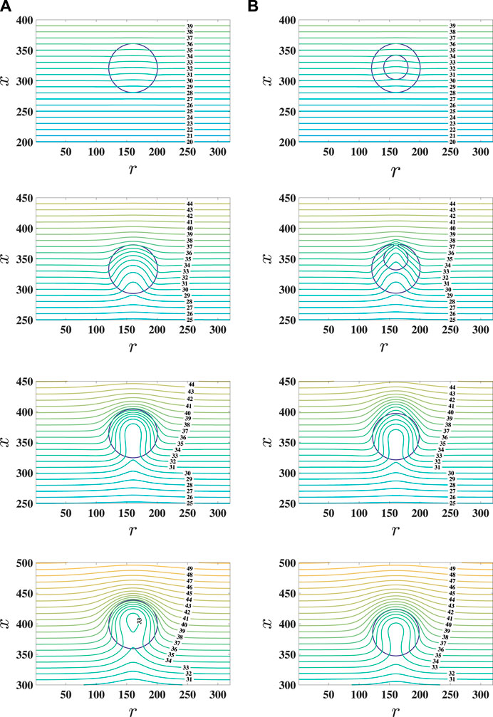
FIGURE 6. Snapshots of the temperature field around the pure droplet and hollow droplet with Ma =100 at t*=1, 11, 40, and 80 (from top to bottom rows). The columns of (A) pure droplet and (B) hollow droplet.
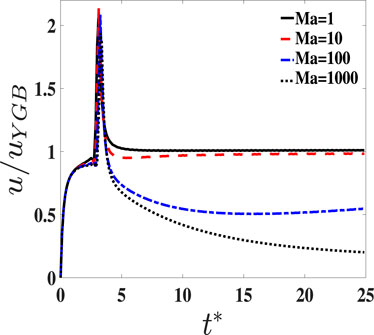
FIGURE 7. Migration velocity of the hollow droplet versus time t* with Ma =1,10,100, and 1,000.
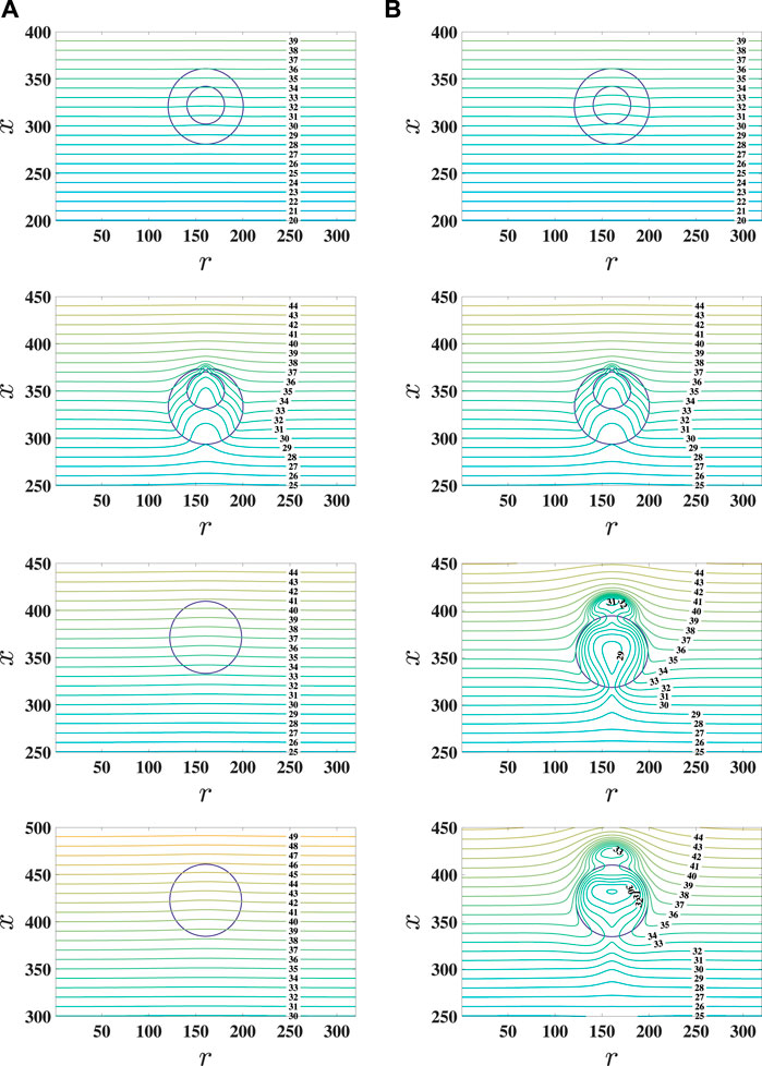
FIGURE 8. Snapshots of the temperature field around the hollow droplet at t*=1, 11, 40, and 80 (from top to bottom rows). The columns of (A) Ma = 1 and (B) Ma = 1,000.
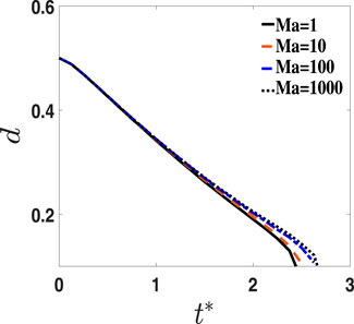
FIGURE 9. Time evolution of d with Ma =1,10,100, and 1,000.
In this section, the influence of the density ratio ρr on the transient evolution of the hollow droplet with Rr = 1/2 and Ma = 1.0 is performed. In the simulation, ρr varies from 1 to 100, and the other parameters are the same as those in the previous subsection. In Figure 10, the transient hollow droplet migration is measured at different ρr values. The time evolution of migration velocity shows that the magnitude of migration velocity is increased with ρr, and the snapshots of the temperature field are presented in Figure 11. When the density ratio is small at ρr = 1, as shown in Figure 8, the isotherms show that the heat transfer takes place through conduction through the hollow droplet before coalescence, while the isotherms are accumulated around the front and back of the hollow droplet with a large density ratio. These phenomena demonstrate that the larger density ratio used the larger temperature gradient that occurs across the hollow droplet, which induces a large driven force for the hollow droplet migration. When fluid 2 of the hollow part inside the droplet merges with the surrounding fluid 2, it also induces a large oscillation on the migration velocity, a large shape change, and isotherm accumulation for the droplet as shown in Figure 11, and it can be observed that the induced amplitude variation in migration velocity is increased with the increase in ρr. Afterward, the hollow droplet becomes a pure droplet, and the isotherms gather around the droplet at a large density ratio, which induces large velocity migration. Similar results of the influence of the density ratio on the pure droplet migration were observed, and its migration velocity was enhanced with the large density ratio [14].
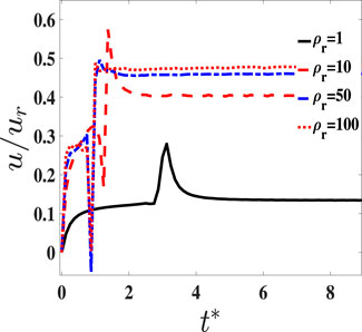
FIGURE 10. Migration velocity of the hollow droplet versus time t* with ρ =1,10,50, and 100.
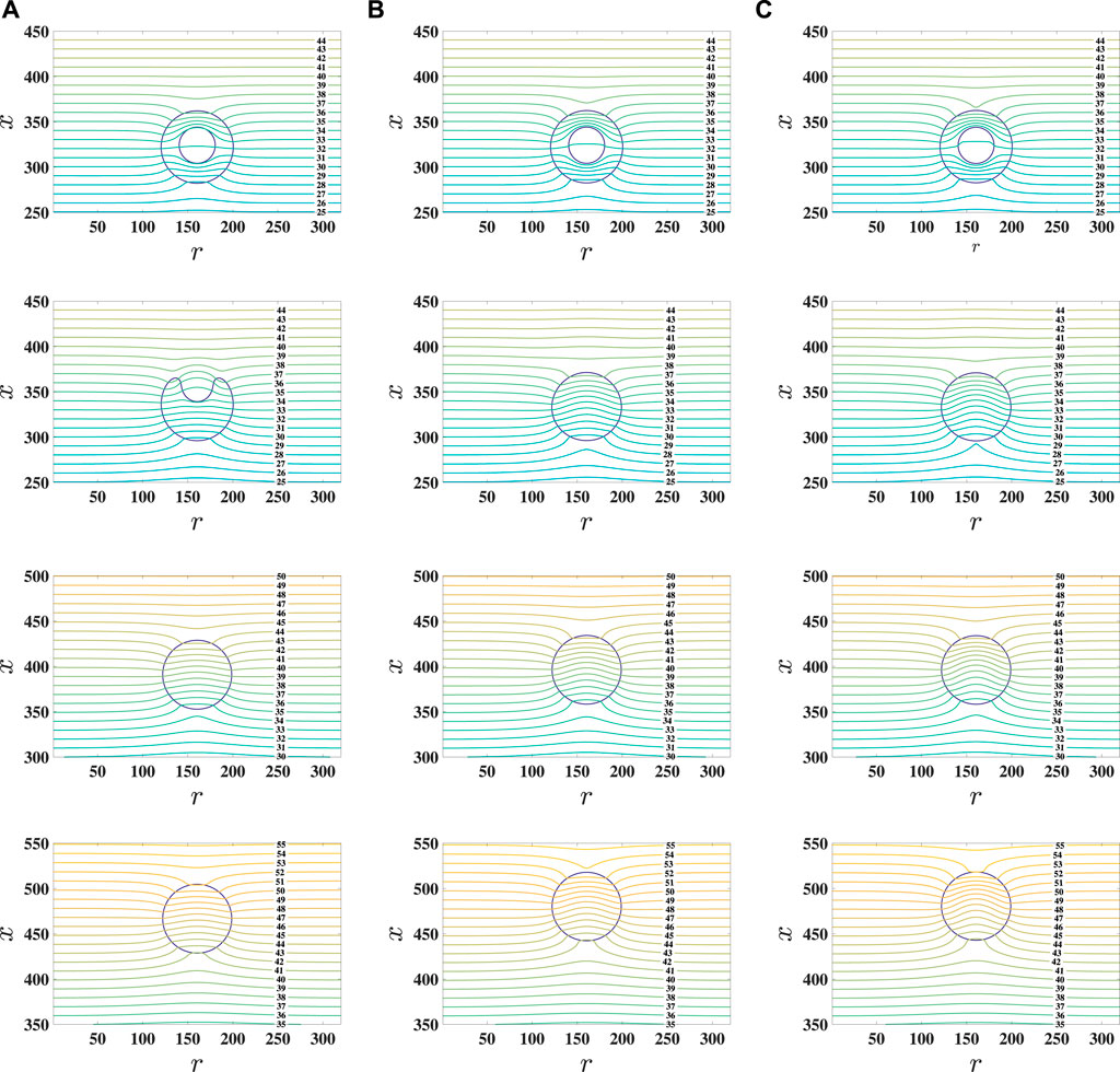
FIGURE 11. Snapshots of temperature field around the hollow droplet at t*=1, 5, 20, and 40 (from top to bottom rows). The columns of (A) ρ = 10, (B) ρ = 50, and (C) ρ = 100.
In Figure 12A, the distance d is measured for different ρr values. It is shown that d decreases fast with a large density ratio, which implies that fluid 2 of the hollow part inside the droplet merges faster at large ρr values than at small values. The reason is that the large density ratio gives a large λr which can make the isotherms accumulate around the hollow droplet as shown in Figure 11 and induces a large migration velocity for fluid 2 of the hollow part inside the droplet. For the comparison with large Ma numbers, the time evolution of d is presented at Ma = 100 as shown in Figure 12B. It is shown that the change rate of d is slowed down at Ma = 100. It is consistent with the results of the influence of Ma on d in the previous subsection, and this further implies that the density ratio does not change this trend on d by the influence of Ma.
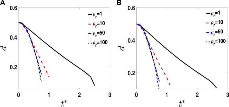
FIGURE 12. Time evolution of d with ρr =1, 10, 50, and 100. (A) Ma = 1 and (B) Ma = 100.
The comparison of pure and hollow droplets in Section 4.2.1 shows that fluid 2 of the hollow part inside the droplet has obvious effect on the transient thermocapillary migration, and the previous study showed that the influence of droplet void fractions on the impact behavior of a hollow droplet and its final splat shape onto a substrate is significantly different from that of the pure droplet [19]. In this subsection, the influence of Rr on thermocapillary migration is first studied with Ma = 1, ρr = 1, and Rr varying from 0 to 3/4, where Rr is tuned by R2. The transient migration velocity is plotted in Figure 13A, and the results show that the amplitude variation in migration velocity is increased with Rr. The interaction between fluid 2 of the hollow part inside the droplet and sealed fluid 1 of the droplet is enhanced with the increase in Rr, and a large value of Rr causes a large curvature effect which induces a large amplitude variation in migration velocity for the hollow droplet. When the Ma number is increased to 100, as shown in Figure 13B, the migration velocity is reduced compared to Ma = 1 at different values of Rr. As discussed previously on the influence of Ma numbers at Rr = 1/2 as shown in Figure 8, the temperature gradient across the hollow droplet is decreased with the increase in Ma, which causes a small migration velocity with a large Ma number.
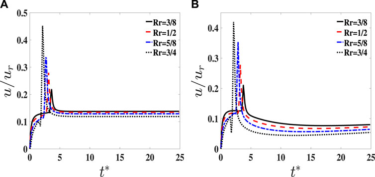
FIGURE 13. Migration velocity of the hollow droplet versus time t* with Rr = 3/8,1/2,5/8, and 3/4. (A) Ma = 1 and (B) Ma = 100.
In Figure 14, the time evolution of d is measured for three cases with Rr = 3/8, 1/2, 5/8, and 3/4: (A) ρ = 1, Ma = 1; (B) ρ = 1, Ma = 100; and (C) ρ = 50, Ma = 1. The results show that d reaches zero at a short time with large Rr for each case, due to the small initial value of d, and fluid 2 of the hollow part inside the droplet with large Rr merges faster with surrounding fluid 2 than that with the small Rr. When Ma increases to 100, the time evolution of d is slowly reduced to zero in comparison with Ma = 1 at different values of Rr; however, the differences are not significant. While the density ratio is increased to ρr = 50, fluid 2 of the hollow part inside the droplet merges faster than that with ρr = 1. As shown in Figure 15A, Ma has no significant influence on the relative migration velocity between fluid 2 of the hollow part inside the droplet (u2) and sealed fluid 1 of the droplet (u1) denoted by u12 = u2 − u1, which is measured before fluid 2 of the hollow part inside the droplet that coalesces with surrounding fluid 2, whereas ρr and Rr have obvious influence on u12 as shown in Figures15B, C. Compared with the effect of Rr, the change in density ratios can significantly affect the relative migration velocity u12 in Figure 15B, the reason why the density ratio ρr has a significant influence on the time evolution of d in contrast to Rr and Ma.
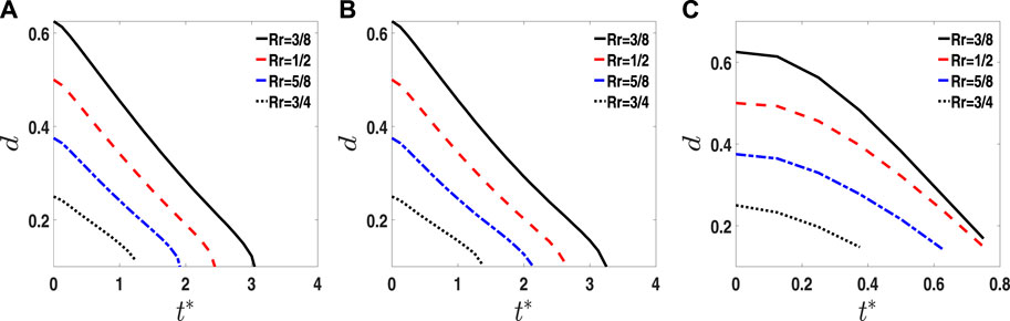
FIGURE 14. Time evolution of d with Rr =3/8,1/2,5/8, and 3/4. (A) ρ =1, Ma =1; (B) ρ =1, Ma =100; and (C) ρ =50, Ma =1.
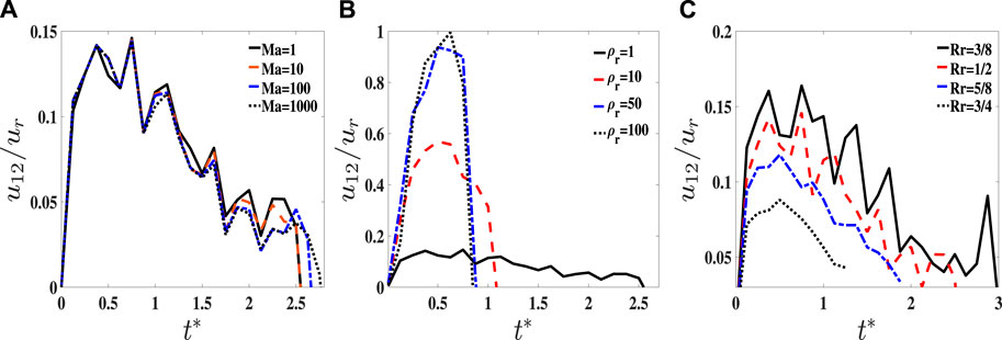
FIGURE 15. Relative migration velocity u12 between the inner and outer droplets versus time t*. (A) Effect of Ma, (B) effect of ρr, and (C) effect of Rr.
In this work, a hybrid ACACE LBM is developed to simulate thermocapillary migration of the hollow droplet with difference in variable fluid properties. The interface interaction between different phases is modeled by a potential formulation of interfacial tension force, and the Marangoni stress is modeled by the concept of continuum surface force. Both forces are included in the Navier–Stokes equations. The evolution of fluid–fluid interface is captured by the conservative Allen–Cahn equation, and the heat transfer in the two-phase system is governed by the convection–diffusion equation. Two LBMs are applied to solve the hydrodynamic and interface capturing equations, respectively, whereas the convection–diffusion equation for determining the temperature field is solved by the isotropic finite difference method for spatial discretization and the second-order Runge–Kutta method for time matching. The model is validated by the stationary droplet at the uniform temperature field and thermocapillary migration of the deformable droplet at the limit of zero Reynolds and Marangoni numbers.
Thermocapillary migration of the hollow droplet with a constant temperature gradient along the x direction is simulated by the present hybrid ACACE LBM, and the influence of Ma number (Ma = 1–1,000), ρr (ρr = 1–100), and Rr (Rr = 3/8–3/4) on the performance of hollow droplet migration is systematically investigated. It is shown that the aforementioned non-dimensional parameters have the effect on thermocapillary migration for the hollow droplet. When Ma is small, the isotherms show the heat transfer takes place through conduction around the hollow droplet. As Ma increases, the heat transfer is changed from conduction to convection around the hollow droplet, whereas the time evolution of d is slowed down in comparison with small Ma. When the density ratio is increased, the isotherms are accumulated around the hollow droplet front with a large temperature gradient, which induces a large driven force for the hollow droplet migration, and the change rate of d is fast at large ρr. On the other hand, the radius ratio of Rr can also affect the hollow droplet migration. It is shown that the interaction between fluid 2 of the hollow part inside the droplet and sealed fluid 1 of the droplet is enhanced with large Rr, and a large amplitude variation in the migration velocity of the hollow droplet is observed with the increase in Rr. The measured time evolution of d demonstrates that the density ratio ρr has a significant influence on the reduction rate of d in contrast to Rr and Ma, and the magnitude of relative migration velocity u12 is obviously affected by ρr and Rr compared to Ma.
The original contributions presented in the study are included in the article/Supplementary Material; further inquiries can be directed to the corresponding author.
XQ: conceptualization, methodology, investigation, data curation, writing—original draft, and writing—review and editing.
This work was supported by the Anhui Provincial Natural Science Research Project of China (Grant Number KJ2021A1032) and the Key Construction Discipline of Chaohu University (Grant Numbers kj22zdjsxk01, kj22yjzx05, and kj22xjzz01).
The author declares that the research was conducted in the absence of any commercial or financial relationships that could be construed as a potential conflict of interest.
All claims expressed in this article are solely those of the authors and do not necessarily represent those of their affiliated organizations, or those of the publisher, the editors, and the reviewers. Any product that may be evaluated in this article, or claim that may be made by its manufacturer, is not guaranteed or endorsed by the publisher.
1. Subramanian RS, Balasubramaniam R. The motion of bubbles and drops in reduced gravity. Cambridge: Cambridge University Press (2001).
2. Darhuber AA, Troian S. Principles of microfluidic actuation by modulation of surface stresses. Annu Rev Fluid Mech (2013) 37:425–55. doi:10.1146/annurev.fluid.36.050802.122052
3. Young NO, Goldstein J, Block M. The motion of bubbles in a vertical temperature gradient. J Fluid Mech (1959) 6:350–6. doi:10.1017/S0022112059000684
4. Balasubramaniam R, Subramanian RS. Thermocapillary bubble migration—Thermal boundary layers for large marangoni numbers. Int J Multiph Flow (1996) 22:593–612. doi:10.1016/0301-9322(95)00075-5
5. Crespo A, Migoya E, Manuel E. Thermocapillary migration of bubbles at large Reynolds number. Int J Multiph Flow (1998) 24:685–92. doi:10.1016/s0301-9322(97)00076-1
6. Nas S, Muradoglu M, Tryggvason G. Pattern formation of drops in thermocapillary migration. Int J Heat Mass Transfer (2006) 49:2265–76. doi:10.1016/j.ijheatmasstransfer.2005.12.009
7. Tryggvason G, Bunner B, Esmaeeli A, Juric D, Al-Rawahi N, Tauber W, et al. A front-tracking method for the computations of multiphase flow. J Comput Phys (2001) 169:708–59. doi:10.1006/jcph.2001.6726
8. Yin Z, Chang L, Hu W, Li Q, Wang H. Numerical simulations on thermocapillary migrations of nondeformable droplets with large marangoni numbers. Phys Fluids (2012) 24:092101. doi:10.1063/1.4752028
9. Yin Z, Li Q. Thermocapillary migration and interaction of drops: Two non-merging drops in an aligned arrangement. J Fluid Mech (2015) 766:436–67. doi:10.1017/jfm.2015.10
10. Balcazar N, Rigola J, Castro J, Oliva A. A level-set model for thermocapillary motion of deformable fluid particles. Int J Heat Fluid Flow (2016) 62:324–43. doi:10.1016/j.ijheatfluidflow.2016.09.015
11. Samareh B, Mostaghimi J, Moreau C. Thermocapillary migration of a deformable droplet. Int J Heat Mass Transfer (2014) 73:616–26. doi:10.1016/j.ijheatmasstransfer.2014.02.022
12. Haj-Hariri H, Shi Q, Borhan A. Thermocapillary motion of deformable drops at finite Reynolds and Marangoni numbers. Phys Fluids (1997) 9:845–55. doi:10.1063/1.869182
13. Guo Z, Lin P. A thermodynamically consistent phase-field model for two-phase flows with thermocapillary effects. J Fluid Mech (2015) 766:226–71. doi:10.1017/jfm.2014.696
14. Liu H, Valocchi AJ, Zhang Y, Kang Q. Phase-field-based lattice Boltzmann finite-difference model for simulating thermocapillary flows. Phys Rev E (2013) 87:013010. doi:10.1103/PhysRevE.87.013010
15. Liu H, Wu L, Ba Y, Xi G. A lattice Boltzmann method for axisymmetric thermocapillary flows. Int J Heat Mass Transfer (2017) 104:337–50. doi:10.1016/j.ijheatmasstransfer.2016.08.068
16. Huang JX, He K, Wang L. Three-dimensional study of double droplets impact on a wettability-patterned surface. Comput Fluids (2022) 248:105669. doi:10.1016/j.compfluid.2022.105669
17. Gulyaev I, Solonenko O. Hollow droplets impacting onto a solid surface. Exp Fluids (2013) 54:1432. doi:10.1007/s00348-012-1432-z
18. Kumar A, Gu S, Kamnis S. Simulation of impact of a hollow droplet on a flat surface. Appl Phys A (2012) 109:101–9. doi:10.1007/s00339-012-7043-y
19. Kumar A, Gu S. Modelling impingement of hollow metal droplets onto a flat surface. Int J Heat Fluid Flow (2012) 37:189–95. doi:10.1016/j.ijheatfluidflow.2012.06.004
20. Kumar A, Gu S, Tabbara H, Kamnis S. Study of impingement of hollow ZrO2 droplets onto a substrate. Surf Coat Technol (2013) 220:164–9. doi:10.1016/j.surfcoat.2012.08.061
21. Li DS, Duan XL, Zheng ZW, Liu YS. Dynamics and heat transfer of a hollow droplet impact on a wetted solid surface. Int J Heat Mass Transfer (2018) 122:1014–23. doi:10.1016/j.ijheatmasstransfer.2018.02.017
22. Li DS, Zhang D, Zheng ZW. Numerical analysis of hollow droplet impacts on a dry flat surface. Int J Heat Mass Transfer (2019) 129:753–63. doi:10.1016/j.ijheatmasstransfer.2018.09.063
23. Nasiri M, Amini G, Moreau C, Dolatabadi A. Hollow droplet impact on a solid surface. Int J Multiph Flow (2021) 143:103740. doi:10.1016/j.ijmultiphaseflow.2021.103740
24. Naidu DP, Dash S. Impact dynamics of air-in-liquid compound droplets. Phys Fluids (2022) 34:073604. doi:10.1063/5.0096599
26. Lee T, Lin CL. A stable discretization of the lattice Boltzmann equation for simulation of incompressible two-phase flows at high density ratio. J Comput Phys (2005) 206:16–47. doi:10.1016/j.jcp.2004.12.001
27. Guo ZL, Han HF, Shi BC, Zheng CG. Theory of the lattice Boltzmann equation: Lattice Boltzmann model for axisymmetric flows. Phys Rev E (2009) 79:046708. doi:10.1103/PhysRevE.79.046708
28. Zheng L, Guo ZL, Shi BC, Zheng CG. Kinetic theory based lattice Boltzmann equation with viscous dissipation and pressure work for axisymmetric thermal flows. J Comput Phys (2010) 229:5843–56. doi:10.1016/j.jcp.2010.04.026
29. Zheng L, Guo ZL, Shi BC, Zheng CG. Lattice Boltzmann equation for axisymmetric thermal flows. Comput Fluids (2010) 39:945–52. doi:10.1016/j.compfluid.2010.01.006
30. Zheng L, Zheng S, Zhai QL. Reduction-consistent axisymmetric lattice Boltzmann equation method for N-phase fluids. Comput Fluids (2021) 218:104857. doi:10.1016/j.compfluid.2021.104857
31. Liu H, Valocchi AJ, Zhang Y, Kang Q. Lattice Boltzmann phase-field modeling of thermocapillary flows in a confined microchannel. J Comput Phys (2014) 256:334–56. doi:10.1016/j.jcp.2013.08.054
Keywords: axisymmetric lattice Boltzmann method, Allen–Cahn equation, continuous surface force, hollow droplet, thermocapillary migration
Citation: Qin X (2023) A hybrid axisymmetric conservative phase-field lattice Boltzmann method for hollow droplet migration. Front. Phys. 11:1230299. doi: 10.3389/fphy.2023.1230299
Received: 28 May 2023; Accepted: 26 June 2023;
Published: 13 July 2023.
Edited by:
Song Zheng, Zhejiang University of Finance and Economics, ChinaReviewed by:
Lei Wang, China University of Geosciences Wuhan, ChinaCopyright © 2023 Qin. This is an open-access article distributed under the terms of the Creative Commons Attribution License (CC BY). The use, distribution or reproduction in other forums is permitted, provided the original author(s) and the copyright owner(s) are credited and that the original publication in this journal is cited, in accordance with accepted academic practice. No use, distribution or reproduction is permitted which does not comply with these terms.
*Correspondence: Ximei Qin, cWlueGltZWkyMDIxQDE2My5jb20=
Disclaimer: All claims expressed in this article are solely those of the authors and do not necessarily represent those of their affiliated organizations, or those of the publisher, the editors and the reviewers. Any product that may be evaluated in this article or claim that may be made by its manufacturer is not guaranteed or endorsed by the publisher.
Research integrity at Frontiers
Learn more about the work of our research integrity team to safeguard the quality of each article we publish.