
95% of researchers rate our articles as excellent or good
Learn more about the work of our research integrity team to safeguard the quality of each article we publish.
Find out more
ORIGINAL RESEARCH article
Front. Phys. , 08 September 2023
Sec. Optics and Photonics
Volume 11 - 2023 | https://doi.org/10.3389/fphy.2023.1225462
Abstract
Polarisation states are described by spin expectation values, known as Stokes parameters, the trajectories of which in a rotationally symmetric system form a sphere named after Poincaré. Here, we show that the trajectories of broken rotational symmetric systems can exhibit distinct topological structures in polarisation states. We use a phase-shifter to form a polarisation circle
Topology and quantum mechanics are inherently connected, and various exotic phenomena, such as the quantum Hall effect [1–6], spin Hall effect [7–9], topological insulator [10–14], and topological photonics [15–19], were predicted theoretically [1, 2, 4–8, 11, 12, 15] and discovered experimentally [3, 9, 13, 16, 17]. These topological orders [4–6, 10, 20–25] are different from thermodynamic spontaneous symmetry-breaking such as a superconducting phase-transition [23, 24, 26–30], which is characterised by opening an energy gap in the excitation spectrum to establish a long-range order [30–32], while electronic or photonic states have a continuous spectrum in a vacuum with full translational, time-reversal, and rotational symmetries [26–30, 33–35]. In a topological material [1, 2, 4–6, 8, 11, 12, 15, 36], an energy gap is formed in the bulk as an insulator, which has a different symmetry from that in a vacuum, such that the energy gap must be closed at the edge, the state of which is topologically protected against structural imperfections as a highly conductive metal to accommodate massless Dirac fermions [4–6, 22]. This bulk-edge correspondence [4–6, 22] is considered to be a generic feature of topological materials, the topological invariants of which are Chern numbers [37], obtained by integrating the Pancharatnam–Berry geometrical phase [38–41] of wavefunctions over the Brillouin zone [14, 42–44]. Thus, topological materials have unique topological band structures in the momentum space [14, 42, 43], rather than topological bonding configurations in the real space [45–55].
Here, we explore topological features in the polarisation space for spin states of coherent photons; that is, we consider topological aspects of polarisation states. The polarisation state is described by an SU(2) state, known as a Jones vector, which is a wavefunction of the spin state of photons [56–82]. The wavefunction obviously has the amplitude and the phase, which are described by the polar angle (θ) and the azimuthal angle (ϕ), respectively, to show the average spin values as a vector to represent the state on the Poincaré sphere [56–82]. In fact, we have recently demonstrated to realise an arbitrary polarised state by passive [81] and active [82] Poincaré rotators to execute an SU(2) rotation of the Lie groups [83–88] in the combination of a U(1) phase-shifter and a rotator. While considering the coherent polarisation state in the power normalised configuration space, the Poincaré sphere can be used with a unit radius (r) [60–62]. The Poincaré sphere with r = 1 is equivalent to the Bloch sphere [72, 74, 81, 82, 89, 90], which means that trajectories of the polarisation states upon controlling the amplitude and the phase form a two-dimensional (2D) sphere (
However, there is one noticeable difference between Poincaré and Bloch spheres, i.e., the Bose–Einstein and Fermi–Dirac statistics for photons and an electron, respectively [23, 24, 61–63, 72–75, 78, 82, 91]. For photons, we can generate another photon with the same phase as that of an original photon via the stimulated emission process by using a polarisation-independent Er-doped fibre amplifier (EDFA) [60–67, 75, 78, 82]. This corresponds to an increase r without changing the angles of θ and ϕ, which is impossible to achieve for an electron due to the Pauli exclusion principle [92, 93]. The stimulated emission process requires a finite pumping power for the amplification, such that the process is not based on the norm-conserving unitary transformation [60, 63, 82]. Therefore, the amplification of coherent photons does not violate the no-cloning theorem [92, 93], which prohibits copying of a quantum state by a unitary transformation, because the prerequisite of the notion for non-cloning is not satisfied by the injection of the pumping power. Consequently, we consider a larger polarisation space, where the radius of the Poincaré sphere is not restricted to be unity, but the polar coordinate of (r, θ, ϕ) could span for the full 3D Euclidean space of Stokes parameters S = (S1, S2, S3), which we term as the Stokes space. In the Stokes space, points with different r can be distinguishable, even if θ and ϕ are the same. This is not surprising because we are dealing with signals with different intensities as for the means of digital communications [60, 94–96], such as quadrature amplitude modulation (QAM), pulse amplitude modulation (PAM) for advanced multiplexing, and dual-polarisation quadrature-phase-shift-keying (DP-QPSK) [97, 98]. Stokes parameters [60–62] can be described by energy per bit (pJ/bit) or power (mW). Alternatively, they are also equivalent to the spin expectation values [75, 77], which are obtained by the Dirac constant of ℏ (the Planck constant of h, divided by 2π), multiplied with the number of photons per second, passing through the area perpendicular to the direction of the propagation, with the spin pointing towards x, y, and z directions, respectively. In this paper, we use power for the dimension of Stokes parameters for simplicity. In the Stokes space, considering the difference in intensities, we can explore topologically non-trivial trajectories for the pulse streams generated from a device with broken rotational symmetries in polarisation states.
As an example of non-trivial polarisation state in the Stokes space, we first describe how to realise a polarisation torus,
We consider the propagation of light in a single-mode fibre (SMF), such that only the fundamental spatial mode of a SMF is available [60]. It is also important to make sure that the coherence of the wave is maintained upon separating the wave and combining the waves for the interference. We have recently revisited the theoretical description [75, 78, 81, 82] for the coherent state of photons, emitted from a laser source, and confirmed that it should be treated as a many-body coherent state with the SU(2) degrees of freedom for polarisation [58–62, 68–74, 91]. The coherent state [63, 67, 75, 81, 82, 91] is characterised by the Gaussian distribution of the photon number, centred at the average number of photons per second,
is enough to characterise the polarisation state on the Poincaré sphere [56–82], where Φ is the U (1) phase of the orbital wavefunction, γ = 2α is the polar angle measured from S1, δ is the phase-shift measured from S2, and α is the auxiliary angle for complex electric fields. Here, we have used horizontal (H) and vertical (V) bases as for the fundamental states to describe the polarisation, and the normalisation of the wavefunction (N) is related to the power intensity of the ray as P = ℏωN = S0, where ω is the angular frequency and S0 is the 0-th component of the Stokes parameter. The SU(2) nature of the polarisation is not affected by this normalisation, and it is straightforward to obtain the spin expectation values for photons as
where the spinor vector of
forming the Lie algebra of
in the unit of mW. Alternatively, we can consider a normalisation based on the power as
which we will employ, henceforth.
The exponential map [83–88] from the Lie algebra of
where
Historically, it was theoretically proven that three waveplates are enough to realise an arbitrary polarisation state [68–70], as demonstrated by an SU(2) gadget [100, 101]. We have recently demonstrated that four waveplates are easier to realise an arbitrary phase-shift solely by rotating one of the waveplates [81]. This corresponds to realise an SU(2) rotation of the wavefunction of |P, γ, δ⟩ and the physical observable of
Here, we consider using another degree of freedom together with SU(2) degrees of freedom, which is the U(1) phase of Φ = kz − ωt + Φ0 for the orbital degree of freedom, where k = 2π/λ is the wavenumber for the wavelength of λ, z is the direction of the propagation along the SMF, and Φ0 is the initial phase. The U(1) phase plays no role, if we take the quantum average of spin states, as shown previously, since it merely changes the global phase of the wavefunction. On the other hand, if we have another wave to compare the relative phase, the U(1) phase could play a significant role. For photons, this could be achieved simply by splitting the wave into two (or more) waves and introducing the relative phase change and recombining to allow the interferences. The U(1) phase is related to the number of photons, such that the interference induces changes in the number of photons, propagating to the SMF after the interference. This process allows controlling P (or equivalently N), which corresponds to change in the radius of the Poincaré sphere. There are several schemes to introduce the phase changes, and we consider one of the most simplest one, which just introduces the SU(2) operation to one of the waves. The SU(2) operation introduces the U(1) phase change, which is observable upon interferences. For example, one rotation on the Poincaré sphere of SO(3) induces the sign change of the SU(2) wavefunction because we expect
which induces the destructive interference to the original input wave. Mathematically, this results from the double covering of SU(2) to SO(3), which is described as
We explain the simple method to change the polarisation state together with the intensity in the Stokes space. We assume specific experimental parameters to make the argument easy to understand, but it is straightforward to change parameters and to construct more generic theories. First, we prepare the input wave with the power of Pin = 1.5 mW with the diagonally (D) polarised state, such that the input state of |Input⟩ is prepared as
Then, we split the input wave into two waves by using a polarisation-independent directional fibre-to-fibre coupler (FFC). We used the FFC of the splitting ratio of 90:10, which means that 90% of the signal is transmitted to the through port 3 and 10% is coupled to the tap port 4, when we inserted from the input port 1, while the isolated port 2 is not used. We define the coupling constant of α = 0.1 to account for the FFC, and the splitting is simply defined by a matrix operation,
where two components of polarisation states |Pin, π/2, 0⟩ is used for |Port 1⟩, and |Port 2⟩ is 0 = (0,0)t, where t stands for the transpose of the vector. The output from the tap port 4 is used to manipulate its polarisation state by a phase-shifter,
which is the rotation along S1 in the S2–S3 plane [81]. We defined the rotation angle of δϕp since this corresponds to the rotation along the poloidal direction, as we shall see as follows. We have previously shown that we can construct a passive phase-shifter by a combination of two quarter-wave plates (QWPs) and two half-wave plates (HWPs) [81]. The amount of rotation in SO(3) is determined by the physical angle of the rotation (δΨp) of one of the HWPs as δϕp = 4δΨp [81]. Then, the output state of the tap port 4 becomes
while the output from the through port 3 is preserved to keep its polarisation state as |Port 3′⟩ = |Port 3⟩. Then, we recombine the through port 3 and tap port 4 by the inverse arrangement,
to expect that the port 1′ is the main output, while the port 2′ is not used. Finally, the spin expectation values of |Port 1′⟩ are calculated, as shown in Figure 1.
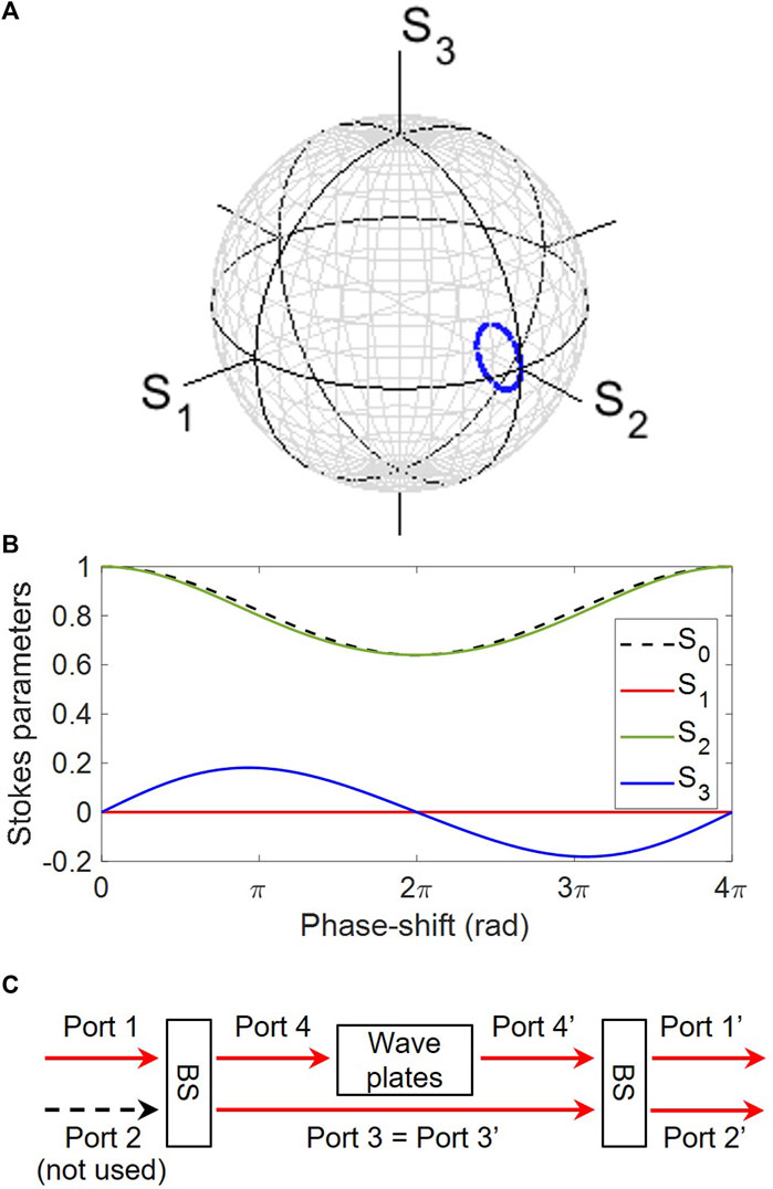
FIGURE 1. Calculated trajectories of polarisation states for the output from a polarisation interferometer. The input state is prepared to be a diagonally polarised state at S2 = 1.0 on the normalised Poincaré sphere. (A) Stokes parameters, showing a polarisation circle (blue), which reduces its intensity upon the rotation. (B) Stokes parameters against the phase-shift by an SU(2) phase-shifter. The 2π-rotation minimises the intensity in the diagonally polarised state, and the 4π-rotation is required to come back to the original input state. (C) Schematic diagram of polarisation interferometer. The operation principle is based o the interference between beams with and without the phase-shift during the propagation.
We confirmed that the polarisation states are mostly located near the diagonally polarised state, |D⟩ since we assumed 90% of the input for the through port 3 is preserved. Without the phase-shift of the tap port 4, we confirmed that the polarisation state and the intensity are not affected by the input state. On the other hand, if we closely look at the circular trajectory, we confirm that the trajectory is inside the original Poincaré sphere, which means that the radius, corresponding to the intensity, is successfully decreased. The reduction in energy is confirmed in S0 (Figure 1B), which becomes minimum at δϕp = 2π for the rotation of the tap port 4, where the polarisation state is purely diagonally polarised. This results from the double covering of SU(2) to SO(3), discussed previously [75]. The circular rotation means that the input state of |D⟩ returns to the original state in the SO(3) space; however, in the real physical space, it is enough for the complex electric field for the linearly polarised diagonal state to rotate only for the rotation angle of π to become the diagonal state upon the rotation. This means that the electric field will be flipped to change the sign, which is not visible on the original Poincaré sphere. On the other hand, this sign change is observable by using the portion of the original input wave, which is the role of the transmitted wave through port 3. The destructive interference becomes maximum at δϕp = 2π, yielding the minimum of S0. The entire trajectory requires the 4π-rotation to close, as expected for the SU(2) group, and it became a polarisation circle
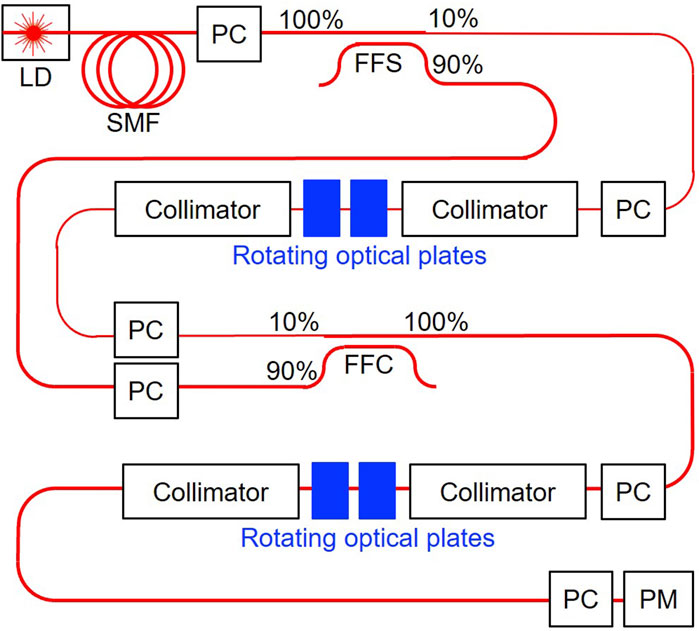
FIGURE 2. Polarisation interferometer to realise topologically non-trivial polarisation states in the Stokes space. Rotating optical plates were used to change the spin states of SU(2) as well as the orbital U(1) phase for the bypassed wave. These phase changes are observed upon interferences with the preserved input states, thus allowing changes in intensities for the output state. Abbreviations are as follows: LD, laser diode; SMF, single-mode fibre; PC, polarisation controller; FFS, fibre-to-fibre splitter; PM, polarimeter.
We acquire a scheme to control the radius of the polarisation states, simply by mechanically rotating a HWP, which corresponds to the change in the intensity. The total energy must be conserved upon the linear operations, and the reduced intensity exits from the isolated port 2′, which is terminated. Consequently, the output intensity from the output port 1′ could be reduced upon addition to our polarisation interferometer. Thus, if we focus on the output waves, the system is not only based on unitary operations but also allows a loss mechanism to reduce the radius, the direction of which is perpendicular to the surface of the sphere along polar and azimuthal directions, controlled by θ and ϕ for the polar coordinate or by γ and δ in the HV bases. In this sense, our system is non-Hermitian, and the original rotational symmetry of the polarisation state is also broken to expect a loss in a particular direction. In this way, we obtain a method to potentially scan an entire Euclidean coordinate in the Stokes space inside the original Poincaré sphere, spanned by the radius of the input wave. Due to the 3D nature of the Stokes space, we can consider various topologically non-trivial structures, which we will explore as follows.
As the first non-trivial topological structure of polarisation states, we explain how to construct a polarisation torus as a set of polarisation states in the Stokes space. In topology, a torus is made of
where δϕt is the amount of rotation along the toroidal direction to the poloidal polarisation circle. We have previously shown that two successive operations of HWPs are equivalent to a proper rotator operation to form the SO(2) group [81] rather than a pseudo-rotator realised by one rotated HWP [60–62], and we just need to mechanically rotate one of the HWP to realise the target amount of rotation along the S3 axis (the last part of rotating optical plates in Figure 2). The output polarisation state after the operation becomes
and we can finally calculate the Stokes parameters from this output state (Figure 3).
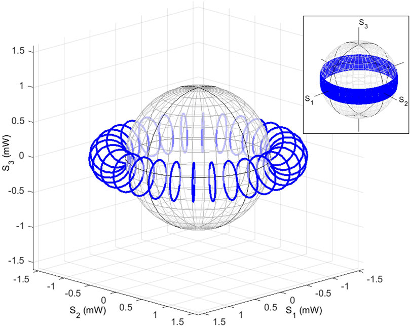
FIGURE 3. Construction of the polarisation torus calculated in the Stokes space. The intensity of the input state in the diagonally polarised state with the power of 1.5 mW was interfered in the polarisation interferometer to form a small circle in the S2 − S3 plane along the poloidal direction. Then, a rotator was used to rotate the circle in the S1 − S2 plane along the toroidal direction. The inset shows the same trajectories, shown on the Poincaré sphere.
We confirmed that the calculated vectorial components of Stokes parameters form a polarisation torus (Figures 4A–C), and the intensities of the output satisfy
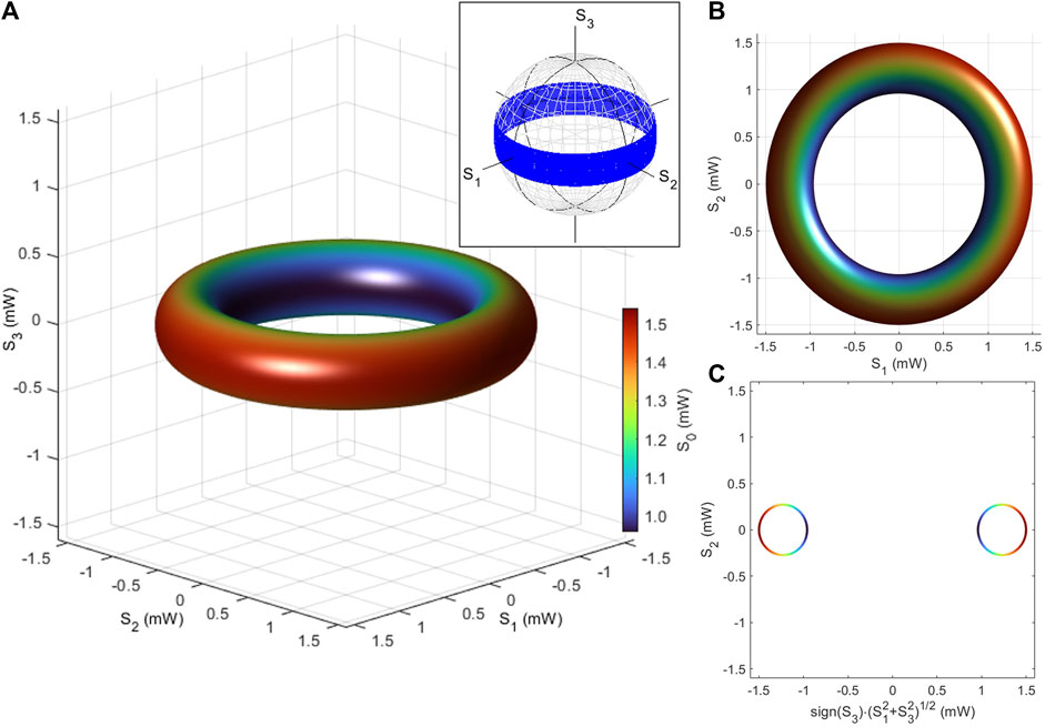
FIGURE 4. Polarisation torus in the Stokes space. The input state to the polarisation interferometer is in the diagonally polarised state with a power of 1.5 mW. The output power is controlled upon the interference, together with the polar angle and the phase, affected by rotating waveplates. The Stokes parameters, (S0, S1, S2, S3), of output states were calculated by using a simple representation theory of U(2) ≅ U(1) × SU(2). (A) Stokes parameters are shown for various poloidal and toroidal rotation angles. (B) Toroidal states, seen from the top of the S3 axis. (C) Poloidal states, as a cross-section of the torus, perpendicular to the toroidal plane. The inset shows the polarisation torus collapsed on the Poincaré sphere. The calculated Stokes parameters for the polarisation torus were mapped onto the Poincaré sphere after the normalisations at each point. The torus becomes a belt with no information of the intensity on the Poincaré sphere.
We have also plotted the calculated Stokes parameters on the Poincaré sphere after normalisation at each output state (the inset of Figure 4A). In this case, we cannot discuss differences in relative intensities, and the trajectories of the torus collapsed to form a belt on the Poincaré sphere with no width. The mapping corresponds to a projection from
As shown in Figures 5A–F, we have also calculated the polarisation torus by using the rotated QWP as the final rotation in Figure 2 instead of the rotator. In this case, the trajectories by a rotated QWP for the input of the D-state assume an “8”-like structure with two holes [81], such that the rotation of the polarisation circle of Figure 1A upon the rotated QWP forms two toruses (Figure 5A). Unfortunately, this structure is not a torus of g = 2, but it is simply two toruses of g = 1 overlapping each other, since the simple moves of the circle intersect near the D-state. As shown in Figure 5C, the trajectories have cross-sections, such that the topological feature is closed. In order to claim that the structure is a torus of g = 2, the inside of the structure must be a complete hollow without intersections. By introducing an ellipticity for the input polarisation state, we can introduce the asymmetry for the “8”-like structure (Figure 5B) with a larger hole and a smaller hole [70]. However, this asymmetry also has intersections to separate the hollows. Nevertheless, closed links, made by trajectories of polarisation states, are located on the surface of the torus (g = 2) without intersections, as shown in Figures 5D, E. Figure 5D was drawn for four values of the phase-shifters, while the QWP was fully rotated for each link. In experiments, we have confirmed the trajectories of Figure 5D for the input of the diagonally polarised state. Figure 5E was obtained by gradual rotations of QWP while phase-shifting at the interferometer. In this example, 25 rotations were made by phase-shifters to rotate the torus of g = 2, locally long the poloidal direction, while the entire link is closed at the diagonally polarised state. Similarly, we can realise a trefoil knot [55, 102, 103] by closing the link on the surface of the torus (g = 1), while phase-shifting in the interferometer (Figure 5F).
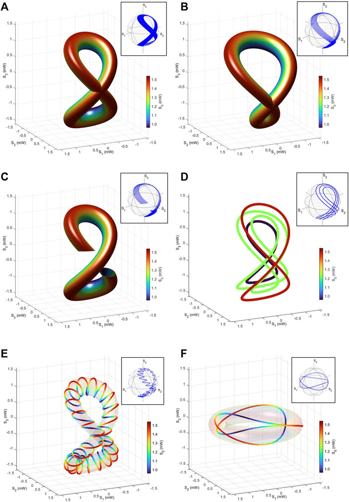
FIGURE 5. Coupled polarisation torus. Stokes parameters were calculated, using a rotated quarter-wave plate, applied to a polarisation circle. Two holes are visible, but the structure is based on two connected toruses with the genus of 1. Trajectories of polarisation states for the input of (A) diagonally linear polarised states and (B) elliptically polarised state at α = π/4 and δ = π/8. Symmetric trajectories showing a character of 8 are shown in (A), while asymmetric trajectories are shown in (B). (C) Approximately 80% of drawing for trajectories of (A) to show just before the intersections. Due to the intersections, the topology of (A) cannot be a torus of g = 2. (D) Trajectories of (A) for fewer parameters at the interferometer. (E) Trajectories of polarisation states by combining phase-shifts and rotations of quarter-wave plates at the same time to allow 25 rotations. The connected link covers the torus of g = 2. (F) Trefoil knot by using a half-wave plate, instead of a quarter-wave plate. The trefoil knot covers the torus of g = 1. The insets show the trajectories of polarisation states on the Poincaré sphere.
Our experiments were conducted in a fibre-based system, together with short-distance free space optics, as shown in Figure 2. A frequency-locked distributed-feedback (DFB) laser diode (LD) with a wavelength of 1533 nm was used and coupled to a SMF. The polarisation of the input wave was adjusted to the D-state by a birefringent polarisation controller (PC), and the input power was 1.8 mW. Then, the input wave was inserted into the polarisation interferometer, as explained previously, with 2 FFSs and rotating optical plates, and the output from the interferometer was further controlled by the next rotating optical plates. At each step, the polarisation states of the fibre were adjusted by PCs, and the final output wave was examined by a polarimeter to observe the Stokes parameters [81].
The experimental Stokes parameters are shown in Figure 6. We have set δϕp at 0, π, 2π, and 3π, which corresponds to the rotation of HWP δΨp at 0, π/4, π/2, and 3π/4, respectively. At each δϕp, we have mechanically rotated the HWP of the rotator to change δϕt and obtained the trajectories by recording the Stokes parameters using PM, while rotating physically. As expected, from the proper rotator operation of two successive operations of HWPs to form SO(2) [81], each trajectory is a circle, located parallel to the S1–S2 plane (Figure 6B). On the other hand, the change in δϕp corresponds to the rotation along the poloidal direction, and the intensity has been changed upon the interference, which is confirmed by the small empty region in the cross-section of the torus (Figure 6C). The maximum output power was 1.5 mW, such that the minimum insertion loss was about 0.8 dB, and the overall feature of the observed polarisation torus is in reasonable agreement with the calculated results (Figure 3).
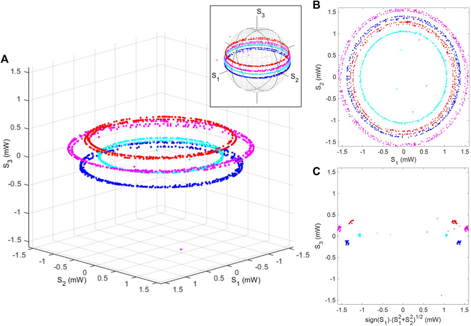
FIGURE 6. Polarisation torus in the Stokes space. Stokes parameters for coherent photons out of the polarisation interferometer were plotted. After setting the poloidal rotation angle, four trajectories (red, magenta, blue, and cyan in colours) were obtained at each angle by mechanically rotating the half-wave plate to change the toroidal angle. Stokes parameters are shown (A) in the 3D Stokes space, (B) from the top of the S3 axis, and (C) as a cross-section perpendicular to the toroidal plane. The insets show the trajectories of polarisation states on the Poincaré sphere.
Now, we can provide more details on the realisation of the polarisation torus based on the U(2) theory along with our experimental preparations of HWPs and QWPs. We explain the free space operations in the polarisation interferometer of Figure 2. We specify the alignment of these waveplates by the angle of the fast axis (FA), measured from the horizon seen from the detector side (opposite to the LD source side) of the plates [75, 81]. In our convention, we assume that the angle is 0, if the FA is aligned horizontally, and equivalently, the slow axis (SA) is aligned vertically, and the direction of rotation is positive, if it is rotated anti-clock-wise, as seen from the top of the detector side. The first free space operations were conducted by a sequential application of QWP (whose FA is aligned to −pi/4), HWP (aligned horizontally), HWP (rotated δΨp), and finally QWP (whose FA is aligned to pi/4), and these operations are given by
whose operations are equivalent to
Similarly, the second free space operation can be decomposed into two sequential operations of the HWP (aligned horizontally) and HWP (rotated δΨt),
to realise the proper SO(2) rotation [81] by
A torus is obviously a topological structure, such that it is expected that the topological structure is strong against distortions. As the first step to confirm the topological robustness, we have inserted the additional QWP with its FA rotated π/4 towards the end of the device, such that the output becomes
which means that the polarisation states should be rotated along the S2 axis with the amount of π/2, and consequently, the S1–S2 plane is rotated to be the S2–S3 plane. The experimental results on the rotated torus are shown in Figure 7. We confirmed that the structure of the torus remained unchanged in the Stokes space upon the rotation, while the toroidal direction is now located parallel to the S2–S3 plane.
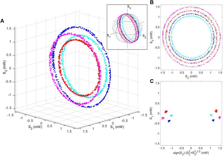
FIGURE 7. Rotated polarisation torus. The quarter-wave plate, whose fast axis was aligned to the diagonal direction, was inserted. Stokes parameters are shown (A) in the 3D Stokes space, (B) from the top of the S3 axis, and (C) as a cross-section, perpendicular to the toroidal plane. We confirmed that the torus was rotated π/2, such that the toroidal direction is parallel to the S2–S3 plane. The inset shows the trajectories of polarisation states on the Poincaré sphere.
Similarly, we have also confirmed that the rotation along the S1 axis preserves the topological structure of the torus. This was realised by adding the QWP with its FA aligned horizontally, and the expected output state becomes
and the experimental results are shown in Figure 8. In this case, the principal axis of the toroidal rotation is along the S2 axis, which is orthogonal to the axes of previous toruses (Figures 6, 7). Therefore, the torus was not distorted upon the applications of rotated QWPs.
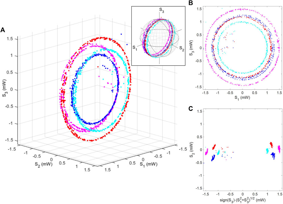
FIGURE 8. Rotated polarisation torus. The quarter-wave plate, whose fast axis was aligned horizontally, was inserted. Stokes parameters are shown (A) in the 3D Stokes space, (B) from the top of the S3 axis, and (C) as a cross-section, perpendicular to the toroidal plane. We confirmed that the topological structure of the torus was not changed upon the rotation. The inset shows the trajectories of polarisation states on the Poincaré sphere.
Theoretically, the phase-shifter and the rotator merely rotate Stokes parameters upon the application of
We have also tried to realise the double-connected toruses with g = 1 by a rotated QWP. Here, we expect the output state of
which makes two connected toruses. The corresponding experimental results are shown in Figure 9. This corresponds to the theoretical calculations of Figure 5D. As shown by the colour difference of Figure 5D, the intensities of each trajectory are different, meaning that the trajectories are not intersecting at the D-state, and therefore, the trajectories are located on the surface of the torus of g = 2. If we increase the number of steps for the poloidal control apart from 4 (Figure 9), the trajectories will be eventually filled, as we have discussed for Figures 5A–C. In order to overcome the closure of the surface, the linked trajectory to cover the surface of the torus of g = 2 (Figure 5E) is required. In our current experimental setup, it was difficult to confirm the trajectory of Figure 5E since we needed to manually rotate the waveplates physically, such that it was tough to allow correlated simultaneous rotations for both poloidal and toroidal directions. In order to allow these experiments, we need dynamic control of polarisation states by optical modulators. We are developing a dynamic polarisation controller by using an LiNbO3 optical modulator [82]. It will be possible in the future to allow the complicated polarisation control by combining the proposed polarisation interferometer together with the dynamic Poincaré rotator.
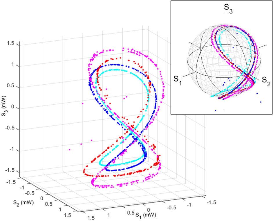
FIGURE 9. Double-connected toruses. The polarisation states were made by operating the states by using a rotated quarter-wave plate at the end of the polarisation interferometer. The sets are made of two connected toruses with the genus of 1. The inset shows the trajectories of polarisation states on the Poincaré sphere.
We have shown polarisation torus is realised experimentally in the Stokes space, where each point represents the spin expectation value of photon coherent states. The observed polarisation states are standard coherent states, but the entire trajectories, realised by the polarisation interferometer, were topologically non-trivial, characterised by g = 1, and the topological states are stationary and stable over time. In our experimental setup, using waveplates, a dynamic control is difficult to achieve, limited by the mechanical rotations of waveplates. On the other hand, there are several exciting achievements to realise topologically non-trivial pulses of lights [99, 104, 105]. The toroidal pulse shape observed by Zdagkas et al. was realised by a tailored manipulation of the meta-surface [99]. Wang et al. realised the micro-cavity in the shape of a Möbius strip to find the notable impact of the Pancharatnam–Berry phase [104]. Li et al. realised a Möbius fibre ring laser to find frequency shifts and geometrical phases [105]. These developments are achieved by considering the dynamical evolution of lights rather than stationary polarisation states. Considering these developments, we also think dynamical evolutions are important to consider topological polarisation states. At this moment, we are developing polarisation modulators to manipulate polarisation states, dynamically [82]. It is also important to see the dynamical response of polarisation states because it is not easy to stabilise the phases of polarisation states against local changes of the environment such as ambient temperature and vibrations. Due to these practical disturbances, our experimental realisations of topological polarisation states are limited to toruses, as explained previously. Nevertheless, we can realise other topological non-trivial features as the polarisation states, as theoretically shown in the following section.
We consider how to realise a Möbius strip in the Stokes space. A Möbius strip [41, 44, 48] is made of a strip with the one end, flipped for connecting to the other end. We consider the same setup as that shown in Figure 2, and we just need to change the optical components in the free space regions. For a Möbius strip, we need to prepare a line segment, rather than a circle (Figure 1), prepared for the torus. Such a line segment can be made by the simple phase-shift to the wave out of the tap port 4 by the phase-shift of
After these operations, the bypassed wave should be recombined by the subsequent FFC with the output from the through port 3. The combined wave should be rotated by the final rotator with the amount of δϕt, which is the same operation as that for the torus. The Stokes parameters were calculated from these U(2) wavefunctions, and the trajectories become the polarisation Möbius strip, as shown in Figure 10A. We can recognise a standard feature of a Möbius strip, designed in the Stokes space.
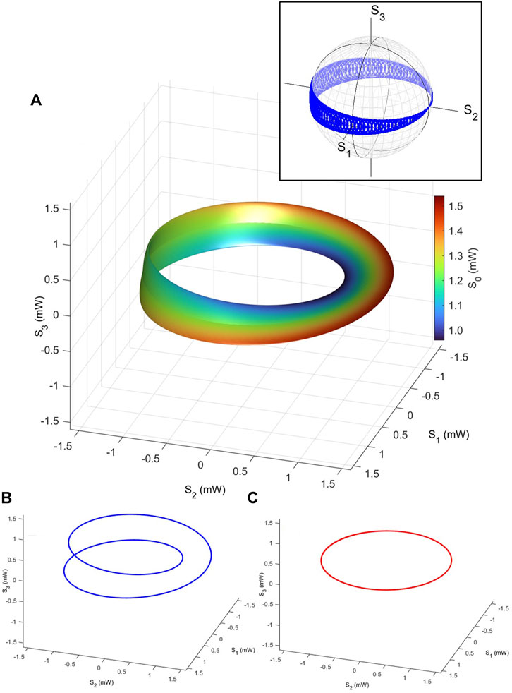
FIGURE 10. Polarisation Möbius strip. Stokes parameters were calculated, assuming the input of 1.5 mW to a polarisation interferometer. A line segment is made of the interference between the bypassed wave with the phase-shift and the original polarisation state at the through port. The segment was rotated by a rotator for the same amount of rotation with the angle for the toroidal rotation. This Möbius strip is right-handed, in the sense that it is made of the line segment, which rotates to the right, seen from the direction opposite to the toroidal rotation. (A) Set of polarisation states in the Stokes space, realised by the polarisation interferometer and rotators. The inset shows the trajectories of polarisation states on the Poincaré sphere. (B) Swapping of the edges of the Möbius strip. A trajectory of polarisation states at the poloidal angle of δϕp = 0 is shown, while the toroidal angle of δϕt was changed from 0 to 4π. The outer edge state becomes the inner edge state, after one rotation, and vice versa, after another subsequent rotation. (C) The centre line of the Möbius strip. A trajectory of polarisation states at the poloidal angle of δϕp = π becomes a polarisation circle, to keep the centre of the Möbius strip, while rotating.
In our original consideration for the torus, we have controlled δϕp from 0 to 4π, while δϕt was changed from 0 to 2π. These parameters also work for the Möbius strip, and this will cover the Möbius strip twice, due to the collapsing of the pore of the torus for the strip. Consequently, the half-rotation for δϕp is enough to realise the Möbius strip. It is even better to consider the quarter-rotation of δϕp from 0 to π, and instead, the double rotation of δϕt from 0 to 4π could be considered. In this case, it is easier to track the trajectory, controlled by δϕt. For example, if we start from the point, realised by δϕp = 0 and δϕt = 0, the original input state is recovered, which is located at the edge of the Möbius strip, and the intensity is maximised. Then, it is easy to see the trajectory (Figure 10B) of showing how δϕt changes the point, moving from the outer edge to the inner edge, and coming back to the original point upon the application of the 4π-rotation. On the other hand, if we start from δϕp = π and δϕt = 0, it is located at the centre of the Möbius strip, and the trajectory becomes the circle upon the change of δϕt from 0 to 2π, and it rotates twice upon the 4π-rotation (Figure 10C).
It is well-known that a Möbius strip cannot be assigned its orientation, which is evident from the fact that we cannot distinguish the front surface from the back surface. On the other hand, we can define its chirality, which depends on how the line segment could be connected upon rotations in our case. The Möbius strip, as shown in Figure 10, is defined to be right-handed because the line segment was rotated to the right side, seen from the direction, opposite to the toroidal rotation. Correspondingly, the left-handed Möbius strip could be considered, simply by the opposite rotation to yield
which was used to calculate its Stokes parameters, as shown in Figure 11. If we focus on the trajectory of the edge, starting from the outer edge at δϕp = 0 and δϕt = 0, polarisation states rotate along the bottom (negative S3), upon the toroidal direction, to arrive at the inner edge, and continue to go up to the top (positive S3), towards going back to the original point. This is the opposite chirality to that of the right-handed Möbius strip, shown in Figure 10. Therefore, the chirality could be controlled, when we realise the Möbius strip by defining the sign of rotation to flip the line segment.
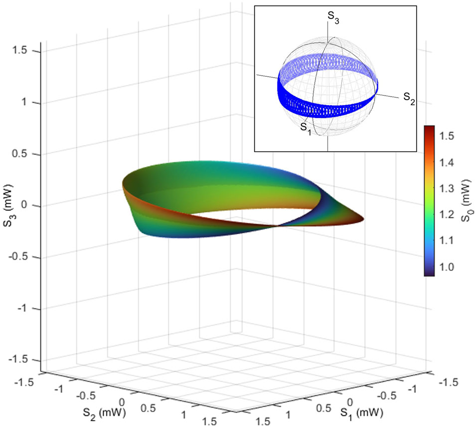
FIGURE 11. Left Möbius strip as polarisation states. Stokes parameters were calculated by considering the rotating segment to the left-handed direction, seen from the direction opposite to the toroidal rotation. The inset shows the trajectories of polarisation states on the Poincaré sphere.
Next, we consider realising a Hopf link using polarisation states. A Hopf link is made of two rings, which are completely disconnected, while one ring intersects with the other (Figure 12). We think it is impossible to realise it solely from 1 wavelength since we cannot allow two different points with different N (or equivalently, P), while keeping the same angles for γ and δ. Therefore, trajectories, controlled by the polarisation states, would be continuous in the Stokes space for 1 wavelength. However, if we allow wavelength-division multiplexing (WDM) in the SMF, we can separately manipulate polarisation states for multiple wavelengths, leading the way to realise optical Hopf links. We just need to adjust relative powers and polarisation states for both wavelengths by considering to establish the topology between two waves.

FIGURE 12. Polarisation Hopf links in the Stokes space. (A) The small circle is calculated for the wavelength of 1530 nm, realised by the polarisation interferometer. The large circle is realised by a phase-shifter for the wavelength of 1550 nm, and these two waves would be combined by a coupler. The inset shows the normalised polarisation states, shown on the Poincaré sphere. The blue (red) circles are for small (large) polarisation circles. (B) Heart-shaped polarisation circle with a Hopf link in the Stokes space. We assumed a 50:50 splitting of the input wave into the polarisation interferometer to realise the heart-like dip near the origin. The inset shows the normalised polarisation states, shown on the Poincaré sphere. The normalised polarisation circle (the blue line in the inset) covers the whole angle in the S1–S2 plane, while the intensity is modulated upon rotations.
As an example, we consider a polarisation circle realised by the polarisation interferometer, shown in Figure 2. Here, we assume 1 wavelength of approximately 1530 nm with the input power of 1.5 mW to be controlled by the polarisation interferometer. The output of the tap port 4 is now controlled as
while we do not need to rotate along the toroidal direction, such that we do not insert any optical components in the second free space region. This will create a polarisation circle in the S1–S2 plane, perpendicular to the direction of S3 (the small circle of Figure 12A). The polarisation circle in the Stokes space is a line segment in the normalised Poincaré sphere (the blue line in the inset of Figure 12A). Next, we just need to prepare another polarisation circle by using a different wavelength of approximately 1550 nm at the power of 1.0 mW, which could be controlled by proposed Poincaré rotators (phase-shifters to control δ) [81, 82], separately, to allow circular changes of polarisation states, located in the S2–S3 plane, perpendicular to the direction of S1 (a large circle of Figure 12A). After constructing these waves in the SMFs, we can combine these by a polarisation-dependent FFC, with an appropriate power splitting ratio. These two polarisation circles do not touch each other in Stokes space, forming a Hopf link (Figure 12). On the other hand, if we plot these states by normalising Stokes parameters to have a unit radius, these two circles are connected (the inset of Figure 12). Therefore, it is important to distinguish the power difference of these waves.
Similarly, we have also calculated a Hopf link by assuming the different ratio of 50:50 (α = 0.5), as shown in Figure 12B, while the other parameters were the same as those for Figure 12A. In this case, the larger polarisation circle is realised upon the interference, due to the larger power, propagating into the tap port 4. As a consequence of the interference, the minimum output power could be 0, which is why the heart-like dip is realised near the origin of the Stokes space.
This heart shape affects the torus structure if the polarisation states are further controlled upon the toroidal rotation, as shown in Figure 13. Here, we have assumed the splitting of 50:50 (α = 0.5) for an input of the single wavelength at 1530 nm with the power of 1.5 mW. We expect that the heart-shaped polarisation circles are making trajectories upon rotations to the toroidal direction, with the amount of δϕt changed from 0 to 3π/2. Due to its feature, we call it a polarisation apple to have seed-like regions due to the heart-shaped dip near the origin. This is a remarkable difference between the mathematical overlapping of two circles upon rotations. In our case, we realise the circular heart-shaped circles upon the interference, such that the intensity near the origin becomes 0 due to the complete destructive interference between two separated waves with the sign change upon the SU(2) rotation.
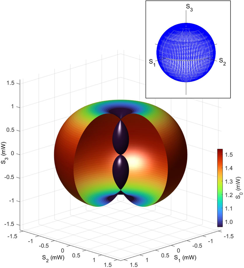
FIGURE 13. Polarisation apple in the Stokes space. The Stokes parameters were calculated for assuming 50:50 splitting at fibre couplers. The toroidal rotations from 0 to 3π/2 (rather than 2π) were assumed to have the seed-like dips near the origin, realised by the interferences. The inset shows the trajectories of polarisation states on the Poincaré sphere.
We have several topologically non-trivial structures as polarisation states in the Stokes space, compared with the Poincaré sphere. Polarisation results from spin expectation values [56–75, 77, 81, 82], such that the non-trivial polarisation states are determined by the broken rotational symmetry for the polarisation states. These topologically non-trivial features are robust against the rotationally symmetric disturbances. For example, the polarisation-independent loss in the SMF cannot change the topology of the polarisation states. Moreover, spherically symmetric operations of phase-shifters and rotators can rotate the topological structures such as toruses (Figures 6–8), Möbius strip (Figures 10, 11), and Hopf links (Figure 12), but still, the relative topology within these structures will be kept upon rotations. It is a polarisation-dependent loss to cut these topological features. Nevertheless, it is not so easy to change the topology since a simple insertion of a polariser, for example, will completely destroy the polarisation structure, ending up to be one point in the Stokes space. We need to make an optical scissor to allow an arbitral cutting of topological polarisation states. In order to reduce the intensity of the targeted polarisation states, we need to observe the polarisation states by using a polarimeter, which corresponds to observing the wavefunctions to expect the collapse of the wavefunction. For coherent photons, we can observe a bypassed contribution via a tap port, while keeping the contribution in the through port [82], but still we need to prepare a complicated photonic circuit to allow the splitting, delay, and manipulation of the loss. These difficulties result from robust correlations among the bits in the pulse stream to form non-trivial topological polarisation states. Here, we discuss how the broken symmetry in the bulk is corresponding to the edge state [4–6, 14, 22, 41–44]. More specifically, we return to the case of the polarisation torus and consider how the polarisation states could be connected to the original Poincaré sphere.
The torus is obviously distinct from the sphere because of the non-zero genus. For the pulse streams of light, coming out of the proposed device, which is the polarisation interferometer with the polarisation rotator (Figure 2), the Stokes parameters of the pulse represent one of the points on the polarisation torus, such that the pulse streams are considered to form the bulk state of the polarisation torus, characterised by g = 1. On the other hand, in the standard SMF with the rotational symmetry, the polarisation states are well-known to be characterised by the Poincaré sphere with g = 0 as a different bulk state. If we would like to connect the torus to the Poincaré sphere, we need to prepare the edge state, where the pore of the torus is closed, such that the polarisation circle (Figure 1A) is closed to be 1 point, which must be robust against disturbances to rotate the polarisation state.
We can generate such an edge state, simply by changing the rotations in the Stokes space. One practical implementation is to use the same setup of Figure 2, while we introduce the amplitude controller,
in the first free space region. The amplitude controller is not a unitary operator, such that this operator does not belong to a family of SU(2). It is an operator of U(2), except for the parameters, δϕp = π, 3π, ⋯, where the operator becomes 0, such that the norm is controlled upon the operation. The amplitude controller is made of polarisation splitters to change the amplitude of each polarisation state, independently, while each polarisation state would be inserted into a polarisation rotator [75, 81, 82] to change its polarisation in the S1-S2 plane, independently, picking up only the original polarisation state after the rotation, and finally recombining orthogonal polarisation states in a combiner. Alternatively, the amplitude controller is simply made of a polarisation-independent Mach–Zehnder interferometer to control the amplitudes for both polarisation components, simultaneously, while keeping the polarisation. The amplitude controller could also be defined as
which accompanies a swapping of the polarisation states in addition to the polarisation rotation.
After the amplitude control of the contribution in the tap port 4, the output polarisation state is further controlled by a QWP, yielding
which is combined with the contribution with the through port 3. Finally, the recombined state is rotated along the S2 axis instead of the S3 axis by the polarisation rotator
These operations will create a topological Dirac cone near the D-state. However, it is intriguing to illustrate it near the north pole (in our convention, the left circularly polarised state [75]), which could be achieved simply by a π/2-rotation along S1. Alternatively, we can apply
to the tap port 4 without a QWP, while the through port 3 is phase-shifted by a QWP to be
and then, the recombined states should be rotated along the S3 axis, just like creating a torus before.
The calculated Stokes parameters in this way are shown in Figure 14, where a topological Dirac cone is recognised in the Stokes space. Bosonic Dirac bosons were previously discussed [106, 107] in realising a single-particle spectrum of a boson. Here, we are not discussing a single-particle energy spectrum in the momentum space. Instead, we are considering the many-body energy (S0) of a bit in a pulse stream, generated from a device, and the change in energy is described against the spin expectation values rather than momentum for an energy band. Due to the coherent nature of bosons with no charge, photons in the same bit do not interact with each other, but the energy difference in S0 could be considered the difference in number of photons in each bit. As shown in Figure 14A, the polarisation circle, generated by a rotator, is closed at the Dirac point, where the light cone is closed. At the Dirac point, the polarisation state is not changed upon rotations along the S3 axis, such that this edge state to close the circle is topologically robust against rotations in the S1–S2 plane. We have also plotted the Dirac cone in the space for (S0, S1, S2), as shown in Figure 14B. We confirmed the linear energy change, seen from S0, against the radius of the polarisation circle in the plane, parallel to the S1-S2 plane. For the constant energy in S0, or equivalently, for the same number of photons in a bit, the bit is characterised in the polarisation circle of the Dirac cone, which changes the helical spin expectation values (S1, S2) upon rotations by a rotator along the S3 axis.

FIGURE 14. Topological Dirac bosons. Stokes parameters (S0, S1, S2, S3) were calculated for the output from the amplitude-controlled polarisation interferometer. (A) Dirac bosons in the vectorial space (S1, S2, S3). The Dirac point at the centre of the light cone is robust against the rotation in the S1–S2 plane, such that a rotator along the S3 axis cannot change the polarisation state at this point. (B) Dirac bosons in the vectorial space (S0, S1, S2). The intensity of the light (S0) is linearly controlled upon the S3 direction, as a result of the interference, while S0 is not affected upon the rotation in the S1–S2 plane, which induces a helical change of the polarisation state. (C) The trajectories of polarisation states are shown on the Poincaré sphere.
If we would like to change g = 1 of a torus to g = 0 of a sphere, it is inevitable to make such a Dirac point, where the polarisation state is robust against the rotations. We think the Dirac point corresponds to the edge state, while the polarisation torus and Poincaré sphere are bulk states. This is the bulk-edge correspondence [4–6, 14, 22, 41–44] for our topological polarisation states.
As an example, we have connected a polarisation torus to a Poincaré sphere via topological Dirac cones, as shown in Figure 15. Here, we have assumed the maximum power of 1.5, 1.05, and 0.75 mW for the polarisation torus, Dirac bosons, and the inner Poincaré sphere, respectively. The number of connected Dirac cones was 4 in this example, but it is not limited to this particular number. The number of edge states simply depended on our experimental setup and feasibility on how to close the pore generated in the torus. In the example of Figure 15A, the torus is continuously connected to four Dirac cones, with four Dirac points to close the pore, and the inner light cone is continuously connected to a Poincaré sphere with a smaller radius (S0). The torus (g = 1) and the sphere (g = 0) describe different bulk states, respectively, while the Dirac points are edge states. Even if we rotate the whole structure in the 3D (S1, S2, S3) space, the topology of these states will not be changed at all, and the polarisation-independent loss merely changes the scale (radius by S0), such that the topology will not be changed, either. Consequently, these topological features in the Stokes space will be robust during the propagation in the SMF, regardless of the polarisation rotations and the loss.
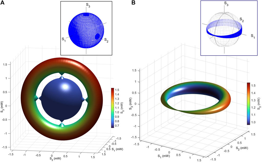
FIGURE 15. Bulk-edge correspondence for topological polarisation states. (A) Stokes parameters were calculated for the torus, Dirac cones, and the Poincaré sphere. The polarisation torus was connected by Dirac cones to the Poincaré sphere. It is inevitable to have a node of the polarisation circle at the Dirac point to change the genus from 1 to 0. (B) Closed polarisation torus. The phase-shift is introduced upon the toroidal rotation, which induces the destructive interference, leading to the Dirac point at the anti-diagonally polarised state. The insets show the trajectories of polarisation states on the Poincaré sphere.
Another method to close the torus is to introduce a phase-shift. For example, we can introduce a phase change upon the toroidal rotation as
which induces the destructive rotation upon the toroidal rotation, leading to a generation of a Dirac point at the diagonally polarised state (Figure 15B). The structure of Figure 15B is not a torus anymore since the pore is closed, but we can introduce the toroidal phase change upon the dynamic operation [82]. Then, the polarisation torus can be dynamically switched to the conventional Poincaré sphere, continuously, along with the time evolution. By considering time as another coordinate, inspired by the time crystal [34, 35], we can dynamically switch polarisation structures with different genera. It is important to recognise that the edge must exist between different topological structures, and in order to close the torus continuously for the sphere, we need at least one Dirac point.
We consider the topological invariance discussed in this paper. In the physics of topological materials, the Chern number [37] is the topological invariance to characterise the non-trivial quantum states. The Chern theorem [37] was established through a generalisation to
First, we evaluated the Chern number for the polarisation torus. To calculate the Chern number, we need to integrate the Pancharatnam–Berry phase of γ along a closed loop. We consider the poloidal rotation, as shown in Figure 2A, whose output state after the polarisation interferometer is given by
for the total rotation of ϕp, and we consider the small deviation of δϕp from ϕp, and the Berry connection [4–6, 38–41, 44] is defined by
which yields the Pancharatnam–Berry phase as
to give the Chern number
which is the winding number for the wavefunction along the closed trajectory in the Hilbert space. We confirmed that the Chern number for the topological torus is 0 upon numerical calculations. This is confirmed on the normalised Poincaré sphere of Figure 4 (and the blue line in the inset of Figure 12A) because the circular rotation in the Stokes space along the radial direction (Figure 2A) simply corresponds to the line integration in the normalised Poincaré sphere, whose solid angle vanishes. Due to the uncertainty of 4π in solid angle and the nature of the 2-level systems, the Chern number of polarisation torus is given by integers
In fact, the topological nature of the polarisation torus is appeared in the Stokes space, where the spin expectation values could take potentially any values in
where K is the product of the minimum and maximum curvatures on the surface and dS is the infinitesimal surface area. For the torus, the curvatures upon the toroidal direction change their sign, such that the integration becomes 0, yielding χ = 0 and g = 1. The values are completely different for a sphere to have χ = 2 and g = 0. Thus, the Euler number and the genus should be appropriate as topological invariants in the polarisation torus. Other topological features are also considered in
We have shown that photons in the coherent states are described by the U(2) wavefunctions, and the spin expectation values, calculated in the wavefunction, span the three-dimensional Euclidean space, named the Stokes space, allowing to realise various non-trivial topological structures rather than the simple Poincaré sphere. We have proposed the polarisation interferometer to realise the polarisation torus and experimentally demonstrated the structure through the polarimetry. We have also shown that other topologically non-trivial structures, such as Möbius strip, Hopf links, and topological Dirac bosons. These topological structures in the Stokes space are characterised by the Euler number and genus rather than the Chern number since the spin expectation values are observable and the proposed topological structures are realised in real values rather than complex values of wavefunctions. We found that a bulk-edge correspondence is applicable to these topological features, and the torus and the sphere must be continuously connected, only when the Dirac point is realised at the edge to connect these structures in the Stokes space. Topological polarisation states are robust against rotations, phase-shifts, and polarisation-independent losses during the propagation in the single-mode fibre, such that these features can be transmitted without breaking topological correlations. The proposed topological structures are supported by the bosonic nature of photons, allowing many photons to occupy the same state, which has a remarkable difference in the fermionic Bloch state. The energy spectrum of proposed Dirac bosons is characterised by these coherent bosons, rather than the single-particle spectrum, and the linear dispersion of the energy in the bit will be observed against the helical polarisation. We think these topological polarisation states are generic features for coherent photons emitted from ubiquitous laser sources, such that we can consider various applications such as robust optical communications and fibre sensors against signal disturbances in harsh environments or future topological quantum computing using photons.
The raw data supporting the conclusion of this article will be made available by the authors, without undue reservation.
The author confirms being the sole contributor of this work and has approved it for publication.
This work is supported by JSPS KAKENHI Grant Number JP 18K19958.
The author would like to express sincere thanks to Prof I. Tomita for continuous discussions and encouragements.
Author SS was employed by Hitachi, Ltd.
All claims expressed in this article are solely those of the authors and do not necessarily represent those of their affiliated organizations, or those of the publisher, the editors, and the reviewers. Any product that may be evaluated in this article, or claim that may be made by its manufacturer, is not guaranteed or endorsed by the publisher.
1. Ando T. Theory of quantum transport in a two-dimensional electron system under magnetic fields II. single-site approximation under strong fields. J Phys Soc Jpn (1974) 36:1521–9. doi:10.1143/JPSJ.36.1521
2. Ando T, Fowler AB, Stern F. Electronic properties of two-dimensional systems. Rev Mod Phys (1982) 54:437–672. doi:10.1103/RevModPhys.54.437
3. v Klitzing K, Dorda G, Pepper M. New method for high-accuracy determination of the fine-structure constant based on quantized hall resistance. Phys Rev Lett (1980) 45:494–7. doi:10.1103/PhysRevLett.45.494
4. Laughlin RB. Quantized Hall conductivity in two dimensions. Phys Rev B (1982) 23(R):5632–3. doi:10.1103/PhysRevB.23.5632
5. Kohmoto M. Topological invariant and the quantization of the Hall conductance. Ann Phys (1985) 160:343–54. doi:10.1016/0003-4916(85)90148-4
6. Hatsugai Y. Chern number and edge states in the integer quantum Hall effect. Phys Rev Lett (1993) 71:3697–700. doi:10.1103/PhysRevLett.71.3697
8. Murakami S, Nagaosa N, Zhang SC. Spin-Hall insulator. Phys Rev Lett (2004) 93:156804. doi:10.1103/PhysRevLett.93.156804
9. Wunderlich J, Kaestner B, Sinova J, Jungwirth T. Experimental observation of the spin-Hall effect in a two-dimensional spin-orbit coupled semiconductor system. Phys Rev Lett (2005) 94:047204. doi:10.1103/PhysRevLett.94.047204
10. Haldane FDM. Model for a quantum Hall effect without Landau levels: Condensed-matter realization of the “parity anomaly”. Phys Rev Lett (1988) 61:2015–8. doi:10.1103/PhysRevLett.61.2015
11. Kane CL, Mele EJ. z2 topological order and the quantum spin hall effect. Phys Rev Lett (2005) 95:146802. doi:10.1103/PhysRevLett.95.146802
12. Bernevig BA, Hughes TL, Zhang SC. Quantum spin hall effect and topological phase transition in HgTe quantum wells. Science (2006) 314:1757–61. doi:10.1126/science.1133734
13. König M, Wiedmann S, Bröne C, Roth A, Buhmann H, Molenkamp LW, et al. Quantum spin hall insulator state in HgTe quantum wells. Science (2007) 318:766–70. doi:10.1126/science.1148047
15. Haldane FDM, Raghu S. Possible realization of directional optical waveguides in photonic crystals with broken time-reversal symmetry. Phys Rev Lett (2008) 100:013904. doi:10.1103/PhysRevLett.100.013904
16. Wang Z, Chong Y, Joannopoulos JD, Solijačić M. Observation of unidirectional backscattering-immune topological electromagnetic states. Nat (2009) 461:772–5. doi:10.1038/nature08293
17. Hafezi M, Mittal S, Fan J, Migdall A, Taylor JM. Imaging topological edge states in silicon photonics. Nat Photon (2013) 7:1001–5. doi:10.1038/NPHOTON.2013.274
18. Lu L, Joannopoulos JD, Solijačić M. Topological photonics. Nat Photon (2014) 8:821–9. doi:10.1038/NPHOTON.2014.248
19. Price H, Chong Y, Khanikaev A, Schomerus H, Maczewsky LJ, Kremer M, et al. Roadmap on topological photonics. J Phys Photon (2022) 4:032501. doi:10.1088/2515-7647/ac4ee4
20. Berezinskii VL. Destruction of long-range order in one-dimensional and two-dimensional systems having a continuous symmetry group I. classical systems. Sov Phys JETP (1971) 32:493–500.
21. Kosterlitz JM, Thouless DJ. Ordering, metastability and phase transitions in two-dimensional systems. J Phys C: Solid State Phys (1973) 6:1181–203. doi:10.1088/0022-3719/6/7/010
22. Thouless DJ, Kohmoto M, Nightingale NP, den Nijs M. Quantized Hall conductance in a two-dimensional periodic potential. Phys Rev Lett (1982) 49:405–8. doi:10.1103/PhysRevLett.49.405
23. Wen XG. Quantum field theory of many-body systems. Oxford: Oxford University Press (2004). doi:10.1093/acprofoso/9780199227259.001.0001
24. Nagaosa N. Quantum field theory in condensed matter physics. Berlin, Heidelberg: Springer (1999). doi:10.1007/978-3-662-03774-4
25. Ezawa ZF. Quantum Hall effects: Recent theoretical and experimental developments. New Jersey: World Scientific (2013).
26. Nambu Y. Quasi-particles and gauge invariance in the theory of superconductivity. Phys Rev (1960) 117:648–63. doi:10.1103/PhysRev.117.648
27. Anderson PW. Random-phase approximation in the theory of superconductivity. Phys Rev (1958) 112:1900–16. doi:10.1103/PhysRev.112.1900
28. Goldstone J, Salam A, Weinberg S. Broken symmetries. Phy Rev (1962) 127:965–70. doi:10.1103/PhysRev.127.965
29. Higgs PW. Broken symmetries and the masses of gauge bosons. Phys Lett (1962) 12:508–9. doi:10.1103/PhysRevLett.13.508
30. Schrieffer JR. Theory of superconductivity. Boca Raton: CRC Press (1971). doi:10.1201/9780429495700
31. Ginzburg VL, Landau LD. On the theory of superconductivity. J Exp Theor Phys (1950) 20:1064. doi:10.1016/c2013-0-01806-3
32. Bardeen J, Cooper LN, Schrieffer JR. Theory of superconductivity. Phys Rev (1957) 108:1175–204. doi:10.1103/PhysRev.108.1175
34. Shapere A, Wilczek F. Classical time crystals. Phys Rev Lett (2012) 109:160402. doi:10.1103/PhysRevLett.109.160402
35. Wilczek F. Quantum time crystals. Phys Rev Lett (2012) 109:160401. doi:10.1103/PhysRevLett.109.160401
36. Armitage NP, Mele EJ, Vishwanath A. Weyl and Dirac semimetals in three-dimensional solids. Rev Mod Phys (2018) 90:015001. doi:10.1103/RevModPhys.90.015001
37. Chern SS. Characteristic classes of hermitian manifolds. Ann Math (1946) 47:85–121. doi:10.2307/1969037
38. Pancharatnam S. Generalized theory of interference, and its applications. Proc Indian Acad Sci Sect A (1956) XLIV:247–62. doi:10.1007/BF03046050
39. Berry MV. Quantual phase factors accompanying adiabatic changes. Proc R Sco Lond A (1984) 392:45–57. doi:10.1098/rspa.1984.0023
40. Tomita A, Cao RY. Observation of Berry’s topological phase by use of an optical fiber. Phys Rev Lett (1986) 57:937–40. doi:10.1103/PhysRevLett.57.937
41. Cisowski C, Götte JB, Franke-Arnold S. Colloquium: Geometric phases of light: Insights from fiber bundle theory. Rev Mod Phys (2022) 94:031001. doi:10.1103/revmodphys.94.031001
42. Hasan MZ, Kane CL. Colloquium: Topological insulators. Rev Mod Phys (2010) 82:3045–67. doi:10.1103/RevModPhys.82.3045
43. Qi XL, Zhang SC. Topological insulators and superconductors. Rev Mod Phys (2011) 83:1057–110. doi:10.1103/RevModPhys.83.1057
45. Shirakawa H, Louis EJ, Macdirmid AG, Chiang CK, Heeger AJ. Synthesis of electrically conducting organic polymers: Halogen derivatives of polyacetylene, (CH)x. J C S Chem Comm (1977) 578–80. doi:10.1039/C39770000578
46. Kroto HW, Heath JR, O’Brien SC, Curl RF, Smalley RE. C60: Buckminsterfullerene. Nat (1985) 318:162–3. doi:10.1038/318162a0
47. Iijima S. Helical microtubules of graphitic carbon. Nature (1991) 354:56–8. doi:10.1038/354056a0
48. Tanda S, Tsuneta T, Okajima Y, Inagaki K, Yamaya K, Hatakenaka N. A Möbius strip of single crystals. Nature (2002) 417:397–8. doi:10.1038/417397a
49. Novoselov KS, Geim AK, Morozov SV, Jiang D, Zhang Y, Dubonos SV, et al. Electric field effect in atomically thin carbon films. Science (2004) 306:666–9. doi:10.1126/science.1102896
50. Novoselov KS, Geim AK, Morozov SV, Jiang D, Katsnelson MI, Grigorieva IV, et al. Two-dimensional gas of massless Dirac fermions in graphene. Nature (2005) 438:197–200. doi:10.1038/nature04233
51. Fang L, Olson MA, Benítez D, Tkatchouk E, Wag , Stoddart JF. Mechanically bonded macromolecules. Chem Soc Rev (2010) 39:17–29. doi:10.1039/b917901a
52. Sunada T. Lecture on topological crystallography. Jpn J. Math. (2012) 7:1–39. doi:10.1007/s11537-012-1144-4
53. Dabrowski-Tumanski P, Sulkowska JI. Topological knots and links in proteins. PNAS (2017) 114:3415–20. doi:10.1073/pnas.1615862114
54. Tomita I, Saito S. Lattice deformation on flat-band modulation in 3D hopf-linked carbon allotrope: Hopfene. Appl Phys Lett (2019) 115:083102. doi:10.1063/1.5118967
55. Saito S, Tomita I. Topological carbon allotropes: Knotted molecules, carbon-nano-chain, chainmails, and hopfene. Mater Res Express (2020) 7:056301. doi:10.1088/2053-1591/ab8df3
56. Stokes GG. On the composition and resolution of streams of polarized light from different sources. Trans Cambridge Phil Soc (1851) 9:399–416. doi:10.1017/CBO9780511702266.010
58. Born M, Wolf E. Principles of optics. Cambridge: Cambridge University Press (1999). doi:10.1017/9781108769914
60. Yariv Y, Yeh P. Photonics: Optical electronics in modern communications. Oxford: Oxford University Press (1997).
61. Gil JJ, Ossikovski R. Polarized light and the mueller matrix approach. London: CRC Press (2016). doi:10.1201/b19711
63. Parker MA. Physics of optoelectronics. Boca Raton: Taylor & Francis (2005). doi:10.1201/9781420027716
66. Pedrotti FL, Pedrotti LM, Pedrotti LS. Introduction to optics. New York: Pearson Education (2007).
67. Grynberg G, Aspect A, Fabre C. Introduction to quantum optics: From the semi-classical approach to quantized light. Cambridge: Cambridge University Press (2010).
68. Jones RC. A new calculus for the treatment of optical systems i. description and discussion of the calculus. J Opt Soc Am (1941) 31:488–93. doi:10.1364/JOSA.31.000488
69. Hurwitz H, Jones RC. A new calculus for the treatment of optical systems II. proof of three general equivalence theorems. J Opt Soc Am (1941) 31:493–9. doi:10.1364/JOSA.31.000493
70. Salazar-Ariza K, Torres R. Trajectories on the Poincaré sphere of polarization states of a beam passing through a rotating linear retarder. J Opt Soc Am (2018) 35:65–72. doi:10.1364/josaa.35.000065
71. Fano U. A Stokes-parameter technique for the treatment of polarization in quantum mechanics. Phy Rev (1954) 93:121–3. doi:10.1103/PhysRev.93.121
75. Saito S. Spin of photons: Nature of polarisation. arXiv (2023). p. 2303. doi:10.48550/arXiv.2303.1711217112
76. Saito S. Quantum commutation relationship for photonic orbital angular momentum. Front Phys (2023) 11:1225346. doi:10.3389/fphy.2023.1225346
77. Saito S. Spin and orbital angular momentum of coherent photons in a waveguide. Front Phys (2023) 11:1225360. doi:10.3389/fphy.2023.1225360
78. Saito S. Dirac equation for photons: Origin of polarisation. arXiv(2023) 2303. doi:10.48550/arXiv.2303.18196
79. Saito S. Special theory of relativity for a graded index fibre. Front Phys (2023) 11:1225387. doi:10.3389/fphy.2023.1225387
80. Saito S. Poincaré rotator for vortexed photons. Front Phys (2021) 9:646228. doi:10.3389/fphy.2021.646228
81. Saito S. SU(2) symmetry of coherent photons and application to poincaré rotator. Front Phys (2023) 11:1225419. doi:10.3389/fphy.2023.1225419
82. Saito S. Macroscopic single-qubit operation for coherent photons (2023). arXiv 2304. doi:10.48550/arXiv.2304.00013
83. Stubhaug A. The mathematician sophus Lie - it was the audacity of my thinking. Berlin: Springer-Verlag (2002).
85. Hall BC. Lie groups, Lie algebras, and representations; an elementary introduction. Switzerland: Springer (2003).
88. Georgi H. Lie algebras in particle physics: From isospin to unified theories (Frontiers in physics). Massachusetts: Westview Press (1999).
89. Arecchi FT, Courtens E, Gilmore R, Thomas H. Atomic coherent states in quantum optics. Phys Rev A (1972) 6:2211–37. doi:10.1103/PhysRevA.6.2211
90. Narducci LM, Coulter CA, Bowden CM. Exact diffusion equation for a model for superradiant emission. Phys Rev A (1972) 6:829–45. doi:10.1103/PhysRevA.9.829
92. Wootters WK, Zurek WH. A single quantum cannot be cloned. Nat (1982) 299:802–3. doi:10.1038/299802a0
93. Dieks D. Communication by EPR devices. Phys Lett A (1982) 92:271–2. doi:10.1016/0375-9601(82)90084-6
94. Kikuchi K. Fundamentals of coherent optical fiber communications. J Light Technol (2016) 34:157–79. doi:10.1109/JLT.2015.2463719
95. Debnath K, Thomson DJ, Zhang W, Khokhar AZ, Littlejohns C, Byers F, et al. All-silicon carrier accumulation modulator based on a lateral metal-oxide-semiconductor capacitor. Photon Res (2018) 6:373–9. doi:10.1364/PRJ.6.000373
96. Zhang W, Debnath K, Chen B, Li K, Liu S, Ebert M, et al. High bandwidth capacitance efficient silicon MOS modulator. J Light Technol (2021) 39:201–7. doi:10.1109/JLT.2020.3026945
97. Goi K, Kusaka H, Oka A, Ogawa K, Liow TY, Tu X, et al. 128-Gb/s DP-QPSK using low-loss monolithic silicon IQ modulator integrated with partial-rib polarization rotator. In: Optical fiber communication conference (OFC). San Francisco: Optica Publishing Group (2014). p. W1I–2. doi:10.1364/OFC.2014.W1I.2
98. Doerr CR. Silicon photonic integration in telecommunications. Front Phys (2015) 3:37. doi:10.3389/fphy.2015.00037
99. Zdagkas A, McDonnell C, Deng J, Shen Y, Li G, Ellenbogen T, et al. Observation of toroidal pulses of light. Nat Photon (2022) 16:523–8. doi:10.1038/s41566-022-01028-5
100. Simon R, Mukunda N. Minimal three-component SU(2) gadget for polarization optics. Phys Lett (1990) 143:165–9. doi:10.1016/0375-9601(90)90732-4
101. Schilling U, v Zanthier J, Agarwal GS. Measuring arbitrary-order coherences: Tomography of single-mode multiphoton polarization-entangled states. Phys Rev A (2010) 81:013826. doi:10.1103/PhysRevA.81.013826
102. Pisanty E, Machado GJ, Vicuña-Hernández V, Picón A, Celi A, Torres JP, et al. Knotting fractional-order knots with the polarization state of light. Nat Photon (2019) 13:569–74. doi:10.1038/s41566-019-0450-2
103. Oberti C, Ricca RL. Influence of winding number on vortex knots dynamics. Sci Rep (2019) 9:17284. doi:10.1038/s41598-019-53548-w
104. Wang J, Valligatla S, Yin Y, Schwarz L, Medina-Sánchez M, Baunack S, et al. Experimental observation of Berry phases in optical Möbius-strip microcavities. Nat Photon (2023) 17:120–5. doi:10.1038/s41566-022-01107-7
105. Li S, Zhou J, Cheng Z, Feng Y. Polarization and longitudinal modes of Möbius fiber ring lasers. Optica (2022) 9:1394–400. doi:10.1364/OPTICA.474407
106. Kumar PS, Herbut IF, Ganesh R. Dirac Hamiltonians for bosonic spectra. Phys Rev Res (2020) 2:033035. doi:10.1103/PhysRevResearch.2.033035
Keywords: Stokes parameters, Poincaré sphere, polarisation, spin angular momentum, coherent state, topology
Citation: Saito S (2023) Topological polarisation states. Front. Phys. 11:1225462. doi: 10.3389/fphy.2023.1225462
Received: 19 May 2023; Accepted: 23 August 2023;
Published: 08 September 2023.
Edited by:
Carmelo Rosales-Guzmán, Centro de Investigaciones en Optica, MexicoReviewed by:
Rafael Torres, Industrial University of Santander, ColombiaCopyright © 2023 Saito. This is an open-access article distributed under the terms of the Creative Commons Attribution License (CC BY). The use, distribution or reproduction in other forums is permitted, provided the original author(s) and the copyright owner(s) are credited and that the original publication in this journal is cited, in accordance with accepted academic practice. No use, distribution or reproduction is permitted which does not comply with these terms.
*Correspondence: Shinichi Saito, c2hpbmljaGkuc2FpdG8ucXRAaGl0YWNoaS5jb20=
Disclaimer: All claims expressed in this article are solely those of the authors and do not necessarily represent those of their affiliated organizations, or those of the publisher, the editors and the reviewers. Any product that may be evaluated in this article or claim that may be made by its manufacturer is not guaranteed or endorsed by the publisher.
Research integrity at Frontiers

Learn more about the work of our research integrity team to safeguard the quality of each article we publish.