 Zhihong Wu
 Feng Liu1*
95% of researchers rate our articles as excellent or good
Learn more about the work of our research integrity team to safeguard the quality of each article we publish.
Find out more
ORIGINAL RESEARCH article
Front. Phys. , 02 June 2023
Sec. Quantum Engineering and Technology
Volume 11 - 2023 | https://doi.org/10.3389/fphy.2023.1201365
This article is part of the Research Topic Quantum Information Science with Solid-State Spin Defects View all 4 articles
The spin-exchange relaxation-free comagnetometer (SERFC) is of important research value compared to existing high-precision gyroscopes because of its extremely high theoretical limit sensitivity and long-term stability, in which one significant limiting factor is the magnetic field error. First, the relationship between the magnetic field gradient and the nuclear spin relaxation mechanism is introduced into the frequency response and steady-state response models of SERFC. Then, a novel method for suppression of the low-frequency magnetic field error based on the modified bias magnetic field sensitivity model is proposed. Finally, the effectiveness of the proposed suppression methods is demonstrated by optimizing the cell temperature, pump light power, and compensation magnetic field gradient to increase the suppression factor by 72.19%, 20.24%, and 69.86%, and the corresponding bias instability increased by 55.41%, 20.84%, and 27.63%, respectively. This study contributes to improving the long-term zero bias stability of the SERFC.
In recent years, quantum sensing has been used in various applications, including fundamental physics research, such as Lorentz test and charge-parity-time (CPT) symmetry research [1, 2], long-range spin correlation search [3, 4] and high-precision rotary sensing gyroscopes [5], and controllability analysis of the atomic spin ensemble system [6]. Among them, the comagnetometer working in the no spin-exchange relaxation-free (SERF) state has proven to be of significant research value in ultra-high-precision inertial measurement instruments [7]. In all applications, the comagnetometer of alkali noble gases working under the SERF regime is considered one of the promising quantum spin gyroscopes due to its extremely high theoretical limit accuracy [8]. However, the magnetic field error caused by the magnetic field gradient is the main error source in the rotation measurement of the SERF comagnetometer [10, 11]. The main reason for the low-frequency magnetic field error is that the values of nuclear spin relaxation rate
In atomic sensor systems, the non-orthogonality of the triaxial coils and the non-overlapping of the laser direction and the magnetic field direction can cause the central position of the vapor cell not to coincide with the center position of the magnetic compensation system [15]. The coupling effect between the magnetic shielding system that shields the external ambient magnetic field and the active magnetic compensation coil results in a non-uniform magnetic field distribution [16, 17]. In addition, magnetic shielding, heating film magnetic fields, and coil inhomogeneities can all lead to inhomogeneous field distribution in SERF comagnetometers, resulting in the magnetic field gradient [18]. In addition, although the hybrid pumping technique was applied to K–Rb–21Ne to solve the problem of lower atomic density and smaller optical depth of K atoms resulting in worse atomic coherence of the pumped optical path, the SERFC atomic spin polarization distribution was still experimentally demonstrated to be inhomogeneous [19, 20]. Therefore, both the coregulator components themselves and the atomic relaxation mechanism in SERFC introduce the magnetic field gradient and thus affect the coherence of the atoms.
In previous studies, the effect of magnetic field inhomogeneity on spin relaxation has been investigated. [21] conducted systematic theoretical and experimental studies on the effect of magnetic field gradients on the spin relaxation of atoms. Afterward, [22] derived the theoretical expression for the transverse relaxation rate of the spin-polarized gas due to the magnetic field gradient by combining Redfield theory. Consequently, all the aforementioned studies show that the magnetic field gradient brings about an equivalent gradient relaxation of the nuclear spins, which is a non-negligible factor to increase the atomic decoherence time [23, 24]. For various experiments on polarized nucleon spins aimed at increasing atomic coherence, it is important to develop a study of the compensation of magnetic field gradients based on the relationship between the atomic relaxation mechanism and the magnetic field inhomogeneity [25]. However, it is rare and valuable to comprehensively and quantitatively analyze the influence of magnetic field gradients on
In this study, the low-frequency bias magnetic field sensitivity (LFBMS) model of SERFC is modified, and the influence of magnetic field gradients on the low-frequency magnetic error is considered. The research shows that the magnetic field gradient affects the LFBMS of the system by reducing the atomic decoherence time. An effective method to suppress the low-frequency magnetic field error based on the modified bias magnetic field sensitivity model is proposed. The SERFC prototype of K–Rb–21Ne is used to verify our theory and method. This paper contributes to further studies on the magnetic field gradient-based compensation of the K–Rb–21Ne comagnetometer to suppress magnetic field errors, thus increasing the atomic decoherence time to eventually improve the long-term stability of the SERFC.
The Bloch equations of the K–Rb–21Ne comagnetometer can be expressed as follows:
where Pe and Pn are the Rb spin polarization vector and 21Ne spin polarization vector, respectively; Ω is the inertial rotation vector; γe = 2π × 28 Hz/nT and γn = 2π × 0.00336 Hz/nT are the gyromagnetic ratios of the electron spin and nuclear spin, respectively; Q is the deceleration factor of the nucleon, which is related to the longitudinal polarizability of the electron [26]; B is the ambient magnetic field vector;
The SERFC can be linearized into the following equation of state:
where the state vector
The matrix W can be written as
The intermediate equations in Eq. (5) and Eq. (6) are
The transfer function of the SERFC in the Laplace domain is
where I is the identity matrix of 4 × 4. The molecular matrix ψ(s) of the transfer function is simply expressed here as
The denominator of the transfer function is as follows:
The transfer function expressions for output
Next, the effect of the magnetic field gradient on
Setting s = 0 in Eq. 13 would result in the steady-state input and output solutions for the system.
where KΩx, KΩy, KBx, and KBy are the scale factors. The principle of steady-state response of a gyroscope to Bx and By is shown in Figure 1. By compensating the magnetic compensation point to zero and considering only the input angular velocity in the y-axis direction, the main component term representing the gyroscope response can be determined as
From Eq. 15, since the values of
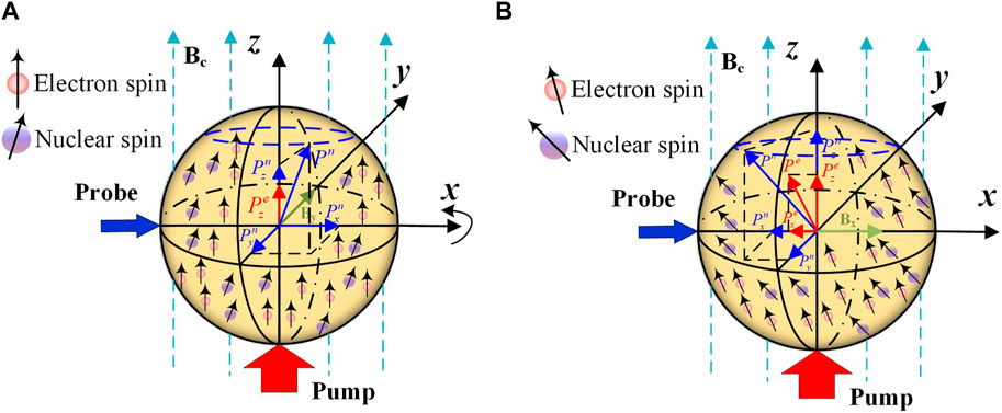
FIGURE 1. (A) Steady-state response of By. (B) Steady-state response of Bx.
The amplitude frequency response of Bx is composed of one proportional link, two second-order oscillation links, and two first-order differential links, and the following equation can be used to define the conversion relationship between Bx and
The two zeros are
The response of Bx with respect to the AC magnetic field signal of frequency ω is expressed as
where
In this study, the SERFC pump laser direction is strictly aligned with the z-axis main magnetic field direction, the detection laser direction is consistent with the x-axis magnetic field compensation direction and is orthogonal to the pump laser direction, and the inertial sensitive axis is the y-axis. In Liu et al. (2022c); Fan et al. [16], the influence of the Bx magnetic field error on the system is analyzed using the magnetic field equivalent velocity sensitivity AMFVS. Based on the previous research, we carried out a more complete derivation and concluded that the expression of the low-frequency bias magnetic field sensitivity (LFBMS) (the low-frequency band studied in SERFC is the spectrum below 10−3 Hz) AMFVS can be expressed as
where ωe = γeBe/Q and ωn = γnBn. The representative measurement parameters in the experiment are shown in Table 2. Since
Obviously,
where
where R is the radius of the vapor cell; DNe−Ne is the diffusion constant of 21Ne in the atomic cell;
On the one hand, the pump light power density affects the magnetic field gradient. From Eq. 27, it is shown that for the decay of the pump rate with the propagation distance z, the D1 line pump light of K atoms propagates in the vapor cell. The strong absorption of pump light by dense alkali-metal atoms in the atomic vapor cell leads to a significant electron spin polarization gradient.
where Rrel is the relaxation rate of the electron spin of the K atom except for the pumping rate; Rp(0) is the initial pump rate when the pump light is incident into the vapor cell; ρ is the distance from the center of the spot; r is the radius of the spot; W is the Lambert-W function; nK is the K-atomic density; and σL(v) is the absorption cross-sectional area of the K-atomic absorption pump light.
The expression for the decay of the alkali-metal polarizability with propagation distance z is
where
where k0 is the Fermi-contact-shift enhancement factor; μ0 is the permeability of vacuum; μB is the Bohr magneton; and ne and nn are the densities of alkali-metal atoms and noble gas, respectively. The distribution simulation of electron and nucleon polarizability under different pump light power densities is shown in Figure 2. Increasing the pump light power density can produce a uniform and saturated spin polarization, but too high pump light power density will reduce the sensitivity of SERFC, so the pump light power density value needs to be set at the corresponding specific polarization rate value [31].
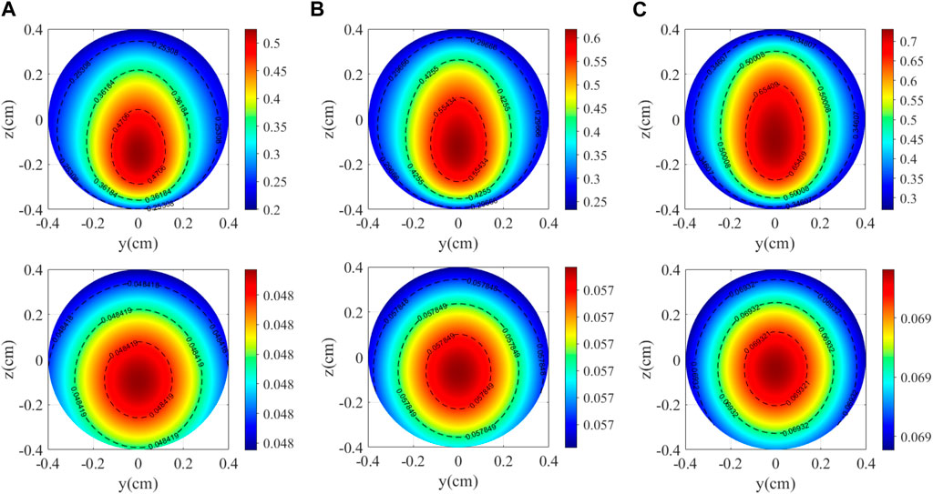
FIGURE 2. Electron and nucleon polarizability distributions at different pump power densities. (A) 84.92 mW/cm2; (B) 127.39 mW/cm2; and (C) 205.34 mW/cm2.
On the other hand, the temperature also affects the magnetic field gradient. The empirical formula of alkali-metal atom density n and temperature of alkali-metal is [32]
where nA and nB are constants related to the type of alkali-metal atom and T is the temperature of the steam cell expressed on the thermodynamic temperature scale. The expression of
where
where σsd is the collision cross-sectional area;
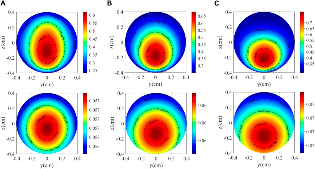
FIGURE 3. Electron and nucleon polarizability distributions at different temperatures. (A) 170°C; (B) 190°C; and (C) 210°C.
The schematic diagram of the SERFC based on K–Rb–21Ne is shown in Figure 4. A spherical vapor cell with a diameter R of 8 mm made of GE180 aluminosilicate glass was placed in a boron nitride ceramic oven. The vapor cell contained 2 amagats of 21Ne (70% isotope-enriched) gas, a natural abundance K and Rb alkali-metal mixture with a density ratio of 1: 94, and 50 torrs of N2. Three layers of μ-metal magnetic shielding cylinder with high permeability are used to shield the external magnetic field, and the innermost layer is MnZn ferrite magnetic shielding cylinder to suppress low-frequency magnetic errors [8]. The pump light is generated by a distributed Bragg reflector (DBR) laser with a center frequency of 770.108 nm (K D1 resonant line), a quarter wave plate in the pump path converts a linearly polarized state to a circularly polarized state, and a pair of planoconvex lenses is used to expand the beam of pump light. The probe beam is generated by a distributed feedback (DFB) laser with a center frequency of 795.311 nm (approximately 0.3 nm to the blue side of the Rb D1 resonance line), and the Glan–Taylor polarizer (GT-5, Thorlabs) can purify the laser to a better linearly polarized laser. The power stability control system of the pump laser and laser consists of a polarizing beam splitter (PBS), liquid crystal variable retarder (LCVR), Glan–Taylor polarizer, half-wave plate, photodetector (PD), and electronic controller.
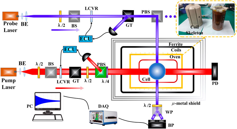
FIGURE 4. Schematic of the K–Rb–21Ne comagnetometer. BE, beam expander; P, linear polarizer; LCVR, liquid crystal variable retarder; GT, Glan–Taylor polarizer; PD, photodiode; PBS, polarizing beam splitter; ECU, electronic control unit; WP, Wollaston prism; BP, balanced photodiode; λ/2, half-wave plate; λ/4, quarter-wave plate.
The three-axis magnetic compensation coils and gradient magnetic coils are used to compensate the residual magnetic field and generate the magnetic field gradient, respectively. According to the magnetic flux continuity principle ∇ ⋅ B = 0, it shows that the magnetic field is a passive field, the magnetic line of force is always a closed curve, and the divergence calculation formula is
so the
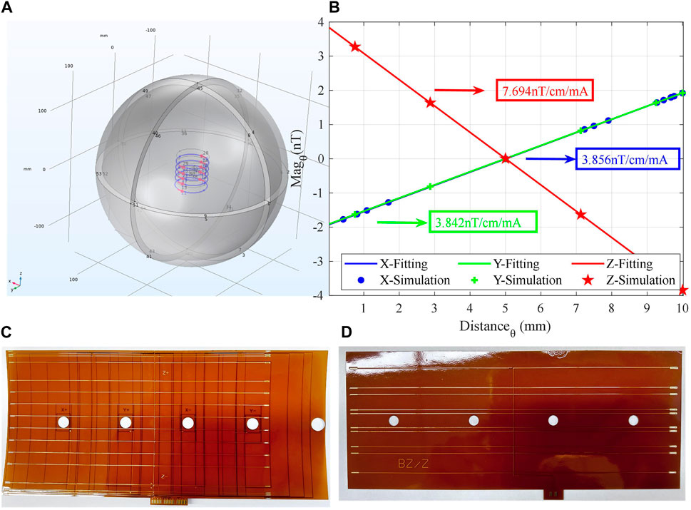
FIGURE 5. (A) Overall model of finite element simulation. (B) Triaxial magnetic field coil constant. (C) Bx, By, and Bz three-in-one uniform magnetic field coil. (D) dBz/dz magnetic field gradient coil.
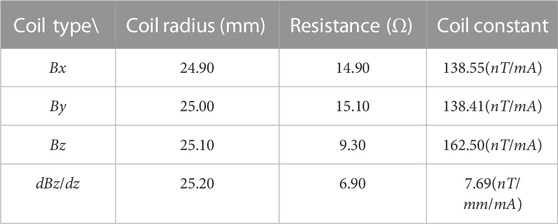
TABLE 1. Design parameters of the magnetic field coil.
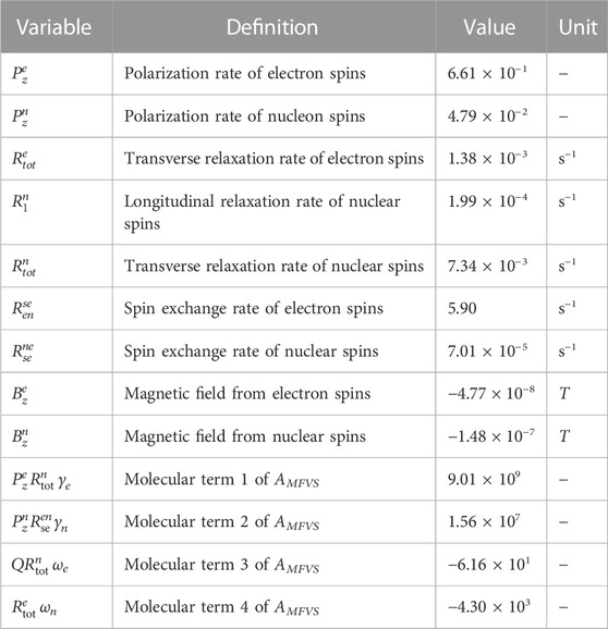
TABLE 2. Summary of the measured parameters.
In this experiment, the spin coupling between electron spin and nuclear spin is decoupled by applying a magnetic field of approximately 1,500 nT, but it does not affect the measurement and fitting of free induction decay (FID) signals [34]. As shown in Figure 6, the relaxation times are obtained by measuring the output of the system at different times and fitting the relationship between the pump time and the precession signal.After measuring T1 and T2 at different magnetic field gradients by the aforementioned method, Eqs 24–25 are verified by fitting the relationship between the relaxation rate of 21Ne and the magnetic field gradient. According to Eqs 26–27, it can be seen that
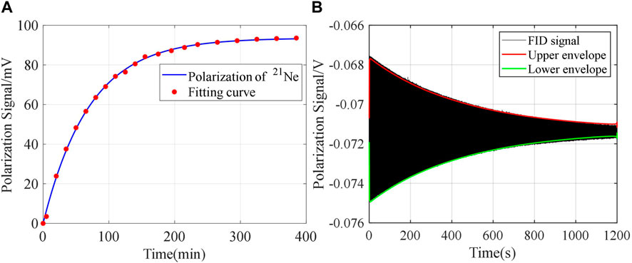
FIGURE 6. (A) Longitudinal relaxation time of nucleon spin. (B) Transverse relaxation time of nucleon spin.
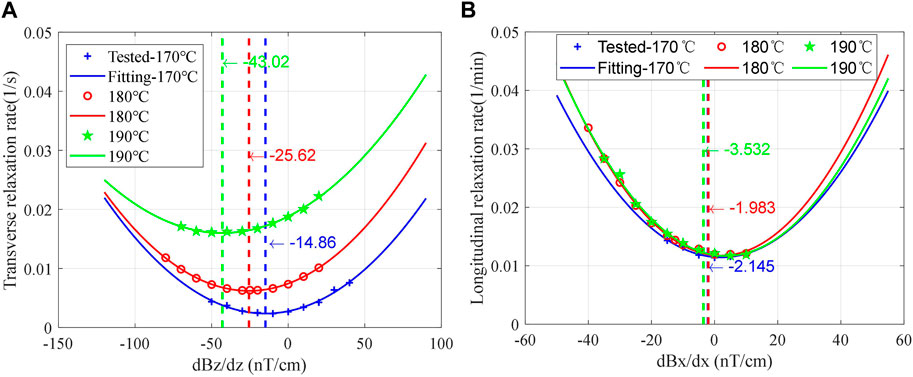
FIGURE 7. Measured at different temperatures: (A) relationship between
The frequency response of the K–Rb–21Ne comagnetometer was obtained by applying 0.5542 nTpp sine waves with a frequency range of 0.01–600 Hz along the x-axis, and the results were fitted with Eq. 21. It can be seen from Figure 8A that both the electronic and nuclear resonance peaks shift to the right with the increase in the vapor cell temperature, indicating that the electron spin polarizability and the nuclear spin polarizability are proportional to the vapor cell temperature. However, according to Eqs 31–33, the LFBMS can be suppressed in two ways: one is by reducing the temperature of the vapor cell to reduce the atomic density nK (in order to improve the polarization of 21Ne and reduce the polarization magnetic field gradient, a hybrid pumping technique is adopted. The density ratio of K and Rb atoms determines the uniformity of polarization, so it is necessary to choose an appropriate atomic density ratio to make SERFC work in the optimal state), and finally
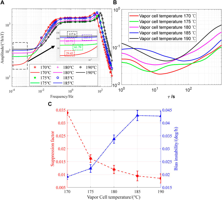
FIGURE 8. (A) Amplitude–frequency response Bx at different cell temperatures. (B) Corresponding Allan deviation at different cell temperatures. (C) Suppression factor and bias instability.
According to Eqs 28–30, increasing the pump light power density can produce a uniform and saturated spin polarization magnetic field gradient. It can be seen from Figure 9A that LFBMS is suppressed with the increase in pump light power density, and the experimental results show that the LFBMS can be suppressed by increasing the pump light power density to improve

FIGURE 9. (A) Amplitude–frequency response Bx at different pump laser power densities. (B) Corresponding Allan deviation at different pump laser power densities. (C) Suppression factor and bias instability.
In addition, the magnetic field gradient is applied to reduce LFBMS by changing the influence of
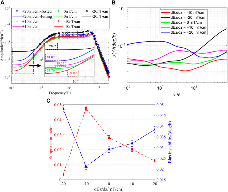
FIGURE 10. (A) Amplitude–frequency response Bx at different magnetic field gradients. (B) Corresponding Allan deviation at different magnetic field gradients. (C) Suppression factor and bias instability.
The K–Rb–21Ne comagnetometer sensitivity to Bx in our research conclusions is comparable to the magnetic field suppression factor of the K–3He comagnetometer reported by [5]. Ref. [14] believes that increasing the electronic magnetic field can suppress the magnetic noise and reduce the magnetic field suppression factor, which is similar to the conclusion of increasing the pump light power density in this study. In Ref. [23], the magnetic field gradient leads to atomic decoherence of the K–Rb–21Ne comagnetometer, which is complementary to the conclusion in this study that low-frequency magnetic field errors are suppressed by active magnetic field gradient compensation.
In conclusion, this paper analyzes the influence of magnetic field gradients on the steady-state response and frequency response of the K–Rb–21Ne comagnetometer. The bias magnetic field sensitivity model of SERFC is modified, and the influence of magnetic field gradients on low-frequency magnetic errors is considered. We experimentally verify that the magnetic field gradient of the K–Rb–21Ne comagnetometer can be measured in situ through the relationship between the relaxation rate and magnetic field gradient. In addition, the LFBMS can be suppressed by optimizing the vapor cell temperature and the pump light power density and using the magnetic field gradient coil to actively compensate for the magnetic field gradient, and it is verified that the magnetic error suppression method proposed in this paper can reduce the LFBMS of SERFC. After the vapor cell temperature is optimized from 170°C to 190°C, the suppression factor and bias instability are optimized by 72.19% and 55.41%, respectively. After the pump power density is optimized from 85 mW/cm2 to 149 mW/cm2, the suppression factor and bias instability are optimized by 20.24% and 20.84%, respectively. After the magnetic field gradient is compensated from −10 nT/cm to 0 nT/cm, the suppression factor and bias instability are optimized by 69.86% and 27.63%, respectively. This work provides an experimental and theoretical basis for measuring the magnetic field gradient of the K–Rb–21Ne comagnetometer and suppressing the low-frequency magnetic field error.
The raw data supporting the conclusion of this article will be made available by the authors, without undue reservation.
Methodology: ZWu, FL, ZWa, WQ, and WF; formal analysis: ZWu and FL; investigation: ZWu and HP; data curation: ZWu and HP; validation: ZWu and HP; writing—original draft preparation: ZWu. All authors contributed to the article and approved the submitted version.
This work was supported in part by the Key Area Research and Development Program of Guangdong Province (Grant No. 2021B0101410005), in part by the National Natural Science Foundation of China (Grant Nos 61673041 and 62103026), and by the China Postdoctoral Science Foundation (Grant No. 2022M720362).
This is a short text to acknowledge the contributions of specific colleagues, institutions, or agencies that aided the efforts of the authors.
The authors declare that the research was conducted in the absence of any commercial or financial relationships that could be construed as a potential conflict of interest.
All claims expressed in this article are solely those of the authors and do not necessarily represent those of their affiliated organizations, or those of the publisher, the editors, and the reviewers. Any product that may be evaluated in this article, or claim that may be made by its manufacturer, is not guaranteed or endorsed by the publisher.
1. Schmidt U, Heil W, Allmendinger F. Comment on new limit on lorentz-invariance- and cpt-violating neutron spin interactions using a free-spin-precession 3He-129Xe comagnetometer reply. Phys Rev Lett (2014) 112.
2. Bear D, Stoner RE, Walsworth RL, Kostelecky VA, Lane CD. Limit on lorentz and cpt violation of the neutron using a two-species noble-gas maser. Phys Rev Lett (2000) 85:5038–41. doi:10.1103/physrevlett.85.5038
3. Vasilakis G, Brown JM, Kornack TW, Romalis MV. Limits on new long range nuclear spin-dependent forces set with a k-3 he comagnetometer. Phys Rev Lett (2009) 103:261801. doi:10.1103/physrevlett.103.261801
4. Hunter L, Gordon J, Peck S, Lin JF. Using the Earth as a polarized electron source to search for long-range spin-spin interactions. Science (2013) 339:928–32. doi:10.1126/science.1227460
5. Kornack TW, Ghosh RK, Romalis MV. Nuclear spin gyroscope based on an atomic co-magnetometer. Phys Rev Lett (2005) 95:230801. doi:10.1103/physrevlett.95.230801
6. Wang Z, Liu S, Wang R, Yuan L, Huang J, Zhai Y, et al. Atomic spin polarization controllability analysis: A novel controllability determination method for spin-exchange relaxation-free co-magnetometers. IEEE/CAA J Automatica Sinica (2022) 9:699–708. doi:10.1109/jas.2021.1004383
7. Zhang C, Yuan H, Tang Z, Quan W, Fang JC. Inertial rotation measurement with atomic spins: From angular momentum conservation to quantum phase theory. Appl Phys Rev (2016) 3:041305. doi:10.1063/1.4972187
8. Dang HB, Maloof AC, Romalis MV. Ultra-high sensitivity magnetic field and magnetization measurements with an atomic magnetometer. Appl Phys Lett (2010) 97:151110. doi:10.1063/1.3491215
9. Lee SK, Romalis MV. Calculation of magnetic field noise from high-permeability magnetic shields and conducting objects with simple geometry. J Appl Phys (2008) 103:084904–190. doi:10.1063/1.2885711
10. Clem J. Johnson noise from normal metal near a superconducting squid gradiometer circuit. IEEE Trans Magnetics (1987) 23:1093–6. doi:10.1109/tmag.1987.1065127
11. Fan W, Quan W, Liu F, Xing L, Liu G. Suppression of the bias error induced by magnetic noise in a spin-exchange relaxation-free gyroscope. IEEE Sensors J (2019) 19:9712–21. doi:10.1109/jsen.2019.2929505
12. Liu Y, Fan W, Fu Y, Pang H, Pei H, Quan W. Suppression of low-frequency magnetic drift based on magnetic field sensitivity in K-Rb-21Ne atomic spin comagnetometer. IEEE Trans Instrumentation Meas (2022) 71:1–8. doi:10.1109/tim.2022.3169541
13. Li R, Quan W, Fan W, Xing L, Fang J. Influence of magnetic fields on the bias stability of atomic gyroscope operated in spin-exchange relaxation-free regime. Sensors Actuators A Phys (2017) 266:130–4. doi:10.1016/j.sna.2017.09.023
14. Shi M. Investigation on magnetic field response of a 87rb-129xe atomic spin comagnetometer. Opt Express (2020) 28:32033–41. doi:10.1364/oe.404809
15. Xing L, Quan W, Fan W, Zhang W, Fu Y, Song T. The method for measuring the non-orthogonal angle of the magnetic field coils of a K-Rb-21Ne co-magnetometer. IEEE Access (2019) 7:63892–9. doi:10.1109/access.2019.2916160
16. Fan W, Quan W, Liu F, Pang H, Xing L, Liu G. Performance of low-noise ferrite shield in a K-Rb-21Ne co-magnetometer. IEEE Sensors J (2020) 20:2543–9. doi:10.1109/jsen.2019.2952121
17. Ma D, Lu J, Fang X, Yang K, Wang K, Zhang N, et al. Parameter modeling analysis of a cylindrical ferrite magnetic shield to reduce magnetic noise. IEEE Trans Ind Elect (2022) 69:991–8. doi:10.1109/tie.2021.3050351
18. Fang X, Wei K, Zhai Y, Zhao T, Chen X, Zhou M, et al. Analysis of effects of magnetic field gradient on atomic spin polarization and relaxation in optically pumped atomic magnetometers. Opt Express (2022) 30:3926–40. doi:10.1364/oe.447041
19. Liu S, Wang R, Yuan L, Wu J, Yuan Q, Zhu J, et al. Transverse light-shift in a spin-exchange relaxation-free co-magnetometer: Measurement, decoupling, and suppression. Opt Express (2022) 30:15310. doi:10.1364/oe.456937
20. Huang J, Wang Z, Fan W, Xing L, Quan W, Duan L, et al. Analysis and suppression of the polarization error for the optical rotation detection system in an atomic comagnetometer. Opt Express (2020) 28:35748. doi:10.1364/oe.406073
21. Cates G, White D, Chien T-R, Schaefer S, Happer W. Spin relaxation in gases due to inhomogeneous static and oscillating magnetic fields. Phys Rev A (1988) 38:5092–106. doi:10.1103/physreva.38.5092
22. McGregor DD. Transverse relaxation of spin-polarized he 3 gas due to a magnetic field gradient. Phys Rev A (1990) 41:2631–5. doi:10.1103/physreva.41.2631
23. Fu Y, Wang Z, Xing L, Fan W, Ruan J, Pang H. Suppression of nonuniform magnetic fields in magnetic shielding system for serf co-magnetometer. IEEE Trans Instrumentation Meas (2022) 71:1–8. doi:10.1109/tim.2022.3178738
24. Pang H, Fan W, Huang J, Liu F, Liu S, Quan W. A highly sensitive in situ magnetic field fluctuation measurement method based on nuclear-spin depolarization in an atomic comagnetometer. IEEE Trans Instrumentation Meas (2022) 71:1–8. doi:10.1109/tim.2022.3166169
25. Liu X, Chen C, Qu T, Yang K, Luo H. Transverse spin relaxation and diffusion-constant measurements of spin-polarized 129xe nuclei in the presence of a magnetic field gradient. Scientific Rep (2016) 6:24122. doi:10.1038/srep24122
26. Zhao J, Ding M, Lu J, Yang K, Ma D, Yao H, et al. Determination of spin polarization in spin-exchange relaxation-free atomic magnetometer using transient response. IEEE Trans Instrumentation Meas (2020) 69:845–52. doi:10.1109/tim.2019.2905308
27. Zhan X, Chen C, Wang Z, Jiang Q, Luo H. Improved compensation and measurement of the magnetic gradients in an atomic vapor cell. AIP Adv (2020) 10:045002. doi:10.1063/1.5127032
28. Huang J, Wang Z, Fan W, Pang H, Zhang K, Yuan L, et al. In-situ evaluation of low-frequency magnetic field fluctuation in an atomic comagnetometer. IEEE Sensors J (2021) 21:22846–52. doi:10.1109/jsen.2021.3106899
29. Vasilakis G. Precision measurements of spin interactions with high density atomic vapors. Princeton, NJ, USA: Princeton Univ. (2011). Ph.D. thesis.
30. Wei K, Zhao T, Fang X, Li H, Quan W, Han B, et al. Simultaneous determination of the spin polarizations of noble-gas and alkali-metal atoms based on the dynamics of the spin ensembles. Phys Rev Appl (2020) 13:044027. doi:10.1103/physrevapplied.13.044027
31. Liwei J, Wei Q, Yixiang L, Liu J, Duan L, Fang J. Effects of pump laser power density on the hybrid optically pumped comagnetometer for rotation sensing. Opt express (2019) 27:27420–30. doi:10.1364/OE.27.027420
32. Alcock CB, Itkin VP, Horrigan MK. Vapour pressure equations for the metallic elements: 298–2500K. Can Metallurgical Q (1984) 23:309–13. doi:10.1179/cmq.1984.23.3.309
33. Liu F, Duan L, Fan W, Pang H, Liu S, Quan W. Suppression of the bias error induced by vapor cell temperature in a spin-exchange relaxation-free gyroscope. IEEE Sensors J (2022) 22:1990–7. doi:10.1109/jsen.2021.3138831
Keywords: spin-exchange relaxation-free, comagnetometer, magnetic field gradient, bias magnetic field sensitivity, low-frequency magnetic error
Citation: Wu Z, Liu F, Wang Z, Fan W, Pang H and Quan W (2023) Comprehensive analysis on the magnetic field error of a K–Rb–21Ne comagnetometer with low-frequency bias magnetic field sensitivity. Front. Phys. 11:1201365. doi: 10.3389/fphy.2023.1201365
Received: 06 April 2023; Accepted: 18 May 2023;
Published: 02 June 2023.
Edited by:
Chong Zu, Washington University in St. Louis, United StatesReviewed by:
C. S. Unnikrishnan, Sun Yat-sen University, ChinaCopyright © 2023 Wu, Liu, Wang, Fan, Pang and Quan. This is an open-access article distributed under the terms of the Creative Commons Attribution License (CC BY). The use, distribution or reproduction in other forums is permitted, provided the original author(s) and the copyright owner(s) are credited and that the original publication in this journal is cited, in accordance with accepted academic practice. No use, distribution or reproduction is permitted which does not comply with these terms.
*Correspondence: Feng Liu, bGl1ZmVuZzE5OTFAYnVhYS5lZHUuY24=; Zhuo Wang, emh1b3dhbmdAYnVhYS5lZHUuY24=
Disclaimer: All claims expressed in this article are solely those of the authors and do not necessarily represent those of their affiliated organizations, or those of the publisher, the editors and the reviewers. Any product that may be evaluated in this article or claim that may be made by its manufacturer is not guaranteed or endorsed by the publisher.
Research integrity at Frontiers
Learn more about the work of our research integrity team to safeguard the quality of each article we publish.