- 1College of Physics, Taiyuan University of Technology, Taiyuan, Shanxi, China
- 2Key Laboratory of Advanced Transducers and Intelligent Control System, Ministry of Education, Taiyuan University of Technology, Taiyuan, Shanxi, China
- 3Shanxi Transportation Technology Research & Development Co., Ltd., Taiyuan, Shanxi, China
- 4Shanxi-Zheda Institute of Advanced Materials and Chemical Engineering, Taiyuan, Shanxi, China
Chaotic laser has attracted a large amount of attention due to its broad spectrum, noise-like characteristics, and photonic integrated chaotic semiconductor lasers have further expanded the application field of chaotic laser for their small size and stable properties. Therefore, a monolithically integrated laser with a distributed Bragg reflector (DBR) is designed. This proposed chaotic laser consists of a distributed feedback (DFB) laser section, a phase section, and a DBR section. DBR grating can provide wavelength detuning to generate mode beating, which enhances chaotic bandwidth and distributed feedback to suppress time delay signature (TDS). The transmission line laser model (TLLM) of chaotic laser is constructed and chaotic characteristics of the integrated chip are investigated. A chaotic signal with a bandwidth of 12.34 GHz and TDS less than 0.065 is obtained. In addition, a map of dynamic states in the parameter space of phase section current and DBR section current is shown, and a wide range of chaotic regions are obtained. The results show that the broadband chaotic laser with a low TDS can be obtained by controlling the parameters reasonably, which is beneficial to realize the application of chaotic laser.
1 Introduction
Chaotic laser is widely used in secure communication [1], high-speed random number generation [2–4], distributed fiber sensing [5–7], chaotic lidar [8], physical key distribution [9], and other fields [10] due to its broad spectrum and noise-like properties. The common chaotic laser sources consist of discrete devices, which are large, unstable, and not suitable for engineering practice. Therefore, the integration of chaotic laser source is vital for its further applications. At present, researchers have proposed a variety of integrated chaotic semiconductor laser structures. For example, Argyris et al. developed a photonic integrated chaotic semiconductor laser chip consisting of a distributed feedback (DFB) laser source section, a gain/absorption section, a phase section, and a passive optical waveguide section with the high-reflection film at the end, which provides optical feedback [11]. This laser chip generates chaotic laser with a time delay signature of approximately 0.5 and a bandwidth of approximately 20 GHz [12]. Harayama et al. proposed a monolithically integrated chaotic laser chip, including a DFB laser, two semiconductor optical amplifiers (SOAs), a photo-detector (PD), and a straight passive waveguide, which can generate chaotic laser with a bandwidth of about 10 GHz [13, 14]. The external cavity of this chip is the part of DFB laser to the right reflection facet. The aforementioned photonic integrated chaotic semiconductor lasers adopt the end-feedback structure with simple structure, but the external cavity length is fixed. This optical feedback structure results in the chaotic laser with notable TDS and a narrow bandwidth [15, 16].
To enhance the chaotic bandwidth, researchers have proposed some novel structures of photonic integrated chaotic semiconductor lasers. Sunada et al. developed a monolithically integrated chaotic laser, including a DFB laser, two SOAs, a PD, and a ring passive waveguide [17]. This ring waveguide structure can obtain larger external cavity length for a certain chip size to achieve stronger optical feedback. This chip can generate chaotic signal with almost vanished auto-correlation, and the chaotic bandwidth is 10 GHz. Tronciu et al. developed a monolithically integrated laser chip, which consists of a DFB laser section, two phase sections, an air gap, and two passive optical waveguides [18, 19]. The chaotic bandwidth is 7 GHz. The chip achieves photonic integration of multi-feedback chaotic semiconductor laser and can suppress the TDS in principle. Our previous work proposed a wavelength-tunable chaotic semiconductor laser, which is composed of a gain section, a distributed Bragg reflector (DBR) section, an SOA section, and a phase section [20]. The reflective facet of the phase section provides optical feedback for the gain section, and the mode beating of resonant cavity frequencies leads to the chaotic laser with a 4.9 GHz bandwidth generated by this laser chip.
In order to suppress the TDS of chaotic laser, our previous work proposed a monolithically integrated chaotic semiconductor laser subject to random feedback and mutual injection, which contains two DFB lasers, two SOAs, and a passive optical waveguide with random grating [21]. Mutual injection of two DFB lasers makes the spectrum flatter and wider. The random grating in passive waveguide provides random optical feedback to suppress the TDS. This laser structure can generate chaotic signals with a TDS of 0.06 and a bandwidth of 13.12 GHz in simulation.
The aforementioned monolithically integrated chaotic lasers are multi-section structures, and the fabrication process is difficult and complex. In this article, we propose a monolithically integrated laser with a DBR. The laser consists of a DFB laser section, a phase section, and a DBR section, which is a three-section chip. The integrated chip with DBR which provides filter feedback can generate broadband chaotic laser with a bandwidth of 12.34 GHz and the TDS less than 0.065.
2 Laser structure and simulation model
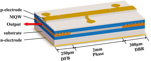
The monolithically integrated chaotic laser consists of a DFB laser section, a phase section, and a DBR section as shown in Figure 1. The DFB section is a multi-quantum well (MQW) structure with an etched grating with a λ/4 phase shift in the center. The DBR section is etched with a homogeneous grating to provide filter feedback for DFB laser. The phase section is a passive waveguide structure to adjust the laser cavity length and the phase of feedback light. The light emitted by the DFB laser is transmitted to the DBR section through the phase section and then fed back to the DFB laser by filter feedback, which disturbs the DFB laser to generate various dynamic states.
The DBR, phase, and DFB sections are equipped with electrodes to add different injection currents, noted as IDBR, IPhase, and IDFB, respectively.
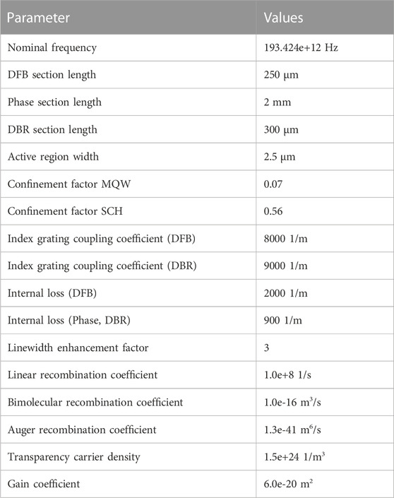
The output characteristics of the integrated chaotic semiconductor laser can be simulated by a transmission line laser model (TLLM). We use VPItransmissionMaker software to build the TLLM of the chaotic laser. The basic principle of the TLLM is to divide the cavity of a laser into small sections and optically couple each section together for calculation [22]. The gain saturation effect, the free-carrier absorption effect, and the free-carrier dispersion effect are taken into account. The parameters used in the simulation are shown in Table 1. These parameters are set by referring to [23] and [24], and the facet reflectivity of the laser is set to 0.
3 Simulation results and analysis
3.1 Map of dynamic states
In order to fully investigate the dynamic states of the chaotic laser, Figure 2A shows the reflection spectra of DBR grating when IDBR changes from 0 to 30.0 mA. It can be seen that the Bragg wavelength of grating moves to the shortwave direction as IDBR increases. It is attributed to the change of the effective refractive index of grating material, when the injected current of the DBR section is changed [25]. The reflectivity of DBR grating at 1550.0 nm is measured as shown in Figure 2B. When IDFB is 50.0 mA, IDBR and IPhase vary from 0 to 35.0 mA and 0 to 20.0 mA, respectively; the laser undergoes various transitions from a steady state to different oscillations. The map of various dynamic states in the parameter space of IDBR and IPhase based on the simulation results is presented in Figure 2C. The central wavelength of the DFB laser is 1,550.0 nm when IDFB is 50.0 mA. The blue, green, yellow, orange, and red areas indicate steady state (S), single-period (P1) oscillation, doubling-period (P2) oscillation, multi-period (PM) oscillation, and chaos (C), respectively. It can be seen that this chaotic laser can generate chaos in a wide range of parameter space.
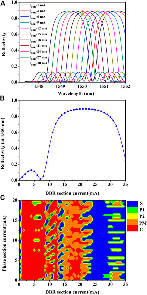
FIGURE 2. (A) Reflection spectra of the DBR grating under different IDBR. (B) Reflectivity of the DBR grating at 1,550.0 nm as functions of IDBR. (C) Map of dynamic states in the parameter space of IDBR and IPhase for IDFB = 50.0 mA. Blue, green, yellow, orange, and red areas correspond to steady state (S), single-period (P1) oscillation, doubling period (P2) oscillation, multi-period (PM) oscillation, and chaos (C), respectively.
The variation of IPhase affects the phase of feedback light and then affects output states of the laser. As shown in Figure 2C, when IDBR = 9.5 mA, the laser can evolve into chaos with the route of S-P1-P2-C as IPhase increases.
In addition, the variation of IDBR has a large impact on output states of the laser. When IDBR = 0 mA, as shown in Figures 2A,B, the reflectivity of the DBR grating to DFB laser is 0, the laser is not subject to feedback, and the output state is a steady state. When IDBR is between 1.0 mA and 8.0 mA, the wavelength of the DFB laser is located in the sidelobe of the DBR reflection spectrum. There are more mode components in the laser, and the output states of the laser are mainly chaos. When IDBR is between 8.0 mA and 15.0 mA, the filter-induced non-linearity is largest where the edge slope of the filter reflection spectrum is maximal [26]. As IDBR increases, the filter feedback strength gradually enhances, and the laser can output steady state, periodic states, and chaos. When IDBR is between 15.0 mA and 23.0 mA, the wavelength of the DFB laser is aligned with the peak of the DBR reflection spectrum, and the filter feedback strength is basically unchanged. The output states of the laser mainly include multi-periodic states and chaotic states. When IDBR is further increased, the wavelength of the DFB laser gradually moves away from the central wavelength of the DBR grating. The change of detuning sometimes leads to discontinuities in the output state [26], and the output of the laser is mostly steady state. When IDBR increases to 28.0 mA, the wavelength of the DFB laser is gradually aligned with the maximum slope of the edge of the DBR reflection spectrum, the output states present periodic states. As IDBR increases, the filter feedback strength gradually weakens, and the output states are mainly steady state. By controlling IDBR, the laser can output rich dynamic states and more complex chaotic signals.
3.2 Broadband chaos with suppressed TDS
It is further found that the laser can output broadband chaotic laser with suppressed TDS under suitable bias currents. Figure 3A–Figure 3D show the simulation results of the optical spectrum, power spectrum, time domain series, and auto-correlation function of the output signal at IDFB = 50.0 mA, IPhase = 16.0 mA, and IDBR = 8.0 mA. At this time, IDFB is 3.4 times its threshold current, and the central Bragg wavelength of DBR grating is 1,551.0 nm. In Figure 3A, the optical spectrum broadens more evidently and contains more optical frequency components. The power spectrum characteristics of the chaotic signal are described by the 80% standard bandwidth, which is defined as the span from the DC component to the frequency where 80% of energy is contained in the whole power spectrum [27]. As shown in Figure 3B, the bandwidth of the chaotic signal is 12.34 GHz, and the energy is uniformly distributed over a wide frequency range. As shown in Figure 3C, the time domain series of the output signal oscillates violently and is disordered, showing quasi-random fluctuations. The peak position of auto-correlation function is used to identify TDS [28, 29]. As shown in Figure 3D, the TDS of the chaotic laser is lower than 0.065.
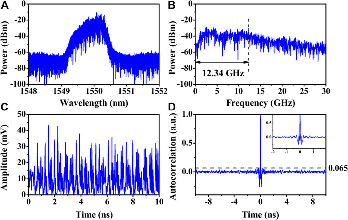
FIGURE 3. Typical chaotic laser state of (A) optical spectrum; (B) power spectrum; (C) time domain series; and (D) auto-correlation function at IDFB = 50.0 mA, IPhase = 16.0 mA, and IDBR = 8.0 mA.
In order to illustrate the TDS suppression of the proposed laser with DBR, an equivalent end-facet feedback structure is simulated, which is a two-section structure without DBR. The equivalent end-facet feedback structure consists of a DFB laser and a passive waveguide with the high-reflection film at the end, and its cavity length is fixed. The length of the passive waveguide is obtained by commuting the equivalent external cavity time delay, and its right end-facet reflectivity is set to 1.
The comparison of the TDS suppression between the proposed laser with DBR and the equivalent end-facet feedback structure is shown in Figure 4.
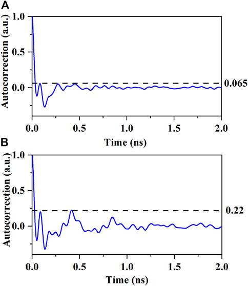
FIGURE 4. Comparison of TDS suppression between the proposed laser with the DBR and the equivalent end-face feedback structure (A) Auto-correlation function of the proposed laser with the DBR. (B) Auto-correlation function of the equivalent end-face feedback structure.
Figure 4A is the auto-correlation function of the proposed laser with DBR whose TDS is less than 0.065. Figure 4B shows the auto-correlation function of the equivalent end-facet feedback structure; the TDS is approximately 0.22. It can be seen that the TDS can be reduced from 0.22 to 0.065. The proposed laser can greatly suppress the TDS due to the introduction of DBR grating compared to the equivalent end-facet feedback structure with a fixed cavity length. More than 1,000 small gratings form multi-cavity coupling feedback, which makes the TDS lower than the auto-correlation sidelobe noise level.
3.3 The dependence of bandwidth on DBR current and coupling coefficient
To further explore the chaotic bandwidth characteristics, the effects of IDBR and DBR grating coupling coefficient κ on the chaotic are simulated.
Figure 5 shows the effects of IDBR on chaotic characteristics, when the DBR grating coupling coefficient κ is 9,000/m. The optical spectra of chaos generated by different IDBRs are shown in Figures 5A1–5E1. The orange curve marks the reflection spectrum of DBR grating, the gray curve indicates the free running output of the DFB laser, and the blue curve represents the generated chaos. The corresponding power spectra are shown in Figures 5A2–5E2.
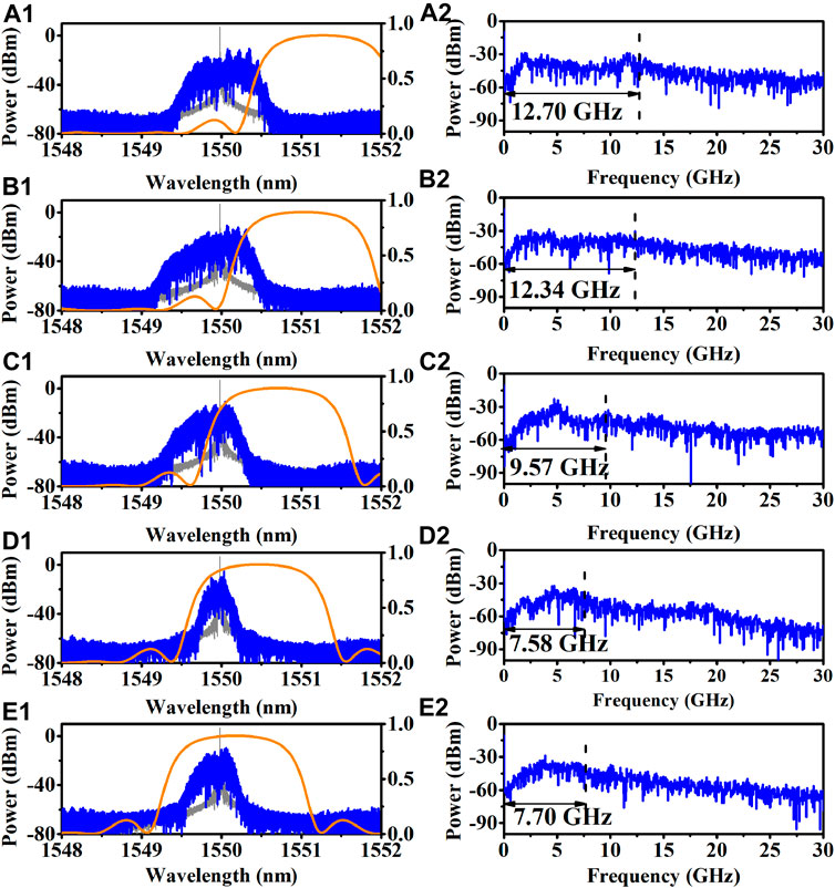
FIGURE 5. Effects of IDBR on laser output characteristics. IDFB = 50.0 mA, IPhase = 16.0 mA; (A) IDBR = 5.0 mA; (B) IDBR = 8.0 mA; (C) IDBR = 12.0 mA; (D) IDBR = 15.0 mA; and (E) IDBR = 19.0 mA.
When IDBR = 5.0 mA, the wavelength of the DFB laser is located in the sidelobe of the DBR reflection spectrum. As shown in Figure 5A1, the optical spectrum has more frequency components and is significantly broadened. Meanwhile, as shown in Figure 5A2, the chaotic bandwidth is wider due to the large wavelength detuning between the Bragg wavelength of DBR grating and the center wavelength of the DFB laser. With the increase of IDBR, the central wavelength of the DBR grating moves toward the shortwave direction and the sidelobe of the DBR reflection spectrum gradually moves away from the wavelength of the DFB laser. The mode components in the laser gradually decrease, as shown in Figure 5B–Figure 5D, and the optical spectrum linewidth lessens significantly. The wavelength detuning gradually degrades, and the chaotic bandwidth becomes narrow. The central wavelength of the DFB laser is red shifted under the influences of optical feedback. With further increase of IDBR, the wavelength detuning rises. As shown in Figure 5E, the optical frequency components increase, the optical spectrum linewidth enhances, and the power spectrum broadens and is flatter.
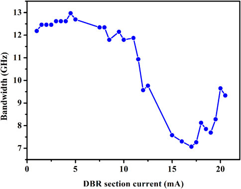
Figure 6 shows the chaotic bandwidth as a function of IDBR. As IDBR increases from 1.0 mA to 5.0 mA, the chaotic bandwidth remains around 12.3 GHz. The wavelength detuning between the Bragg wavelength of the DBR grating and the central wavelength of the DFB laser is large. The mode beating between the optical mode filtered by the reflection spectrum of the DBR grating and the optical mode of the DFB laser results in the wide chaotic bandwidth. With the increase of IDBR, the Bragg wavelength of DBR grating moves to the short-wave direction. The wavelength detuning gradually degrades, the mode beating gradually weakens, and the chaotic bandwidth gradually decreases. Owing to the effects of optical feedback, the central wavelength of the DFB laser is red shifted. The chaotic bandwidth reaches the minimum when IDBR is increased to 17.0 mA. With further increase of IDBR, the wavelength detuning rises, and the chaotic bandwidth shows an increasing trend.
The peak reflectivity and reflection spectrum width of DBR grating are related to the DBR grating coupling coefficient κ. The coupling coefficient κ represents the amount of reflection per unit length. Therefore, when κ is larger, the peak reflectivity is larger, and the reflection spectrum width is wider [22]. Figure 7 shows the effects of the DBR grating coupling coefficient κ on the chaotic bandwidth for IDFB = 50.0 mA, IPhase = 16.0 mA, and IDBR = 8.0 mA. The optical spectra of chaos are shown in Figures 7A1–7D1. The orange curve marks the reflection spectrum of DBR grating, the gray curve indicates the free running output of the DFB laser, and the blue curve represents the generated chaos. The corresponding power spectra are shown in Figures 7A2–7E2.
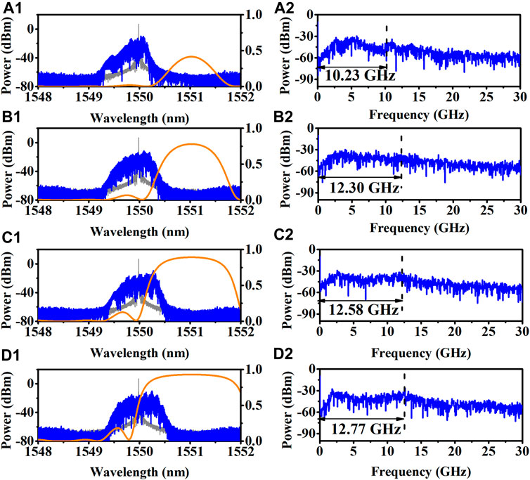
FIGURE 7. Effects of the DBR grating coupling coefficient κ on laser output characteristics. IDFB = 50.0 mA, IPhase = 16.0 mA, IDBR = 8.0 mA; (A) κ = 3,000/m; (B) κ = 6,000/m; (C) κ = 9,000/m; (D) κ = 12000/m.
When the DBR grating coupling coefficient κ is 3,000/m, as shown in Figure 7A, the peak reflectivity and reflection spectrum width are small. The DBR grating provides the weak feedback strength. At this time, the mode components are less, and the chaotic bandwidth is narrow. With the further increase of κ, the peak reflectivity and reflection spectrum width gradually rise. The limiting effect of grating on the mode components is reduced, and more frequency components disturb this laser. The chaotic optical spectrum gradually broadens, the time domain series fluctuation becomes more intense, and the chaotic bandwidth broadens, as shown in Figure 7B–Figure 7D, respectively.
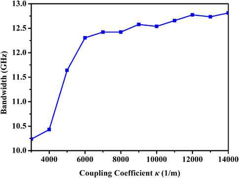
Figure 8 shows the chaotic bandwidth as functions of the DBR grating coupling coefficient κ. As κ increases, the peak reflectivity and reflection spectrum width gradually rise, and the feedback strength provided by DBR grating gradually rises. When κ is between 3,000/m and 6,000/m, the power spectra of chaos broaden fast. When κ > 6000/m, the increasing trend of chaotic bandwidth slows down, mainly because with the increase of κ, the reflection spectrum width is already large. The constraint of the reflection spectrum on optical frequency components has been greatly weakened.
Furthermore, in order to comprehensively investigate the distribution of broadband chaos in different parameter spaces, map of bandwidth, and dynamic states in the parameter space of IDBR and DBR grating coupling coefficients κ is simulated at IDFB = 50.0 mA and IPhase = 16.0 mA, as shown in Figure 9. Different colors indicate the chaotic bandwidth and other fundamental frequencies of oscillations, where S denotes steady state, P1 denotes single-period oscillation, P2 denotes doubling period oscillation, PM denotes multi-period oscillation, and C denotes chaos. It can be seen that with the increase of κ, the region of chaos gradually expands. When κ is 14,000/m, the laser can generate chaos in the range from 1.0 mA to 25.0 mA for IDBR. As κ rises, the chaotic bandwidth gradually enhances, and the dynamic states also increase. The main reason is that when κ is larger, the peak reflectivity of grating is larger, and the width of the reflection spectrum is wider. The DBR grating has less limiting effect on optical frequency components. Also, the broadband chaotic laser is generated at 1.0 mA from 12.0 mA for IDBR, same as Figure 2C, which is mainly influenced by the sidelobe of the DBR reflection spectrum and the large wavelength detuning. When IDBR = 21.0 mA, the wavelength detuning is 0. Further adding the IDBR, the output states are mainly S and PM in the case of positive detuning.
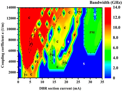
FIGURE 9. Map of bandwidth and dynamic states in the parameter space of IDBR and the DBR grating coupling coefficient κ at IDFB = 50.0 mA and IPhase = 16.0 mA. S, P1, P2, PM, and C correspond to steady state, single-period oscillation, doubling period oscillation, multi-period oscillation, and chaos, respectively.
4 Discussion
DBR grating is widely used in integrated lasers [30], such as wavelength-tunable lasers, which are very suitable for gas-sensing systems [31, 32]. In these applications, the narrow-linewidth tunable laser is needed. In this paper, DBR grating is introduced into the integrated laser to generate broadband chaotic laser with the TDS suppressed. The designed laser chip uses a DBR grating structure, which can control the laser dynamics and characteristics of chaotic laser via the reflection spectrum width, peak reflectivity, and wavelength detuning. Owing to mode beating between the optical mode filtered by the reflection spectrum of DBR grating and the mode of the DFB laser, the low-frequency components are excited, the energy is evenly distributed in a wide frequency range, and the chaotic bandwidth increases. With the increase of IDBR, the Bragg wavelength of the DBR grating moves to the short-wave direction. The wavelength detuning between the Bragg wavelength of the DBR grating and the central wavelength of the DFB laser gradually degrades, and the chaotic bandwidth gradually decreases. Until the wavelength detuning changes from negative detuning to positive detuning, with the further increase of IDBR, the chaotic bandwidth shows an increasing trend. Meanwhile, the reflection spectrum width and peak reflectivity can be controlled by changing the DBR grating coupling coefficient κ. As κ increases, the peak reflectivity and reflection spectrum width gradually enhance. The limiting effect of grating on the optical frequency components is reduced, and the feedback strength provided to the DFB laser is enhanced, which makes the chaotic bandwidth broadened. A number of small gratings in the DBR structure form multi-cavity coupled feedback, which can effectively suppress the TDS of chaotic laser. Therefore, both κ and grating length can control the reflection spectrum shape of DBR grating, as the peak reflectivity and reflection spectrum width. However, changing grating length also affects the cavity length of the laser and optical absorption loss. In contrast, the effect of κ on the grating reflection spectrum is more concise. Also, κ can be controlled by the parameters such as the etching depth of grating in the experiment.
5 Conclusion
In conclusion, a monolithically integrated laser with DBR is established in simulation. The DBR grating provides wavelength detuning to generate mode beating, which enhances chaotic bandwidth and distributed feedback to suppress TDS. When the IDBR is small, the wavelength of the DFB laser is located in the sidelobe of the DBR reflection spectrum, and the wavelength detuning is large. The laser can output chaotic states with wide bandwidth. When the DBR grating coupling coefficient κ is large, the peak reflectivity and reflection spectrum width enhance, and the chaotic bandwidth broadens. The results show that the designed laser chip can generate chaotic signal with the bandwidth of 12.34 GHz and a TDS less than 0.065, which can provide an integrated broadband chaotic signal source for secure communication, high-speed random number generation, distributed fiber sensing, and other fields.
Data availability statement
The original contributions presented in the study are included in the article/supplementary material; further inquiries can be directed to the corresponding authors.
Author contributions
SL: simulation design, data processing, interpretation of data, and manuscript writing. LQ: study support, interpretation of data, and manuscript review. MC: interpretation of data and manuscript review. MZ: study support and manuscript review. All authors have read the manuscript and agreed to the published version of the manuscript.
Funding
This work was supported in part by the National Natural Science Foundation of China (62075151 and 62105234); the Key Research and Development Project of Shanxi Province (202202030201004); the Shanxi “1331 Project” Key Innovative Research Team; Program for Sanjin Scholar; and the Shanxi-Zheda Institute of Advanced Materials and Chemical Engineering.
Conflict of interest
LQ is employed by the company Shanxi Transportation Technology Research & Development Co Ltd.
The remaining authors declare that the research was conducted in the absence of any commercial or financial relationships that could be construed as a potential conflict of interest.
Publisher’s note
All claims expressed in this article are solely those of the authors and do not necessarily represent those of their affiliated organizations, or those of the publisher, the editors, and the reviewers. Any product that may be evaluated in this article, or claim that may be made by its manufacturer, is not guaranteed or endorsed by the publisher.
References
1. Argyris A, Syvridis D, Larger L, Annovazzi-Lodi V, Colet P, Fischer I, et al. Chaos-based communications at high bit rates using commercial fibre-optic links. Nature (2005) 438(17):343–6. doi:10.1038/nature04275
2. Uchida A, Amano K, Inoue M, Hirano K, Naito S, Someya H, et al. Fast physical random bit generation with chaotic semiconductor lasers. Nat Photon (2008) 2(12):728–32. doi:10.1038/nphoton.2008.227
3. Kanter I, Aviad Y, Reidler I, Cohen E, Rosenbluh M. An optical ultrafast random bit generator. Nat Photon (2010) 4(1):58–61. doi:10.1038/nphoton.2009.235
4. Li NQ, Kim B, Chizhevsky VN, Locquet A, Bloch M, Citrin DS, et al. Two approaches for ultrafast random bit generation based on the chaotic dynamics of a semiconductor laser. Opt Exp (2014) 22(6):6634–6646. doi:10.1364/OE.22.006634
5. Li J, Zhang MJ. Physics and applications of Raman distributed optical fiber sensing. Light-sci Appl (2022) 11(1):128. doi:10.1038/s41377-022-00811-x
6. Zhou XX, Li J, Xu Y, Yin ZT, Wang CY, Yu FH, et al. Chaos Raman optical time-domain reflectometry for millimeter-level spatial resolution temperature sensing. J Lightw.Technol (2021) 39(23):1–7538. doi:10.1109/JLT.2021.3116203
7. Wang YH, Zhang MJ, Zhang JZ, Qiao LJ, Wang T, Zhang Q, et al. Millimeter-level-spatial-resolution Brillouin optical correlation-domain analysis based on broadband chaotic laser. J Lightw.Technol (2019) 37(15):3706–12. doi:10.1109/JLT.2019.2916801
8. Lin FY, Liu JM. Chaotic lidar. IEEE J Sel Top Quan Electron. (2004) 10(5):991–7. doi:10.1109/JSTQE.2004.835296
9. Gao H, Wang AB, Wang LS, Jia ZW, Guo YY, Gao ZS, et al. 0.75 Gbit/s high-speed classical key distribution with mode-shift keying chaos synchronization of Fabry–Perot lasers. Light-sci Appl (2021) 10(1):172. doi:10.1038/s41377-021-00610-w
10. Sciamanna M, Shore KA. Physics and applications of laser diode chaos. Nat Photon (2015) 93(3):151–62. doi:10.1038/nphoton.2014.326
11. Syvridis D, Argyris A, Bogris A, Hamacher M, Giles I. Integrated devices for optical chaos generation and communication applications. IEEE J Quan Electron (2009) 45(11):1421–8. doi:10.1109/JQE.2009.2027336
12. Chlouverakis KE, Argyris A, Bogris A, Syvridis D. Hurst exponents and cyclic scenarios in a photonic integrated circuit. Phys Rev E (2008) 78(6):066215. doi:10.1103/PhysRevE.78.066215
13. Sunada S, Harayama T, Arai K, Muramatsua J, Yoshimuraa K, Tsuzukib K, et al. Theory and experiments of fast non-deterministic random bit generation using on-chip chaos lasers. Proced IUTAM (2012) 5:190–4. doi:10.1016/j.piutam.2012.06.025
14. Harayama T, Sunada S, Yoshimura K, Davis P, Tsuzuki K, Uchida A. Fast nondeterministic random-bit generation using on-chip chaos lasers. Phys Rev A (2011) 83(3):031803. doi:10.1103/PhysRevA.83.031803
15. Rontani D, Locquet A, Sciamanna M, Citrin DS, Ortin S. Time-delay identification in a chaotic semiconductor laser with optical feedback: A dynamical point of view. IEEE J Quan Electron. (2009) 45(7):879–1891. doi:10.1109/JQE.2009.2013116
16. Wang AB, Wang YC, He HC. Enhancing the bandwidth of the optical chaotic signal generated by a semiconductor laser with optical feedback. IEEE Photon Technol Lett (2008) 20(19):1633–5. doi:10.1109/LPT.2008.2002739
17. Sunada S, Harayama T, Arai K, Yoshimura K, Davis P, Tsuzuki K, et al. Chaos laser chips with delayed optical feedback using a passive ring waveguide. Opt Exp (2011) 19(7):5713–5724. doi:10.1364/OE.19.005713
18. Tronciu VZ, Mirasso C, Colet P, Hamacher M, Benedetti M, Vercesi V, et al. Chaos generation and synchronization using an integrated source with an air gap. IEEE J Quan Electron. (2010) 46(12):1840–6. doi:10.1109/JQE.2010.2049642
19. Tronciu VZ, Mirasso CR, Colet P. Chaos-based communications using semiconductor lasers subject to feedback from an integrated double cavity. J Phys B-at Mol Opt (2008) 41(15):155401. doi:10.1088/0953-4075/41/15/155401
20. Chai MM, Qiao LJ, Li SH, Wei XJ, Xu HC, Zhao J, et al. Wavelength-tunable monolithically integrated chaotic semiconductor laser. J Lightw.Technol (2022) 40(17):5952–7. doi:10.1109/JLT.2022.3184966
21. Chai MM, Qiao LJ, Zhang MJ, Wang AB, Yang Q, Zhang JZ, et al. Simulation of monolithically integrated semiconductor laser subject to random feedback and mutual injection. IEEE J Quan Electron. (2020) 56(5):1–8. doi:10.1109/JQE.2020.3010812
22. Lowery AJ. New dynamic semiconductor laser model based on the transmission-line modelling method. IEEE Proc.-J Optoelectron (1987) 134(5):281–289. doi:10.1049/ip-j.1987.0047
23. Whiteaway JEA, Thompson GHB, Collar AJ, Armistead CJ. The design assessment of lambda/4 phase-shifted DFB laser structures. IEEE J Quan Electron. (1989) 25(6):1261–79. doi:10.1109/3.29257
25. Yu HY, Wang MQ, Zhou DB, Zhou XL, Wang PF, Liang S, et al. A 1.6-mu m widely tunable distributed Bragg reflector laser diode based on InGaAs/InGaAsP quantum-wells material. Opt Commun (2021) 497:127201. doi:10.1016/j.optcom.2021.127201
26. Kane DM, Shore KA. Unlocking dynamical diversity: Optical feedback effects on semiconductor lasers. John Wiley & Sons, Ltd. (2005). 62–70.
27. Lin FY, Liu JM. Nonlinear dynamical characteristics of an optically injected semiconductor laser subject to optoelectronic feedback. Opt Commun (2003) 221(1-3):173–80. doi:10.1016/S0030-4018(03)01466-4
28. Hegger R, Bünner MJ, Kantz H, Giaquinta A. Identifying and modeling delay feedback systems. Phys Rev Lett (1998) 81(3):558–61. doi:10.1103/PhysRevLett.81.558
29. Wu Y, Wang YC, Li P, Wang AB, Zhang MJ. Can fixed time delay signature be concealed in chaotic semiconductor laser with optical feedback? IEEE J Quan Electron. (2012) 48(11):1371–9. doi:10.1109/JQE.2012.2212001
30. Dhoore S, Koninger A, Meyer R, Roelkens G, Morthier G. Electronically tunable distributed feedback (DFB) laseron silicon. Laser Photon Rev (2019) 13(3):1800287. doi:10.1002/lpor.201800287
31. Liu NW, Xu LG, Zhou S, Zhang L, Li JS. Simultaneous detection of multiple atmospheric components using an NIR and MIR laser hybrid gas sensing system. ACS sens (2020) 5(11):3607–16. doi:10.1021/acssensors.0c01910
Keywords: photonic integrated chaotic laser, distributed Bragg reflector, chaos, broad bandwidth, time delay signature suppression
Citation: Li S, Qiao L, Chai M and Zhang M (2023) Monolithically integrated laser with DBR for wideband and low time delay signature chaos generation. Front. Phys. 11:1191597. doi: 10.3389/fphy.2023.1191597
Received: 22 March 2023; Accepted: 11 April 2023;
Published: 02 May 2023.
Edited by:
Jingsong Li, Anhui University, ChinaReviewed by:
Ningwuu Liu, The Chinese University of Hong Kong, ChinaNianqiang Li, Soochow University, China
Siwei Sun, Chinese Academy of Sciences (CAS), China
Copyright © 2023 Li, Qiao, Chai and Zhang. This is an open-access article distributed under the terms of the Creative Commons Attribution License (CC BY). The use, distribution or reproduction in other forums is permitted, provided the original author(s) and the copyright owner(s) are credited and that the original publication in this journal is cited, in accordance with accepted academic practice. No use, distribution or reproduction is permitted which does not comply with these terms.
*Correspondence: Lijun Qiao, cWlhb2xpanVuQHR5dXQuZWR1LmNu; Mingjiang Zhang, emhhbmdtaW5namlhbmdAdHl1dC5lZHUuY24=
 Shuhui Li1
 Lijun Qiao