 Huaibin Qiu1
 Xiaosong Liu
 Kaiqing Wang
 Jianglei Di
- 1Institute of Advanced Photonics Technology, School of Information Engineering, and Guangdong Provincial Key Laboratory of Information Photonics Technology, Guangdong University of Technology, Guangzhou, China
- 2Key Laboratory of Light Field Manipulation and Information Acquisition, Ministry of Industry and Information Technology, and Shaanxi Key Laboratory of Optical Information Technology, School of Physical Science and Technology, Northwestern Polytechnical University, Xi’an, China
Real-time phase measurement is of great value to study the evolution of optical vortex. However, it cannot be recorded in real time due to the limitation of the exposure time of the recording device in the experiment. Therefore, based on the temporal and spatial evolution correlation of the optical phase, a real-time phase measurement method of optical vortex generated by an acoustically induced fiber grating is proposed based on digital holographic reconstruction algorithm. First, a series of holograms are continuously recorded using a low frame rate CCD. Then, the evolution of optical vortex over time is translated into changes in transmission distance. Furthermore, the unrecorded vortex phase distributions are calculated using diffraction theory. By serializing these phase maps over time, the propagation and evolution of spiral phase structure of the vortex beam can be demonstrated in real time.
1 Introduction
Optical vortex, characterized by exotic spatial polarization or phase singularities, has attracted a great deal of research interest in the last decade [1–3]. Owing to the singular properties of spiral phase and polarization distributions, optical vortex is widely used in many research and application fields. For example, tightly focused vortex beams are used in optical tweezers to manipulate particles such as cells and targeted drug [4, 5]. Due to the orbital angular momentum (OAM) of the vortex beam, such particles can be rotated around the axis of the beam. In the stimulated emission depletion (STED) microscopy technique, the tight focusing of the vortex beam can produce a hollow ring focus, which can be used to deplete the fluorophores around a desired area and keep the fluorophores in the desired target area and that enables spatial resolution beyond normal optical diffraction limits [5, 6]. In addition, in the field of optical communication, the introduction of optical vortex can increase the number of optical modes for information transmission, thereby increasing significantly the bandwidth of optical communication. For instance, the twisted radio beams produced by combining vortex phases with radio technology can increase the way information is transmitted and provide new technologies for the development of the radio field [7, 8]. The order of the vortex phase is related to the number of states of the orbital angular momentum, and the vortex beams of different OAMs are orthogonal to each other. The spectral efficiency of high-capacity millimeter-wave communications can be potentially increased with OAM multiplexing [9]. Similarly, in the field of quantum computing research, the use of optical vortices for information encoding and storage can theoretically achieve almost infinite storage capacity, as there is no limit to the topological charge. It also enables faster data processing. Therefore, quantum computing could also benefit from the study of OAM [10, 11].
The acquisition of phase evolution of the vortex beam is of significance to study OAM. We can predict the phase distribution of the regular vortex beam via theoretical calculation. However, the evolution of the irregular vortex phases is difficult to be accurately predicted, such as the interference field of multiple vortex beams. In addition, there are still some differences between the theoretically predicted phase evolution results and the actual phase distribution. Thus, it is particularly necessary to provide real time and accurate measurement means for the vortex phase. To this end, a linear scanning pinhole sampling array based on a liquid crystal spatial light modulation (SLM) was proposed to reconstruct the wave front [12]. However, scanning the whole surface is time-consuming, and the measurement efficiency is too low to realize high-speed and large-area measurement. The solution to the phase image is contradictory with the instantaneity of this method. Dudley provided a method to measure the wave front of propagating light field based on the Stokes parameters via combining SLM, polarization grating, and beam splitter [13]. However, the refresh rate of SLM is far from sufficient compared with the change in the vortex phase. In addition, the measurement requires pixel-level position matching because the two images are projected in the different positions of the detector. Zhang [14] used pixelated micro-polarizer array (PMA) to measure the vortex beam by using the four-step phase-shifting method. The pixel size and position of PMA must completely match with the CCD used, and PMA needs to be changed when using different sizes of CCDs. The practical resolution is only half of CCD’s size because of the use of PMA. Additionally, Lu presented a phase analysis method for a partially coherent vortex beam, where a movable perturbation was introduced at a certain point in an illumination window of finite size. The method cannot achieve wide-field real-time measurement [15].
In this paper, a digital holographic method based on a modified Mach–Zehnder interferometer is developed to measure the optical vortex generated by an acoustically induced fiber grating (AIFG). Digital holography, as a wide-field measurement method to obtain the complex amplitude of light waves in real time [16, 17], has been widely applied in flow-field analysis, beam analysis, near-field imaging, wave front acquisition and processing, bioimaging, computation imaging with deep learning, etc. [18–23]. In digital holography, the complex amplitude distribution of the object beam is recorded in the fringe distribution of the interference pattern and the original object light wave can be obtained by numerically reconstructing the interference pattern. By this way, the phase distribution and evolution of the optical vortex can be obtained. By continuously recording the holograms of the optical vortex using a high-speed camera and numerically reconstructing the phase maps, we can obtain the real-time full-field distribution of the optical vortex and its evolution in the form of a phase map video. Although the CCD frame rate limits the speed of real-time acquisition, digital holographic wave front reconstruction can recover the missing frames from the wave front evolution. This actually realizes the real-time measurement of the vortex phase.
2 Theory
The lowest-order acoustic flexural mode F11 [24], which is antisymmetric with respect to its vibration direction, can propagate along an unjacketed fiber with cylindrical symmetry. The corresponding refractive index distribution in the unjacketed fiber induced by the F11 mode is also antisymmetric and can be described with [25, 26]
where, n0 is the refractive index of the fiber core, c is the optical elastic coefficient of silica, K and u0 are the wavevector and amplitude of the acoustic flexural wave, respectively. (x, y) is the coordinate of the section of the mode field.
The mode coupling coefficient κij between the vector modes i (HEx/y11) and j (TE01, HEeven/odd21, and TM01) of the AIFG can be expressed as [25, 27]
where, ε0 and μ0 are the vacuum permittivity and vacuum permeability, respectively. Ei(x, y) and Ej(x, y) are the transverse electric field distributions of the fundamental vector modes (HEx/y11) and the four high-order vector modes (TE01, HEeven/odd21, TM01), respectively. The coefficient κij can be calculated by Eq. (2) when the polarized angle θ between the acoustic mode F11 and the optical mode HE11 varied. Then result shows, HEy11 can be coupled only to TE01 and HEodd21 when θ = 90°. Whereas θ = 0°, HEx11 can be converted only to HEeven21 and TM01.
To allow the mode conversion from HEx/y11 to HEeven/odd21 while preventing the generation of TE01 and TM01 modes, the phase matching condition LB = Λ should be satisfied, where LB = λ/(nHE 1−nHE 21) is the beat length between HEx/y11 and HEeven/odd21 modes, λ is the resonance wavelength of the AIFG, nHE 11 and nHE 21 are the effective refractive indices of HEx/y11 and HEeven/odd21 modes, and both pairs of HEx/y11 (HEeven/odd21) modes are degenerate, respectively. The dispersion equation of the acoustic flexural wave propagating along the unjacketed fiber can be written as Λ = (πCextR/f)1/2 [28], where the phase velocity in silica Cext is 5760 m/s and R and f are the radius of the fiber and the frequency of the acoustic wave, respectively.
As for the acquisition of the optical vortex phase, considering that the object wave O(x, y) and reference wave R(x, y) interfere with each other on the target plane, the intensity of the interference pattern can be given by
Reconstructing the digital hologram via the convolution method, the complex amplitude distribution of the original light field U(ξ, η) can be obtained by
where FFT and IFFT represent the Fourier and inverse Fourier transform operations, respectively. g(ξ, η, x, y) is the impulse response function of the coherent system. C(x, y) is the simulated planar reference wave.
Assuming that the reconstructed object waves of the background beam and vortex beam are U1(ξ,η) and U2(ξ, η), respectively. According to the double-exposure method for eliminating the background errors [29–31], the unbiased phase distribution ∆φ is given by
where arg( ) is the function to obtain the argument value. Since it is impossible to obtain a phase beyond 2π in the arctangent operation, it is necessary to unwrap the phase distribution [17].
3 Experimental setup
The experimental setup for the optical vortex generation and recording is shown in Figure 1. The polarization orientation and intensity of the light beam emitted from a 20 mW laser at l = 633 nm are adjusted by the polarizer (P1) and half-wave plate (HWP). After reflected by two mirrors, the beam is coupled into the few-mode fiber (FMF) by the microscope objective (MO1). A mode stripper (MS, made of seven turns of FMF wound on a 5-mm-diameter rod) is put into the system to eliminate the effects of the useless high-order vector modes before the AIFG and ensure a pure mode HEx/y11 launching. To facilitate the tuning of the resonance wavelength according to the phase matching condition to achieve the optimal overlap between the acoustic and light waves, the diameter of the FMF is etched by hydrofluoric acid to below 40 μm. The two segments of the unjacketed fiber are epoxy-bonded to the tip of the horn-shaped acoustic transducer and to the fiber clip, respectively.
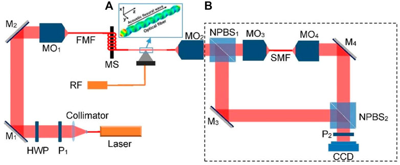
FIGURE 1. Experimental setup of the optical vortex generation and examination. (A) Example for the acoustic flexural wave F11 mode propagating along the unjacketed fiber. (B) Modified Mach–Zehnder interferometer. P, polarizers; HWP, half-wave plate; M, mirrors; MO, micro-objectives; FMF, few-mode fiber; MS, mode stripper; RF, radio frequency; NPBS, non-polarization beam splitters; SMF, single-mode fiber; CCD, charge-coupled device.
By adjusting the input polarization state through P1 and tuning the frequency of RF driving signal applied to the acoustic transducer, the HEx/y11 mode of the input beam is converted to the HEeven/odd21 when the phase matching condition is satisfied. The generated vortex mode from the FMF output terminal is collimated by MO2 and then divided into two parts by a non-polarization beam splitter (NPBS1). Among them, one part passing through the NPBS1 is coupled into a segment of 630 HP fiber to convert the vortex mode back to a fundamental mode because the 630 HP single-mode fiber (SMF) only allows the fundamental mode to pass through. Then, the output light from 630 HP fiber is collimated to a parallel Gaussian beam by MO4, which is the reference beam. The optical vortex mode reflected by NPBS1 and the reference beam are combined with NPBS2 and form the interference patterns. The polarizer P2 is used to convert both the vortex beam and reference beam to be linearly polarized.
4 Experiment results and discussion
First, we record the background hologram of the measure section when the RF is turned off. In other words, optical vortex does not exist yet. Then, the input polarization state and the frequency of RF driving signal are adjusted. A Y-shaped interference fringe appears as shown in the amplified section of Figure 2A. The holograms are continuously recorded at a rate of 15 frames per second (FPS). Figures 2A,B show the holograms of the vortex beam and background beam, respectively. Accordingly, the spatial spectra of the holograms are shown in Figures 2C,D, where the rectangle region represents a frequency selective filter window. Based on double-exposure digital holography, two holograms are reconstructed and the phase distributions can be obtained according to Eq. (5). After the hologram of the background beam is recorded, the changes in the phase map can be calculated in real time along with the experimental process. The wrapped phase maps of the vortex beam and background beam are shown in Figures 2E, F. The vortex phase with no aberration obtained by Eq. (5) is shown in Figure 2G.
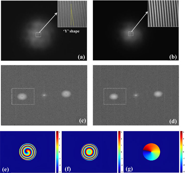
FIGURE 2. Holograms, spatial spectra, and reconstructed phase maps of vortex and background beams. (A) Hologram of the vortex beam, (B)hologram of the background beam, (C) spatial spectra for (A), (D) spatial spectra for (B), (E) wrapped phase of the vortex beam, (F) wrapped phase of the background beam, and (G) unwrapped phase of the vortex beam.
By serializing these phase maps over time, the distribution and evolution of the optical vortex can be shown in the form of a movie (Supplementary Video S1). A sequence of the holograms of ±1-order vortex modes is shown in Figures 3A–D,I–L, respectively. Accordingly, two-dimensional phase distributions of ±1-order vortex modes are shown in Figures 3E–H,M–P, where each picture represents the phase distribution at a certain moment. In Figure 3, the time interval between adjacent results is T/4, where T is the period. The phase distribution rotates by π/4 in turn. For ±1-order vortex modes, the phase results are consistent with the time interval.
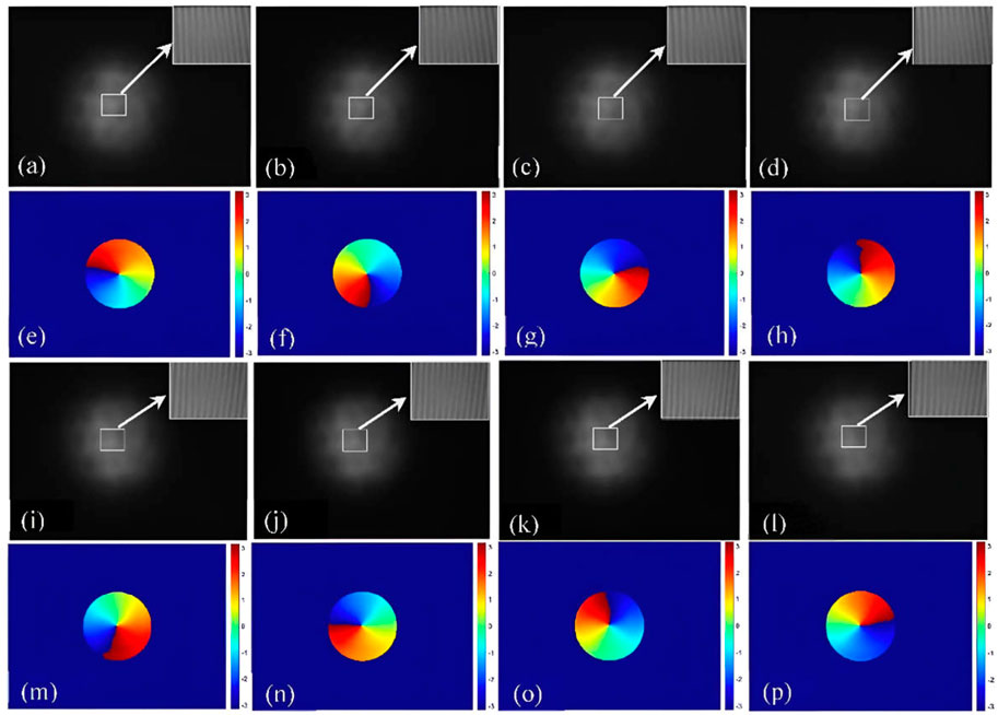
FIGURE 3. Holograms and unwrapped phases of one period. (A)–(D) Holograms of +1-order vortex mode, (E)–(H) phase maps of +1-order vortex mode, (I)–(L) holograms of −1-order vortex mode, and (M)–(P) phase maps of −1-order vortex mode.
Theoretically, when we obtain the vortex beam distribution at time t1, the phase distribution at time t2 is equivalent to that at the propagation distance l = (t2−t1) × c. To verify this idea, the optical vortex is numerically reconstructed with different reconstruction distances. The hologram we used is one frame of a period. The reconstructed results of numerically different reconstruction distances of the ±1-order vortex modes are shown in Figure 4. The reconstruction distances in Figures 4A–H are 0, λ/4, λ/2, and 3λ/4, respectively. Comparing Figure 3 and Figure 4, we find that the phase evolution of the optical vortex numerically reconstructed with different reconstruction distances using a frame of the holograms is the same as that shown in Figure 3. It means that we can reduce the experimental acquisition frequency of optical vortex through numerical reconstruction algorithm and save the acquisition cost while maintaining the advantage of real-time acquisition. It is worth noting that in order to avoid the error caused by too large reconstruction distance, the actual experimental acquisition frequency should be higher than 1/T.
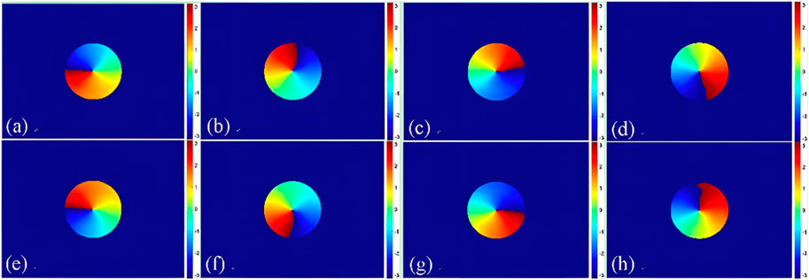
FIGURE 4. Unwrapped phase reconstructed by different reconstruction distances. (A)–(D) +1-order vortex mode phases and (E)–(H) −1-order vortex mode phases.
5 Conclusion
The real-time phase distribution and dynamic evolution of the optical vortex generated by an acoustically induced fiber grating is displayed and analyzed via digital holography. The numerically different-reconstruction-distance reconstructed results are conforming to the experiment results in different times. The real-time visualization idea of optical vortex is feasible by digital holography with limited acquisition frequency. Future experiments will include the high-order vortex modes.
Data availability statement
The original contribution presented in the study is included in the article/Supplementary Material; further inquiries can be directed to the corresponding authors.
Author contributions
JDo and JDi conceived and supervised the project. HQ and KW performed experiments and data analysis. XL and KW contributed to data analysis. KW, JDo and JDi wrote the draft of the manuscript. All the authors edited the manuscript. All authors contributed to the article and approved the submitted version.
Funding
This research was supported by the National Key R and D Program of China (No. 2021YFB2900900), National Natural Science Foundation of China (No. 62075183), and Guangdong Introducing Innovative and Entrepreneurial Teams of “The Pearl River Talent Recruitment Program” (Nos 2021ZT09X044 and 2019ZT08X340).
Conflict of interest
The authors declare that the research was conducted in the absence of any commercial or financial relationships that could be construed as a potential conflict of interest.
Publisher’s note
All claims expressed in this article are solely those of the authors and do not necessarily represent those of their affiliated organizations, or those of the publisher, the editors, and the reviewers. Any product that may be evaluated in this article, or claim that may be made by its manufacturer, is not guaranteed or endorsed by the publisher.
Supplementary material
The Supplementary Material for this article can be found online at: https://www.frontiersin.org/articles/10.3389/fphy.2023.1190616/full#supplementary-material
References
1. Zhan QW. Cylindrical vector beams: From mathematical concepts to applications. Adv Opt Photon (2009) 1(1):1–57. doi:10.1364/aop.1.000001
2. Hancock SW, Zahedpour S, Goffin A, Milchberg HM. Free-space propagation of spatiotemporal optical vortices. Optica (2019) 6:1547–53. doi:10.1364/optica.6.001547
3. Shen Y, Wang X, Xie Z, Min C, Fu X, Liu Q, et al. Optical vortices 30 years on: OAM manipulation from topological charge to multiple singularities. Light Sci Appl (2019) 8:90–29. doi:10.1038/s41377-019-0194-2
4. Padgett M, Bowman R, Tweezers with a twist. Nat Photon (2011) 5(6):343–8. doi:10.1038/nphoton.2011.81
5. Nakajima K, Tsujimura T, Doi K, Kawano SJAo, Visualization of optical vortex forces acting on Au nanoparticles transported in nanofluidic channels. ACS Omega (2022) 7:2638–48. doi:10.1021/acsomega.1c04855
6. Vicidomini G, Bianchini P, Diaspro AJNm., STED super-resolved microscopy. STED super-resolved Microsc (2018) 15:173–82. doi:10.1038/nmeth.4593
7. Thidé B, Then H, Sjöholm J, Palmer K, Bergman J, Carozzi TD, et al. Utilization of photon orbital angular momentum in the low-frequency radio domain. Phys Rev Lett (2007) 99(8):087701. doi:10.1103/physrevlett.99.087701
8. Wang Y, Ge Y, Chen Z, Liu X, Pu J, Liu K, et al. Techniques Broadband high-efficiency ultrathin metasurfaces with simultaneous independent control of transmission and reflection amplitudes and phases," (2021) 70. 254–63.
9. Yan Y, Xie G, Lavery MPJ, Huang H, Ahmed N, Bao C, et al. High-capacity millimetre-wave communications with orbital angular momentum multiplexing. Nat Commun (2014) 5:4876. doi:10.1038/ncomms5876
10. Leach J, Jack B, Romero J, Jha AK, Yao AM, Franke-Arnold S, et al. Quantum correlations in optical angle-orbital angular momentum variables. Science (2010) 329(5992):662–5. doi:10.1126/science.1190523
11. Bhattacharjee A, Joshi MK, Karan S, Leach J, Jha AKJSA, Propagation-induced revival of entanglement in the angle-OAM bases. Sci Adv (2022) 8:eabn7876. doi:10.1126/sciadv.abn7876
12. Wei G, Wang P, Liu Y, Phase retrieval and coherent diffraction imaging by a linear scanning pinhole sampling array. Opt Commun (2011) 284(12):2720–5. doi:10.1016/j.optcom.2011.01.059
13. Dudley A, Milione G, Alfano RR, Forbes A, All-digital wavefront sensing for structured light beams. Opt Express (2014) 22(11):14031–40. doi:10.1364/oe.22.014031
14. Zhang Z, Dong F, Qian K, Zhang Q, Chu W, Zhang Y, et al. Real-time phase measurement of optical vortices based on pixelated micropolarizer array. Opt express (2015) 23(16):20521–8. doi:10.1364/oe.23.020521
15. Lu X, Zhao C, Shao Y, Zeng J, Konijnenberg S, Zhu X, et al. Phase detection of coherence singularities and determination of the topological charge of a partially coherent vortex beam. Appl Phys Lett (2019) 114:201106. doi:10.1063/1.5095713
16. Fratz M, Seyler T, Bertz A, Carl DJLAM, Digital holography in production: An overview. gxjzz (2021) 2:134–295. doi:10.37188/lam.2021.015
17. Osten W, Faridian A, Gao P, Körner K, Naik D, Pedrini G, et al. Recent advances in digital holography [Invited]. Recent Adv digital holography (2014) 53:G44–G63. doi:10.1364/ao.53.000g44
18. Zhang M, Liu J, Dou J, Zhang J, Zhang L, Di J, et al. Simultaneous measurement of near-water-film air temperature and humidity fields based on dual-wavelength digital holographic interferometry. Opt Express (2022) 30:17278–89. doi:10.1364/oe.457640
19. Gao P, Yuan C, Resolution enhancement of digital holographic microscopy via synthetic aperture: A review. Light: Adv Manufacturing (2022) 3(1):105–16. doi:10.37188/lam.2022.006
20. Dou J, Dai S, Dong C, Zhang J, Di J, Zhao J, Dual-channel illumination surface plasmon resonance holographic microscopy for resolution improvement. Opt Lett (2021) 46:1604–7. doi:10.1364/ol.419337
21. Shaked NT, Micó V, Trusiak M, Kuś A, Mirsky SKJAi. O, Photonics . Off-axis digital holographic multiplexing for rapid wavefront acquisition and processing. Adv Opt Photon (2020) 12:556–611. doi:10.1364/aop.384612
22. Kumar M, Matoba O, Quan X, Rajput SK, Awatsuji Y, Tamada YJAO, Single-shot common-path off-axis digital holography: Applications inbioimaging and optical metrology [invited]. Appl Opt (2021) 60:A195–A204. doi:10.1364/ao.404208
23. Wang K, Dou J, Kemao Q, Di J, Zhao JJOL, Y-Net . Y-net: A one-to-two deep learning framework for digital holographic reconstruction. Opt Lett (2019) 44:4765–8. doi:10.1364/ol.44.004765
24. Haakestad MW, Skaar J, Slow and fast light in optical fibers using acoustooptic coupling between twoco-propagating modes. Opt Express (2009) 17(1):346–57. doi:10.1364/oe.17.000346
25. Birks TA, StRussell PJ, Culverhouse DO, The acousto-optic effect in single-mode fiber tapers and couplers. J Lightwave Technol (1996) 14(11):2519–29. doi:10.1109/50.548150
26. Zhao J, Liu X, Fiber acousto-optic mode coupling between the higher-order modes with adjacent azimuthal numbers. Opt Lett (2006) 31(11):1609–11. doi:10.1364/ol.31.001609
27. Erdogan T, Cladding-mode resonances in short- and long-period fiber grating filters. J Opt Soc Am (1997) A14(8):1760–73. doi:10.1364/josaa.14.001760
28. Kim BY, Engan HE, Shaw HJ, Blake JN, All-fiber acousto-optic frequency shifter. Opt Lett (1986) 11(6):389–91. doi:10.1364/ol.11.000389
29. Cuche E, Bevilacqua F, Depeursinge C, Digital holography for quantitative phase-contrast imaging. Opt Lett (1999) 24(5):291–3. doi:10.1364/ol.24.000291
30. Dou J, Ma C, Wang K, Di J, Zhang J, Zhao JJOL, Light-field focusing and modulation through scattering media based on dual-polarization-encoded digital optical phase conjugation. Opt Lett (2022) 47:2738–41. doi:10.1364/ol.461029
Keywords: optical vortex, digital holography, real-time phase measurement, numerically reconstructed, acoustically induced fiber grating
Citation: Qiu H, Liu X, Wang K, Dou J, Di J and Qin Y (2023) Real-time phase measurement of optical vortex via digital holography. Front. Phys. 11:1190616. doi: 10.3389/fphy.2023.1190616
Received: 21 March 2023; Accepted: 02 May 2023;
Published: 19 May 2023.
Edited by:
Peng Gao, Xidian University, ChinaReviewed by:
Wenjing Zhou, Shanghai University, ChinaJunwei Min, Xian Institute of Optics and Precision Mechanics (CAS), China
Copyright © 2023 Qiu, Liu, Wang, Dou, Di and Qin. This is an open-access article distributed under the terms of the Creative Commons Attribution License (CC BY). The use, distribution or reproduction in other forums is permitted, provided the original author(s) and the copyright owner(s) are credited and that the original publication in this journal is cited, in accordance with accepted academic practice. No use, distribution or reproduction is permitted which does not comply with these terms.
*Correspondence: Jiazhen Dou, amlhemhlbmRvdUBnbWFpbC5jb20=; Jianglei Di, amlhbmdsZWlkaUBnZHV0LmVkdS5jbg==