 Cheng Yu†
 Ya Zhu†
 Wei Zhang*Jie YangYongzhou He
 Tingting Zhen
 Tao LiuYangyang LeiQibing YuanDao YuanYongmei WenRongbing DengZhiqiang JiangHaixiao Deng
 Bo Liu*Dong Wang
- Shanghai Advanced Research Institute, Chinese Academy of Sciences (CAS), Shanghai, China
The Shanghai high-repetition-rate XFEL and extreme light facility (SHINE) plans to install several elliptically polarizing undulators (EPUs) as afterburners behind the planar undulator section to obtain nearly saturated circularly polarized free-electron laser (FEL) radiation. Therefore, the SHINE R&D project needs to develop a 4-m-long EPU with an effective magnetic field of 1.5 T, a period of 68 mm, and a minimum gap of 3 mm. A magnetic force compensation EPU prototype has recently been built and tested at the Shanghai Synchrotron Radiation Facility (SSRF) based on the addition of permanent magnets. This prototype can realize magnetic compensation under various polarization modes in all working gaps, thereby reducing the deformation of the girders and maintaining sufficient rigidity of the mechanical structure. A girder deformation monitoring system was established to obtain real force compensation feedback. The final magnetic field measurement results meet the physical requirements, and the proposed scheme can be used as an alternative to the EPU with a high magnetic field and large magnetic force.
1 Introduction
The Shanghai high-repetition-rate XFEL and extreme light facility (SHINE) is currently under construction. Based on the 8-GeV CW superconducting RF (SCRF) LINAC [1, 2], SHINE can generate 0.4–25 keV photon radiation from three undulator lines (Figure 1). SHINE has three beam lines and nine experimental stations, with high peak brightness and average brightness, a high repetition rate (up to 1 MHz), and femtosecond-level super-fast pulse characteristics. Additionally, SHINE has a nano-level spatial resolution and femtosecond-level ultrafast temporal resolution. The total length of the SHINE project is approximately 3.2 km, including the accelerator, undulators, beam line tunnels, experiment halls, low-temperature factory, and auxiliary facilities. The free-electron laser (FEL) comes from the coherent superposition of the radiation and the coherent amplification of the electromagnetic field. To keep most of the electrons in an energy-releasing state, a fixed-phase relationship is required between the electrons and the radiation based on the well-known resonance condition [3] given as follows:
The FEL wavelength
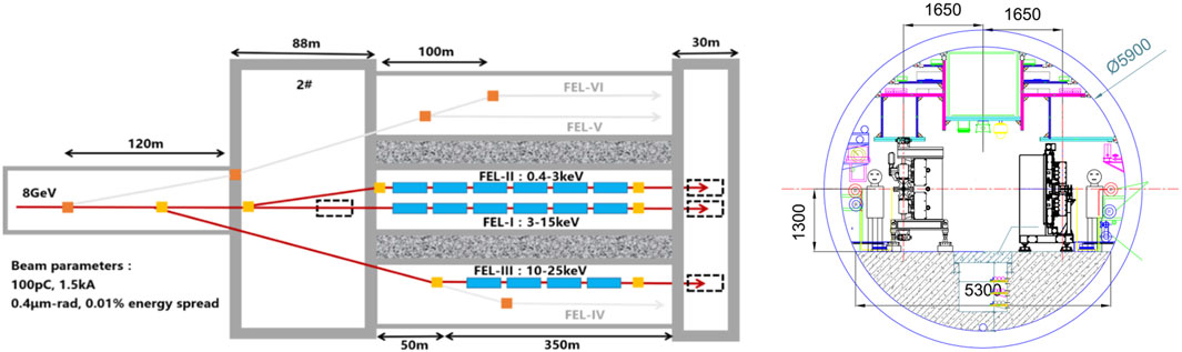
FIGURE 1. Layout of the undulator lines of the SHINE project. Left: undulator system. Right: FEL-I&II tunnel.
In the SHINE project, FEL-II produces soft X-rays from 0.4 to 3 keV with planar undulators, which can easily produce a high magnetic field strength and are both conducive to FEL gain and cost-efficient. The planar undulator shows a better perfect magnetic field performance than the EPU, which is beneficial for FEL amplification saturation. The X-ray FEL device with planar undulators only produces linearly polarized light, and the polarization state cannot be changed. Partly as a result, a polarization control scheme is planned using EPUs as an afterburner. The main parameters of the EPU are shown in Table 1. The period length is 68 mm, and the total length is 4 m. The effective magnetic field is required to reach 1.5 T for horizontal, vertical, and circular polarization, and the root mean square (RMS) phase error requirement is less than 12°.
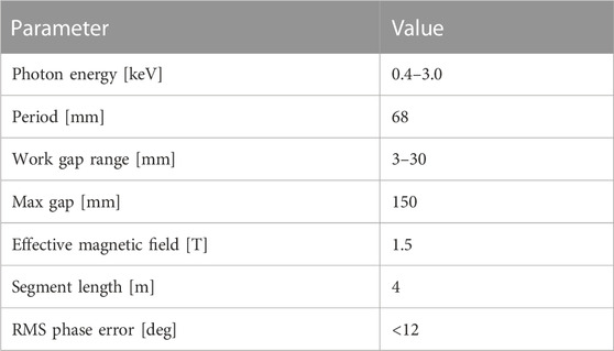
TABLE 1. Main parameters of the FEL-II EPU (EPU68 prototype).
2 Selection strategies for the EPU
Among the variable polarizing undulators (VPUs) running on most third-generation storage ring light sources, the APPLE II [4] configuration can provide the strongest magnetic field. An APPLE II undulator consists of two pairs of diagonal Halbach I magnet arrays, in which at least one pair of diagonal magnet arrays can be moved in longitudinal synchronization to control the polarization mode, and the distance moved is called the phase. Later, an inclined mode was proposed, whereby a set of diagonal girders moved the same phase in the opposite direction, and the axis of polarization of linear polarized light would tilt within 0° and 90°. In contrast to the earlier proposed Apple I configuration [5, 6], the magnetization direction of the Apple II configuration is optimized to be completely perpendicular, which provides a higher on-axis magnetic field in the linear polarization mode and a larger uniform field region. However, this large-field region and the matching rectangular vacuum chamber with a wide transverse dimension are unnecessary for the single-pass beam in the FEL device. In 2004, Bahrdt [7] proposed the Apple III configuration, which had three differences to the APPLE II configuration: 1) the vertical gap was compressed, 2) the magnets were chamfered to accommodate the circular vacuum chamber, and 3) the easy axis of the vertical magnets was rotated by 45°. These improvements allowed for a 40% increase in the magnetic field strength when a vacuum chamber of the same size is configured. Figure 2 shows the direction of easy-magnetization axes (one-way black arrow) and girder movement (two-way orange and yellow arrows) when these structures are in phase zero.
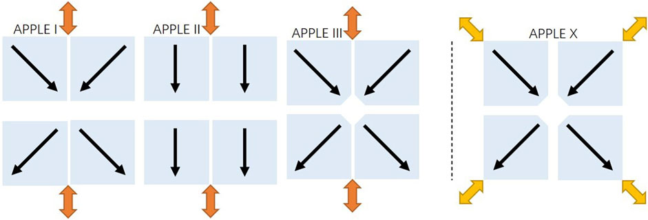
FIGURE 2. From left to right: cross sections of the APPLE I, II, III, and X configurations. The four Halbach magnet arrays of the three configurations on the left are located on two girders, i.e., the vertical gap is adjustable, while the transverse slit is fixed. The latest APPLE X configuration has four independent magnet arrays that move radially.
Unlike the aforementioned variable-gap APPLE-type undulators (VGUs), the first choice for a high-field EPU is a fixed-gap design, called Delta, which has a more compact structure [8–10]. This fixed-gap design ensures the magnetic arrays are always kept at the minimum gap, although the permanent magnets are likely to be damaged by radiation. The magnetic measurement is very difficult to complete, especially for a long undulator. The magnetic arrays cannot be fully opened for the initial commissioning of the accelerator, but the minimum gap can be determined experimentally. In addition, it has recently been reported that phase-shift undulators have an intrinsic problem with field gradients [11].
The second solution for a small-gap EPU is to place the magnets in vacuum based on force compensation technology. This enables a compact structure to be achieved within a chamber for high-magnetic field VGUs. During the past 10 years, different types of magnetic force compensations for planar undulators have been implemented or prototyped [12, 13] at several SR facilities. To obtain a high-field EPU, the magnetic force compensation technology is now attractive to some facilities. Based on the traditional APPLE II configuration, in 2019, Bahrdt and Grimmer [14] proposed a design to overcome difficulties in realizing APPLE-type in-vacuum undulators (IVUs), which are based on magnetic force compensation with additional magnetic arrays, and facilitate the phasing operation in the undulator. Recently, they proposed the development of a cryogenic APPLE undulator [15] using the same scheme. In 2020, Kinjo and Tanaka [16] presented a spin-EPU structure for the realization of polarization control in IVUs. Although the available polarization state was limited compared to the conventional APPLE undulators, the structure and operation of the undulator based on the proposed scheme were much simpler, and it could, therefore, be easily implemented in IVUs. Additionally, the magnetic force in the proposed undulator could be reduced to a negligible level by carefully optimizing the dimensions and positions of magnet arrays, without any special equipment.
The third strategy to develop a high-field small-vertical gap EPU is to increase the rigidity of each magnet array girder by independently using a strong carrier beam with the APPLE X structure proposed at the Paul Scherrer Institute (PSI) in 2016 [17, 18]. The four girders of the APPLE X undulator require an independent motion system and a mechanical support beam. The magnetic design is fully symmetric for all gaps and uses Delta-type magnets with 45° magnetization. The magnetic measurement is conducted with a set of hall probes in the minimal vertical gap. The APPLE X undulator can generate gradients for the ultra-high bandwidth mode [19]. It is notable that this structure has the benefit of being without longitudinal forces in the inclined mode. The disadvantage is that the section size of the APPLE X structure is larger than that of the traditional vertical gap movement APPLE structure.
The magnetic gap of the SHINE project 4-m-long EPU needs to be reduced to 3 mm to achieve the required magnetic field. For a 3-mm magnet vertical gap, an IVU may be suggested if the cost and complexity are not considered. Due to the limited number of rigid connections, systematic gap errors can easily arise for a small-gap IVU. Micron-level deformation will lead to a very large magnetic field variation, which is bound to affect the radiation phase error. During the transition of different polarization modes, the magnitude and direction of the magnetic force of the magnet arrays change synchronously. The deformation variation from horizontal to vertical polarization is very large, and the magnetic field performance is very difficult to guarantee for different polarizations.
To expand the photon energy range and add as much polarization control of FEL as possible, two undulator lines in one tunnel is an effective approach. This has been shown to greatly improve the efficiency of the FEL device. In the SHINE project, FEL-I and FEL-II are being constructed in the same tunnel, as shown in Figure 1. The size of accelerator equipment should meet the horizontal width limit of less than 1,200 mm, and a sufficient installation path needs to be reserved.
Based on the aforementioned analysis, we chose the traditional C-type and in-air mechanical structure to reduce the cost and complexity, adopted the APPLE III magnet configuration to meet the requirement of a 1.5-T effective field for vertical linear polarization, and used the three-dimensional magnetic force compensation scheme to reduce the overall size of the undulator. In Sections 3 and 4, the magnet design, including the force compensation, is presented to explain the crucial points for the EPU68 prototype. In Sections 5 and 6, the mechanical structure, analysis, and comparison results of the force compensation are displayed. In Section 7, magnetic field measurements of the EPU68 prototype are presented.
3 Magnetic design
The APPLE III magnet configuration was used to achieve the required magnetic field performance for the EPU68 prototype. The overall structure, including the additional magnets, is shown in Figure 3, and the coordinate system described in this article is also represented. The red and blue magnets in the center are called functional magnets (FMs) in this paper. The minimum gap is the same as the slit, both of which are 3 mm. The four groups of green Halbach I magnet pairs around them are the compensation magnet (CM) array, which are divided into left/right CM and top/bottom CM pairs. The EPU68 prototype uses neodymium–iron–boron (NdFeB) permanent magnets (N38EH grade or above) as the magnetic field source of the undulator. The minimum remanence (Br) is at least 1.25 T, the intrinsic coercive field (Hcj) associated with the magnetization curve is not less than 2,400 kA/m, and Hk is not less than 2,300 kA/m at 25°C. The size of the FMs is 25 × 25 mm2, with a 3-mm chamfer near the electron beam position. The horizontal slit between the fixed and moving girder is the same as the vertical gap. Around the center, there is a rhombus-shaped space for a vacuum chamber. The effective field can reach 1.5 T (peak field 1.47 T) in the linear polarization mode and 1.5 T (peak field 1.06 T both in X and Y directions) in the circular polarization mode.
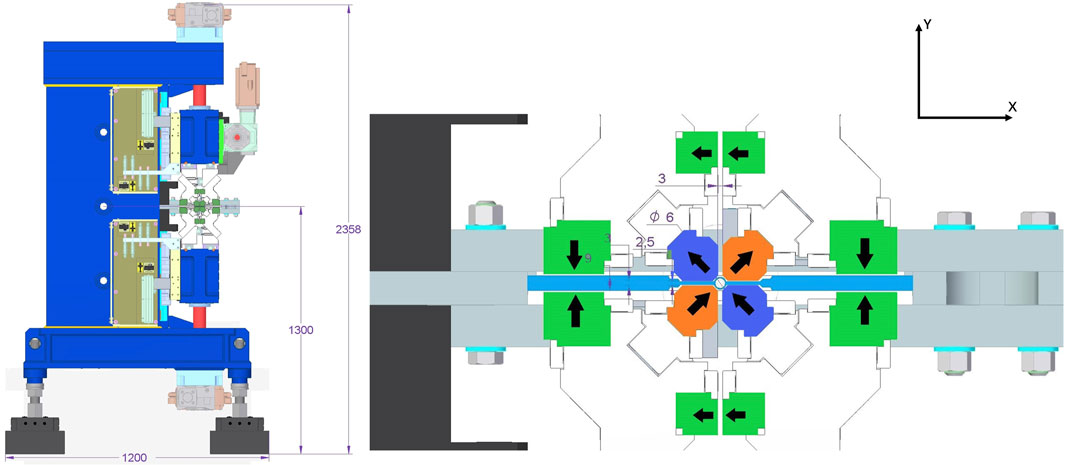
FIGURE 3. The undulator consists of four FM arrays (orange and blue) and eight CM arrays (green).
Considering the magnetic field measurement requirements of the EPU68 prototype and the design difficulty of the vacuum chamber, the vacuum chamber was made of stretched aluminum placed in the middle of the gap, as shown in Figure 3. The requirement for a minimum gap of 3 mm resulted in great difficulty in the design and processing of the vacuum chamber. The vertical gap of the CM arrays for vertical magnetic compensation was, therefore, relaxed to 10 mm. The size of the left/right CMs was increased to achieve better results. The prototype magnet parameters are shown in Table 2. For all FMs, the magnetization angle was precisely perpendicular to the base faces, the maximum deviation angle was less than ±1.0°, and the magnetization uniformity was less than 1.0%. For all CMs, the specifications of the required magnetization angle and uniformity are reduced to ±2.0° and 2.0%, respectively.

TABLE 2. Main design parameters of the EPU68 prototype.
4 Force compensation by CMs
The EPU68 prototype required an effective magnetic field of 1.5 T for both linear and circular polarizations, as shown in Figure 4, which is an unusually high-magnetic field design for an EPU in the world. The magnetic force between the upper and lower girders of the 4-m-long undulator was nearly 8 tons at the minimum gap. Under such a large magnetic force, the forced deformation of the girders had a significant effect on the magnetic field quality of the prototype. For the EPU68 prototype, not only did the magnetic force for each girder change when the magnetic gap changed but also at the same magnetic gap, the magnetic force is also changed from −4 to 2 tons during phase shifts. This is also shown in Figure 4. With a change in the direction of the magnetic force, the attractive force between the back beams became a repulsive force when the phase shift was half period. The decrease in the mechanical deformation of the magnet girder under the action of a magnetic force is the key to the quality assurance of magnetic field performance. Due to the CMs, the force variation between shift = 0 and 34 mm was successfully reduced from 60 to 6 kN for both the vertical and horizontal directions, as shown in the right side of Figure 4.
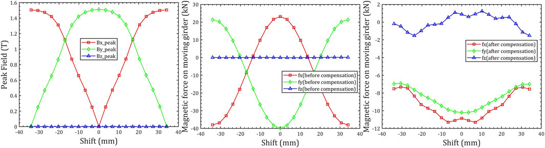
FIGURE 4. Shift-dependent variation parameters at the minimum gap: Bx_peak/fx (red), By_peak/fy (green), and Bz_peak/fz (blue). Left: magnetic field. Center: magnetic force on the moving girders before compensation. Right: magnetic force on the moving girders after compensation, calculated with the RadiaCode [20].
To ensure the high quality of the undulator magnetic field and the safety and stability of the undulator mechanical system, the rigidity and stability of the beams can be increased; however, this would make the design of the entire mechanical structure of the undulator more complex, larger, and much more expensive. Another option is the addition of two magnet arrays on each girder to produce opposite forces in the vertical and horizontal directions, as shown in Figure 3. Depending on the CM arrays, the forces acting on the moving girders can be reduced to a very low value. The magnetic force variation of each moving girder had a very satisfactory result of less than 6 kN at the minimum gap of 3 mm during the phase change between the zero phase and half-period phase. The magnetic force variation during the gap opening of each moving girder was reduced to less than 10 kN, which is also shown in Figure 5. To visually compare the force of each magnet array, the force direction of all arrays in the different phase shifts at the minimum gap is shown in Figure 6. The value of the force at the maximum gap of 150 mm is provided for comparison in Table 3.
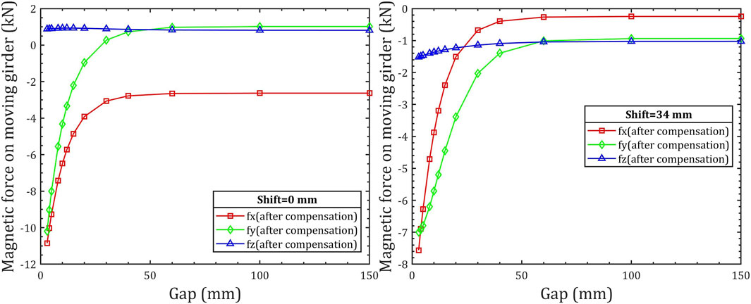
FIGURE 5. Magnetic force on a moving girder after compensation at different gaps: fx (red), fy (green), and fz (blue). Left: shift = 0 mm. Right: shift = 34 mm.
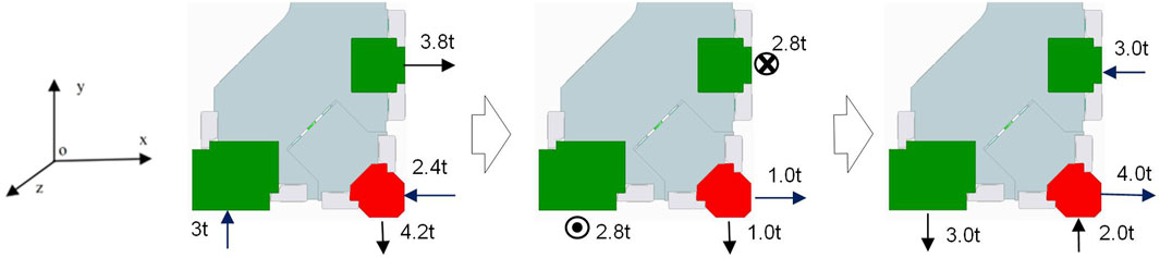
FIGURE 6. Schematic representation of the force loads on a moving girder at the minimum gap of 3 mm (shift = 0, 17, 34 mm).
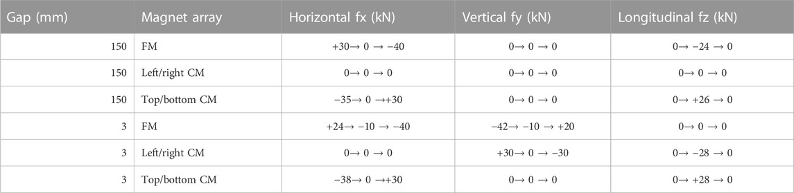
TABLE 3. Three forces acting on different magnet arrays of a moving girder at the minimum and maximum gaps. (For example: when the shift changed by 0, 17, and 34 mm, the horizontal force fx marked as +30→ 0 → −40 at the maximum gap of 150 mm).
5 Mechanical structure and motion control
Figure 7 shows the structure of the EPU68 prototype, illustrating the support structure and drive systems. The support structure had a “C” frame design, which was convenient for the magnetic measurements and device installation. The adjusted base with six kinematic floor mounts had a welded steel structure, and the adjusted ranges for z direction were ±6 mm and ±10 mm in the x and y directions, respectively. Two vertical columns with two horizontal columns to strengthen the rigidity were mounted to the base. Four cube steel tubes, which connect the base and vertical columns, further strengthened the stability of the support structure. The vertical columns supported four roller screw assemblies, which enabled the vertical movement of the upper and lower beams. The support frame and the backing beams were made of cast iron to ensure a small mechanical deformation during phase changes. The fixed girders and moving girders were made of an aluminum alloy. The fixed girder supported the moving girder with two sets of crossed roller slides. The moving girder can move along the two guides mounted between the backing beam and fixed girder.
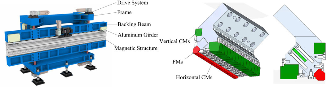
FIGURE 7. Mechanical structure of the EPU68 prototype and magnet keeper.
The three magnet arrays of each girder were kept in the same massive magnet keeper, which was made of an aluminum alloy. There was only a shimming strategy for moving magnets parallel to the magnetization direction. The magnet position was adjusted by rotating the lock nuts. The image on the right side of Figure 7 shows the magnet keeper layout, which was used in FEM studies to optimize the geometries. The magnet keepers were fixed to the girders by positioning pin holes and bolts. A shimming displacement of 50 μm resulted in a local field change of 35 Gs cm at a gap of 3 mm. The maximum allowed shimming range was ±100 μm.
The motion control mainly focused on the 1-μm precision magnet movement, including gap adjustment, taper adjustment, and shift adjustment, for the full range of operational gap values. The control tasks consisted of the motion control of all the aforementioned movements, monitoring the real-time gap position in the upstream and downstream through position feedback derived from the linear absolute encoders (LAEs) with 5-nm resolution, offering remote access for the Experimental Physics and Industrial Controls System (EPICS) toolkit via Ethernet, as well as the machine protection system (MPS) and personal protection system (PPS) interlock interfaces for the upper-level protection system of the interlock system.
6 Force compensation performance
6.1 Magnetic measurement bench (MMB) and the girder deformation monitoring system
The Shanghai Synchrotron Radiation Facility (SSRF) has a set of three-dimensional MMB, which consists of a cable dragging system, multi-axis motion system (a Hall probe is installed at the front end and can be fine-tuned to eliminate the attitude error of the probe), and control system, as shown in Figure 8. The z-axis measuring range is 6,500 mm, and both the x-axis and y-axis measuring ranges are 300 mm. The probe is a H3A Hall probe (Senis AG, Zug, Switzerland), which has a small planar Hall effect, a measuring accuracy of 0.1 G s, and a measuring range of ±1.9 T, thus covering the magnetic field range of the EPU68 prototype.
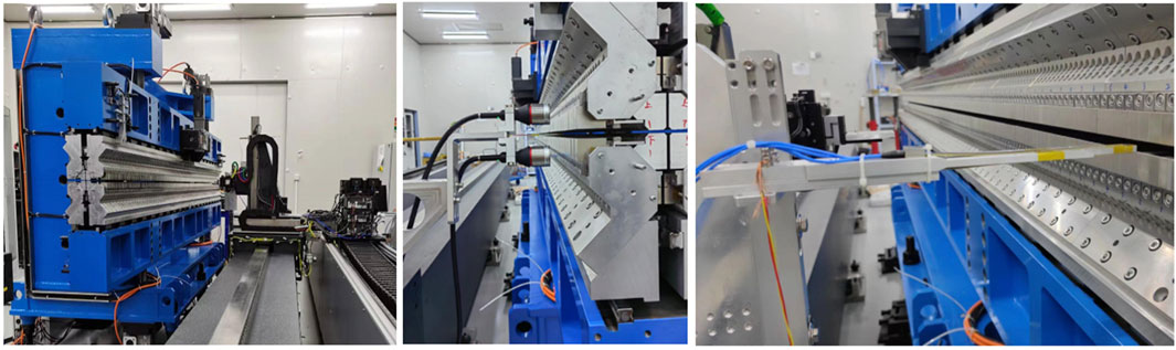
FIGURE 8. Left: MMB. Center: KEYENCE laser displacement sensors. Right: capacitance transducer.
The MMB provided support for a capacitance transducer to measure the vertical displacement along the magnet surface. The relative deformation of the vertical and circular polarization compared to the horizontal polarization (shift = 0 mm) could be easily obtained from the measurement of the different phase shifts. Additionally, two KEYENCE (Osaka, Japan) laser displacement sensors were installed in the MMB support to scan for horizontal displacement and detect the deformation of the different polarizations. Both the capacitance transducer and KEYENCE laser displacement sensors used in the MMB system showed a repetitive performance of less than 5 μm, which was acceptable for the displacement measurements.
6.2 Measurement from gap = 0–150 mm at shift = 0 mm
When the phase shift was zero, there was no longitudinal force acting on the moving girder. As shown in Figure 5, with the force compensation of the CMs, there was just a 12-kN vertical force variation (horizontal force variation 9 kN) between the minimum and maximum gaps. For the moving girder mounted between the backing beam and fixed girder by the two set guides, the horizontal deformation variation between the maximum and minimum gaps along the Z-axis was small and trended smoothly. In the MMB laboratory, we set the phase to zero and measured just the vertical displacement with the capacitance sensor at the minimum and maximum magnetic gaps to detect the vertical deformation. The experimental test data revealed a 20-μm variation deformation that appeared during the gap changes at shift = 0 mm, as shown in Figure 9.

FIGURE 9. Vertical deformation variation at shift = 0 mm when the gap changed from 3 to 150 mm.
6.3 Measurement from shift = 0–34 mm at the maximum gap
As shown in Table 3, there was no vertical force acting on the moving girders during phase shifting at a maximum gap of 150 mm; the horizontal and longitudinal force variations were 5 kN and 2 kN, respectively. We mainly measured the horizontal deformation of the moving girder. The measured horizontal deformation variation was approximately 15 μm when comparing shift = 34 mm with shift = 0 mm, and the measured horizontal deformation variation was approximately 20 μm when comparing shift = 17 mm with shift = 0 mm. The trend of the horizontal deformation measurement results was basically consistent with that of the simulation results. The amplitude was slightly larger than the simulation results after force compensation, and the compensation effect was notable, as shown in Figure 10(2) and 10(3).
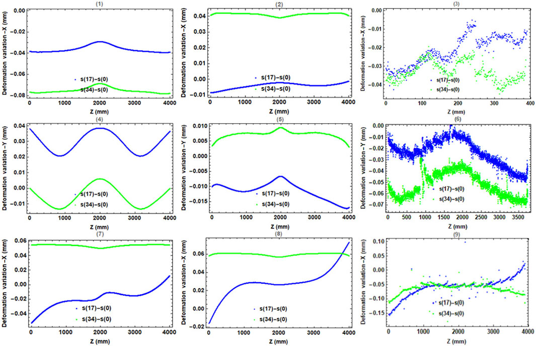
FIGURE 10. Deformation variation of a moving girder between different shifts. (1), (2), and (3): horizontal deformation at the maximum gap of 150 mm. (4), (5), and (6): vertical deformation at the minimum gap of 3 mm. (7), (8), and (9): horizontal deformation at the minimum gap of 3 mm. Left: FEM simulation results before compensation. Middle: FEM simulation results after compensation. Right: test results.
6.4 Measurement at the minimum gap
At a minimum gap of 3 mm, the vertical displacement for shifts = 0, 17, and 34 mm was measured using a capacitance sensor probe. Compared with shift = 0 mm, the deformation of the magnet top surface changed by approximately 30 μm for shift = 34 mm and by approximately 40 μm for shift = 17 mm. Although the results were much smaller than the simulation value before force compensation, they were still much larger than the simulation result after force compensation. The test results of the vertical deformation variation of the magnet were basically consistent with the trend of the simulation results, but the results were on the large side. As shown in Figure 10, a similar result was achieved during the horizontal deformation variation measurement from shift = 0 mm to shift = 34 mm. Compared with shift = 0 mm, the horizontal variation in shift = 17 mm was approximately 150 μm, which was almost twice that of the simulation value when comparing shift = 17 mm with shift = 0 mm. A variation in the inclined deformation along the undulator was observed in both the vertical and horizontal directions.
7 Magnetic measurement results
Considering that the minimum magnetic gap was 3 mm, the quantity and displacement of magnet shimming in the EPU68 prototype are confined-limited. The maximum shimming displacement should be controlled within 0.1 mm; otherwise, the installation of the vacuum chamber becomes difficult. Finally, the effective magnetic field and RMS phase error are shown in Table 4. The RMS phase error was below 6° at vertical polarization for a gap less than 15 mm. The RMS phase error in horizontal polarization is not as good as that in vertical polarization, especially at small gaps less than 5 mm. Unfortunately, the phase error in right hand circular polarization exceeded our target of being within 12°. This problem may be caused by mechanical assembly errors and clearance calibration errors, and surpassed expectations of the deformation variation. An effective magnetic field of 1.5 T was achieved at a gap of 3.4 mm for horizontal polarization and a gap of 3.2 mm for vertical polarization. At a gap of 30 mm, the effective magnetic field is about 0.3 T, which was within the acceptable gap range.
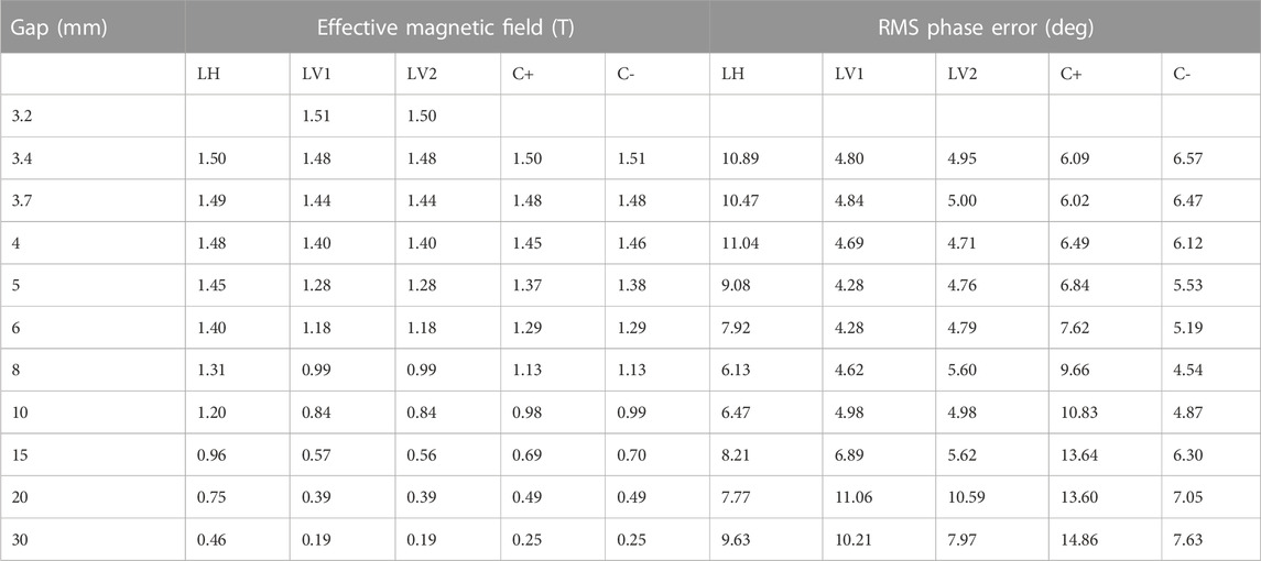
TABLE 4. Magnetic performance in a gap range of 3–30 mm. Different polarization modes: horizontal linear (LH), vertical linear (LV1,2), right-handed circular (C+), and left-handed circular (C-) modes.
8 Transfer of the magnetic axis to mechanical fiducial marks
The small area with a good magnetic field in the vertical direction and the deviation between the mechanical and magnetic centers were sensitive parameters for installation and operation. A magnetic center extraction for the EPU68 prototype was performed after the magnetic field measurement. The magnetic center was defined as the axis formed by the magnetic field shimming on the cross section of this undulator. A pair of magnetic landmarks [21] (MLs) was used to transfer the magnetic axis of the undulator to the mechanical fiducials using a laser tracker system, as shown in Figure 11. The extraction accuracy was better than 0.05 mm.
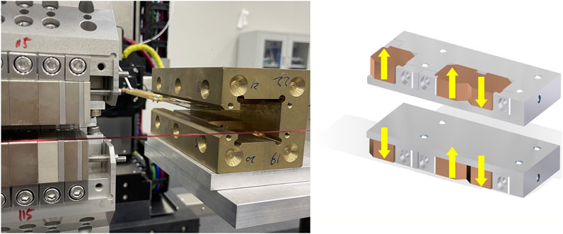
FIGURE 11. MLs were located on both sides of the EPU68 prototype, and the magnetic center of the undulator was determined by two quadrupole (skew and normal quadrupole) fields inside the MLs, as shown in the right side of the figure.
9 Summary
The deformation variation test results during phase shifting at the minimum gap were not as good as that at the maximum gap. There was a relatively large inclined deformation variation when the phase shift ranged from 0 to 17 mm and was then extended to 34 mm. As shown in Figure 6, at the circular polarization mode of shift = 17 mm at the minimum gap, in the cross section of the EPU68 prototype, both the added vertical and horizontal forces of the moving girder composed of three magnet arrays were small. However, the force torque was large, and its direction changed gradually when the phase shifted. Similarly, the added longitudinal force of the moving girder in the electron beam direction was also very small. The longitudinal force torque was largest at shift = 17 mm due to the opposite force directions of the left/right and the top/bottom CMs, leading to a rotated distortion of the whole beam and the generation of a large inclined deformation in both the horizontal and vertical directions. Unfortunately, the simulation of the EPU design did not take into consideration the effect of torque in circular polarization. This was possibly one reason why the horizontal magnetic field was lower than the vertical magnetic field under the same gap. It may also explain why the phase error of horizontal polarization was larger than that of vertical polarization.
A high-magnetic field EPU is critical for the polarization control of high-energy continuous-wave FEL devices. A high magnetic field needs a very small magnetic gap and generates vexatious strong magnetic forces. A massive and reinforced mechanical structure is a popular approach to ensure its rigidity. SHINE-EPU68 adopts the APPLE III magnet configuration with the traditional C-type mechanical structure, and a set of Halbach I magnet arrays was selected to compensate the magnetic forces for FMs, which makes the C-type mechanical structure relatively compact and narrow in horizontal size. It is applicable for the SHINE project two-line tunnel. The deformation test results when a gap opened from 3 to 150 mm at the horizontal polarization indicated a notable vertical force compensation. The horizontal deformation test results of the prototype at the maximum gap showed that the deformation variation during phase shifting had sufficient rigidity, and the magnetic field test results met the physical requirements.
Data availability statement
The raw data supporting the conclusion of this article will be made available by the authors, without undue reservation.
Author contributions
CY and the corresponding author WZ contributed to the magnet design, magnetic measurement, and shimming. YZ, TZ, and RD designed the mechanical structure and conducted the FEM simulation. CY, YZ, and WZ wrote most of the manuscript and contributed to the conception and design of the study. JY and YZ designed the deformation monitoring system. YH contributed to magnet manufacturing. CY, DY, and ZJ conducted the magnetic center extraction. YL and QY designed the control system. YW designed the vacuum chamber. TL contributed to the physical design of the FEL schemes. HD, DW, and the corresponding author BL reviewed the manuscript and supervised the work. All authors contributed to the article and approved the submitted version.
Funding
This work was supported by the Chinese Academy of Science (CAS) Project for Young Scientists in Basic Research (YSBR-042), the National Natural Science Foundation of China (12125508 and 11935020), the Program of Shanghai Academic/Technology Research Leader (21XD1404100), and the Shanghai Pilot Program for Basic Research-CAS, Shanghai Branch (JCYJ-SHFY-2021-010).
Conflict of interest
The authors declare that the research was conducted in the absence of any commercial or financial relationships that could be construed as a potential conflict of interest.
Publisher’s note
All claims expressed in this article are solely those of the authors and do not necessarily represent those of their affiliated organizations, or those of the publisher, the editors, and the reviewers. Any product that may be evaluated in this article, or claim that may be made by its manufacturer, is not guaranteed or endorsed by the publisher.
References
1. Zhao ZT, Wang D, Yin L. SCLF: An 8-GeV CW SCRF Linac-Based X-Ray FEL Facility in Shanghai. Santa Fe, NM: JACoW Publishing (2018). doi:10.18429/JACoW-FEL2017-MOP055
2. Huang N-S, Liu Z-P, Deng B-J, Zhu Z-H, Li S-H, Liu T, et al. The MING proposal at SHINE: Megahertz cavity enhanced X-ray generation. Nucl Sci Tech (2023) 34:6. doi:10.1007/s41365-022-01151-6
3. Schmüser P, Dohlus M, Rossbach J. Undulator Radiation In: GH. Karlsruhe, editors Ultraviolet and Soft X-Ray Free-Electron Lasers. Berlin, Germany: Spring (2009). p. 11–22. doi:10.1007/978-3-540-79572-8
4. Sasaki S. Analyses for a planar variably-polarizing undulator. Nucl Instrum Methods Phys Res Sect Accel Spectrometers Detect Assoc Equip (1994) 347:83–6. doi:10.1016/0168-9002(94)91859-7
5. Sasaki S, Miyata K, Takada T. A new undulator for generating variably polarized radiation. Jpn J Appl Phys (1992) 31:L1794. doi:10.1143/JJAP.31.L1794
6. Sasaki S, Kakuno K, Takada T, Shimada T, Yanagida K, Miyahara Y. Design of a new type of planar undulator for generating variably polarized radiation. Nucl Instrum Methods Phys Res Sect Accel Spectrometers Detect Assoc Equip (1993) 331:763–7. doi:10.1016/0168-9002(93)90153-9
7. Bahrdt J, Frentrup W, Gaupp A, Kuske B, Meseck A, Scheer M. Undulators for the BESSY Soft-X-Ray FEL. Trieste, Italy: JACoW Publishing (2004).
8. Temnykh AB. Delta undulator for Cornell energy recovery linac. Phys Rev Spec Top - Accel Beams (2008) 11:120702. doi:10.1103/PhysRevSTAB.11.120702
9. Nuhn H-D, Anderson S, Bowden G R&D Towards a Delta-type Undulator for the LCLS. New York, NY: JACoW Publishing (2014).
10. Nuhn H-D, Anderson SD, Coffee RN. Commissioning of the Delta Polarizing Undulator at LCLS. Daejeon, Korea: JACoW Publishing (2015). doi:10.18429/JACoW-FEL2015-WED01
11. Schmidt T, Calvi M, Schmitt T, Strocov VN, Zimoch D. Operation experience of the UE44 fixed gap APPLE II at SLS. J Phys Conf Ser (2013) 425:032020. doi:10.1088/1742-6596/425/3/032020
12. Kinjo R, Kagamihata A, Seike T, Kishimoto H, Ohashi H, Yamamoto S, et al. Lightweight-compact variable-gap undulator with force cancellation system based on multipole monolithic magnets. Rev Sci Instrum (2017) 88:073302. doi:10.1063/1.4991652
13. Strelnikov N, Vasserman I, Xu J, Jensen D, Schmidt O, Trakhtenberg E, et al. Vertically polarizing undulator with dynamic compensation of magnetic forces. Phys Rev Accel Beams (2017) 20:010701. doi:10.1103/PhysRevAccelBeams.20.010701
14. Bahrdt J, Grimmer S. In-vacuum APPLE II undulator with force compensation. Taipei, Taiwan: AIP Publishing (2019). p. 030031. doi:10.1063/1.5084594
15. Rial E, Bahrdt J, Grimmer S, Meseck A, Scheer M. Development of a cryogenic APPLE CPMUE15 at BESSY II. J Phys Conf Ser (2022) 2380:012018. doi:10.1088/1742-6596/2380/1/012018
16. Kinjo R, Tanaka T. Undulator configuration for helicity switching in in-vacuum undulators. Phys Rev Accel Beams (2020) 23:020705. doi:10.1103/PhysRevAccelBeams.23.020705
17. Joehri H, Jöhri H, Calvi M, Hindermann M, Huber L, Keller A, et al. Development of the new UE38 Undulator for the Athos Beamline in SwissFEL. Paris, France: JACoW Publishing (2018). doi:10.18429/JACoW-MEDSI2018-TUOPMA03
18. Schmidt T, Calvi M. APPLE X undulator for the SwissFEL soft X-ray beamline athos. Synchrotron Radiat News (2018) 31:35–40. doi:10.1080/08940886.2018.1460174
19. Calvi M, Camenzuli C, Prat E, Schmidt T. Transverse gradient in Apple-type undulators. J Synchrotron Radiat (2017) 24. doi:10.1107/S1600577517004726
20. Chubar O, Elleaume P, Chavanne J. A three-dimensional magnetostatics computer code for insertion devices. J Synchrotron Radiat (1998) 5:481–4. doi:10.1107/S0909049597013502
Keywords: free-electron laser, high magnetic field, elliptically polarizing undulator, force compensation, deformation detection
Citation: Yu C, Zhu Y, Zhang W, Yang J, He Y, Zhen T, Liu T, Lei Y, Yuan Q, Yuan D, Wen Y, Deng R, Jiang Z, Deng H, Liu B and Wang D (2023) Development of an APPLE III undulator prototype with three-dimensional force compensation for SHINE. Front. Phys. 11:1174620. doi: 10.3389/fphy.2023.1174620
Received: 26 February 2023; Accepted: 14 June 2023;
Published: 27 June 2023.
Edited by:
Nicholas Walker, Helmholtz Association of German Research Centres (HZ), GermanyReviewed by:
Mukesh Kumar Pandey, National Taiwan University, TaiwanMaofei Qian, Argonne National Laboratory (DOE), United States
Copyright © 2023 Yu, Zhu, Zhang, Yang, He, Zhen, Liu, Lei, Yuan, Yuan, Wen, Deng, Jiang, Deng, Liu and Wang. This is an open-access article distributed under the terms of the Creative Commons Attribution License (CC BY). The use, distribution or reproduction in other forums is permitted, provided the original author(s) and the copyright owner(s) are credited and that the original publication in this journal is cited, in accordance with accepted academic practice. No use, distribution or reproduction is permitted which does not comply with these terms.
*Correspondence: Wei Zhang, emhhbmd3ZWlAc2FyaS5hYy5jbg==; Bo Liu, Ym8ubGl1QHNhcmkuYWMuY24=
†These authors have contributed equally to this work and share first authorship