 Qidan Xiao
 Yapei Xia
 Guanguan Zhang
 Xiaoli Lin
 Jun Zhao
- 1College of Architecture and Civil Engineering, Xinyang Normal University, Xinyang, China
- 2Henan New Environmentally-Friendly Civil Engineering Materials Engineering Research Center, Xinyang Normal University, Xinyang, China
- 3School of Water Conservancy and Civil Engineering, Zhengzhou University, Zhengzhou, China
Pervious concrete (PC) pavements can effectively reduce surface runoff, but it will be clogged with time and its service life will be affected. In this study, based on three groups of PC specimens with different aggregate gradations optimized by previous experiments, the pavement-clogging simulation test is carried out using the two-way coupling of the particle flow code with computational fluid dynamics (PFC-CFD). The results show that when the gradation of aggregates in the pervious pavement is different, the volume fraction of clogging material in the pavement and the time when the volume fraction of the clogging material reaches the maximum are also different. It is related to the zigzag degree and size of the pore in the pervious pavement. The smaller the particle size of coarse aggregate in the pervious pavement, the easier it is to be clogged, and the discontinuous graded coarse aggregate has a good shielding effect on the clogging material. Different clogging material gradations have different effects on the clogging of pervious pavements. According to the aforementioned research results, researchers can select different mix ratios of anti-clogging PC according to different areas of use. The law obtained from the experiment can provide a reference for further study of the double-layer pervious pavement structure design.
1 Introduction
Pervious concrete (PC) generally contains no or minimal fine aggregate; due to the low cement content, coarse aggregates can form a large number of interconnected pores [1], so rainwater can freely infiltrate into the PC pavement and reduce the problem of urban waterlogging [2]. With time, different types of clogging material will be transported to the interior of a PC pavement under the action of rainwater or natural settlement [3], which will eventually reduce the permeability of PC and seriously reduce the service life of the pervious pavement [4].
B. Debnath et al. [5] showed that the clogging of PC mainly depends on the coarse aggregate’s size, and the smaller the particle size of coarse aggregate, the higher the clogging rate. V. V. Hung et al. [6] found that porosity and permeability decrease with the increase in fine aggregate proportion. G. Brunetti et al. [7] used different sizes of sand as clogging materials and found that fine sand could significantly reduce the permeability of pervious concrete. J. Zhang et al. [8] believed that the active time of fine sand in pores is longer than that of coarse sand, and when the clogging particles are only coarse sand, the peak is shorter than that in the case of fine sand. G. F. B. Sandoval et al. [9] studied the results showing that the plugging particles with smaller particle sizes (clay and sediment C) significantly harm the decrease of permeability. J. P. Coughlin et al. [10] found clay can clog pervious roads about ten times as much as sand. J. W. Lee et al. [11] showed that in the case of small-size aggregate (1.0 mm–2.8 mm), the clogging depth is 15 mm, and in the case of large-size aggregate (>6.0 mm), the clogging depth can reach more than 35 mm. M. Kayhanian et al. [12] found that most of the clogging substance of a PC pavement occurs near the pavement’s surface, and the clogging substance is mainly in the 25-mm depth of the pavement with low porosity. X. Nan et al. [13] showed that clogged particles of 0.6–2.2 mm are clogged in the pervious pavement of 2 cm, and particles smaller than 0.3 mm can enter the pervious pavement and form a deep blockage. Q. Yang et al. [14] found that rainfall intensity and duration will affect infiltration performance and clogging. M. Brugin et al. [15] showed that the rainfall mode and the pavement slope significantly influence the clogging of the pervious pavement. X. Cui et al. [16] believed that clogging is easy when the value of the particle size ratio is between 0.6 and 0.8. J. Zhang et al. [17] believed that clogging material of the full gradation is more likely to block the specimens with higher porosity.
G. F. B. Sandoval et al. [18] believed that the permeability coefficient of a pervious pavement decreases significantly in the first 5 years; so, it is necessary to maintain the pervious pavement once a year in the first 5 years. J. Huang et al. [19] found that cleaning with pressurized water is only effective for the top 30 mm of the pervious specimen. A. Singh et al. [20] showed that pressurized water is also effective in removing up to 3.18 mm sediments but is less efficient at deeper depths. A research study by N. Hu et al. [21] showed that the combination of pressure cleaning and vacuum suction best removes clogging material in a pervious pavement. G. F. B. Sandoval et al. [22] believed that according to the type of clogging material, it is necessary to maintain pervious pavements regularly to prevent the decrease of the permeability coefficient. A. Kia et al. [23] developed a new type of pervious pavement with a low curvature pore structure, which has anti-clogging performance, high permeability, and strength but a high preparation and installation cost. A research study by I. Barišić et al. [24] showed that when the aggregate of PC is a mixture of small and large particle sizes, the permeability coefficient decreases slowly and has a favorable effect on mechanical properties. K. S. Elango et al. [25] showed that the PC prepared with binder has good permeability and can meet the requirements of pervious concrete. A. Garcia et al. [26] believed that in order to prepare the mix proportion of PC with a low clogging rate, it is necessary to analyze the clogging material in this area and prepare the PC mixture which is less than or larger than the pore diameter. H. Zhou et al. [27] found that the equivalent diameter of the pore is determined by CT scanning and image processing. The open and closed pores’ geometric properties are calculated using the algorithm code [28]. A. Parvan et al. [29] obtained the real pore structure to explore the development process of hydraulic characteristics.
G. Ma et al. [30] developed a numerical simulation to study the hydraulic characteristics of pervious pavements and to visualize the clogging process. J. Xu et al. [31] studied the distribution of clogging material and the development of clogging depth in the PC pavement under the action of natural deposition and seepage through the discrete element method (DEM) and computational fluid dynamics (CFD). J. Hu et al. [32] showed that based on the CFD-DEM model, the clogging development process of pervious pavements under the action of rainfall is simulated by considering the factors of climate, pavement porosity, flow velocity, blocking material quality, and pavement structure. S. Remond et al. [33] showed that the motion and clogging of small spherical particles in the random accumulation of large balls are simulated by the DEM. In a study by X. Nan et al. [34], the CT scanning technique and Avizo software were used to reconstruct the inner hole structure, and the DEM model in CFD simulates the multiphase flow of surface particles in pervious concrete. J. Zhang et al. [35], based on the numerical simulation method, studied the anti-clogging performance of different pervious pavement structures. In a study by J. Zhang et al. [36], the mechanism and development law of pore clogging in the pervious pavement were studied using the CFD-DEM model. A research study by W. Zhao et al. [37] showed that the numerical simulation method could minimize the dependence on the real experimental work [38] and solve the problems that cannot be carried out in the laboratory [39, 40].
The aforementioned numerical simulation method simplifies the aggregate of PC to spherical particles, which is always different from the real aggregate shape. There are few experimental studies on the clogging of PC pavement with high compressive strength and good permeability in the literature. In this study, based on three groups of PC specimens with different aggregate gradations optimized by previous experiments, the pavement clogging simulation test is carried out using the CFD module in discrete element software PFC3D. The coarse aggregate in the PC specimen is composed of the real aggregate’s clump, making the virtual specimen more authentic and scientific. In this study, the internal clogging of three pavement structures is studied through experiments and numerical simulation. Using the method of two-way coupling of the particle flow code with computational fluid dynamics (PFC-CFD), the clogging simulation experiments of different pervious pavements are carried out, and three clogging states of pervious pavements are obtained. The effects of coarse aggregate gradation and clogging material gradation on the anti-clogging ability of pervious pavements are analyzed. According to the research results, researchers can select different mix ratios of anti-clogging PC according to different areas of use. The law obtained from the experiment can provide a reference for the further study of the design of double-layer pervious pavement structures.
2 Experimental program
2.1 Materials
The cement used in this experiment is ordinary Portland cement with a strength grade of 42.5. The main parameters are shown in Table 1.
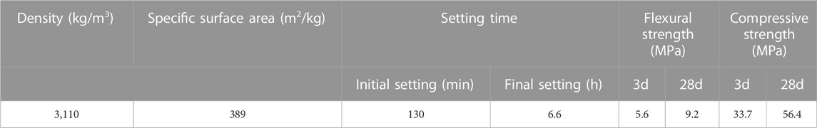
TABLE 1. Physical properties of P.O42.5 ordinary Portland cement.
Three kinds of aggregates are selected, which are 5–10 mm, 10–15 mm, and 15–20 mm. The performance indexes of the aggregates are shown in Table 2. The shape and appearance of the aggregates are shown in Figure 1.
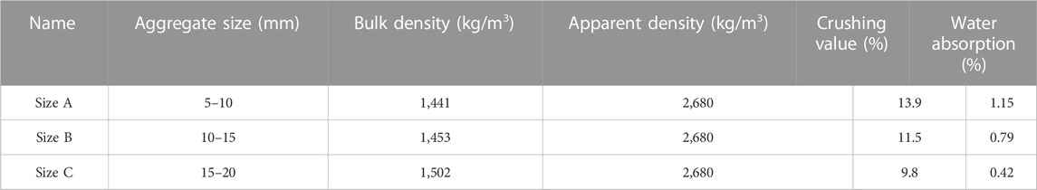
TABLE 2. Physical properties of natural coarse aggregate.
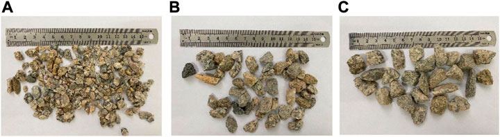
FIGURE 1. Natural coarse aggregate with different particle sizes: (A) 5∼10 mm; (B) 10∼15 mm; (C) 15∼20 mm.
2.2 Sediments
In the actual seepage process of pervious pavements, the clogging substance of different particle sizes in rainwater will reduce the performance of pervious pavements; so, the clogging simulation should be as close as possible to the clogging process in real life. The clogging material of the PC pavement was collected, as shown in Figure 2.
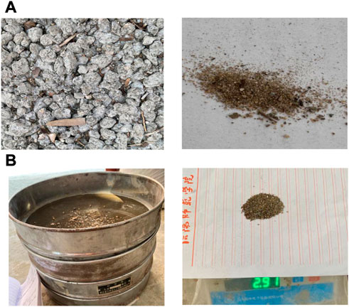
FIGURE 2. Collection and screening of clogging materials: (A) collection of clogging materials; (B) screened clogging materials.
In this study, in order to better understand the range of particle size and clogging depth of clogging material, colored sand with different particle sizes is used as clogging material, as shown in Figure 3. The composition content of clogging material in each particle size range is shown in Table 3.
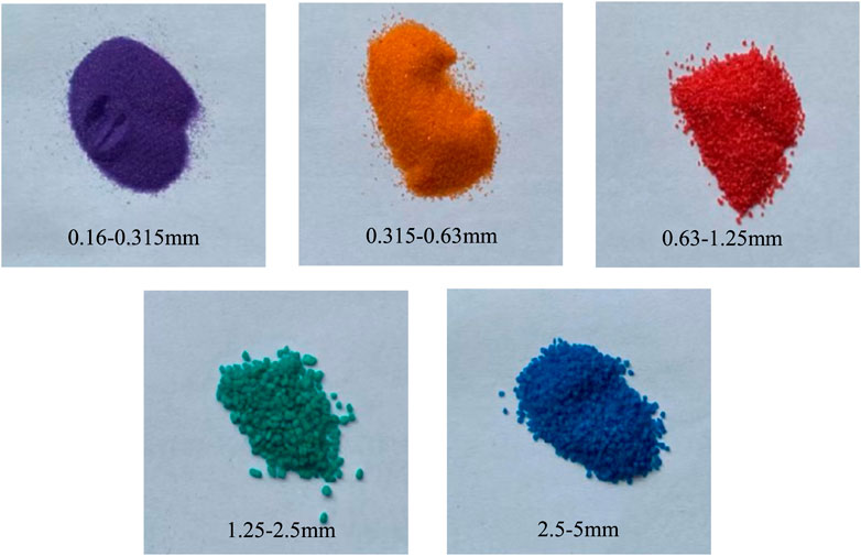
FIGURE 3. Colored sand with different particle sizes.
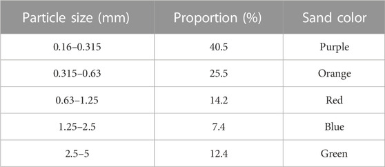
TABLE 3. Colored sand with different particle sizes.
The colored sand is divided into fine sand, coarse sand, and full-grade sand using the screening method, and the particle size ranges are 0.15–0.6 mm, 0.6–4.75 mm, and 0.15–4.75 mm, respectively.
2.3 Pervious concrete production and optimization
2.3.1 Pervious concrete production
The mixing method of this experiment is the cement paste wrapping method. First, the cement is poured into the mixer, and 1/2 the total quantity of water is added and stirred for 1 min to moisten the cement. At this point, coarse aggregate and cement paste may be well combined. Then, the aggregate is added and stirred for the 1 min. The aggregate is fully mixed with cement. Finally, the remaining water is poured and stirred for 2 min to get the PC mixture. In this experiment, there are nine specimens in each group, and the mold size of the specimens is 100 mm × 100 mm × 100 mm.
2.3.2 Pervious concrete optimization
The design point and mixed coarse aggregate analysis were carried out in this study using Design-Expert software, as shown in Table 4. The compressive strength and permeability of PC were predicted and optimized using regression equations and the response surface model. The basic mechanical properties and permeability of PC are optimally balanced by optimizing. After optimization, the proportions of the three groups of mixed aggregates are 5–10 mm:15–20 mm = 7:3, 5–10 mm,10–15:15–20 mm = 3:1. Laboratory experiments verify the reliability of the optimization result. The error relative to the result was controlled by 5%, indicating that the prediction of the measured data of the confirmatory test of PC can be realized through the optimization results of the response surface design and has high accuracy. The optimum thickness of wrapped slurry is selected in the experiment, and the design porosity is 20%. Finally, three groups of PC with high compressive strength and good permeability are obtained and used as representative samples for the clogging test. The optimization results are shown in Table 5.
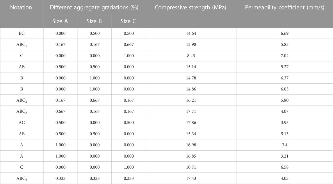
TABLE 4. Simplex centroid design point of aggregate gradation.
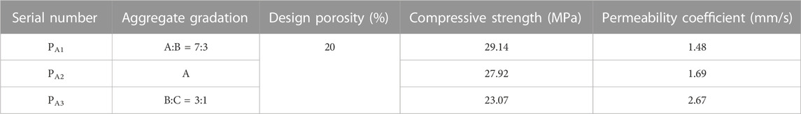
TABLE 5. Optimal performance result of permeable concrete.
2.4 Laboratory clogging experiment
Based on the optimization in Section 2.3.2, three groups of PC specimens with high compressive strength and good permeability were chosen for the anti-clogging test. The simulation test was carried out using the pervious clogging device, as shown in Figure 4. The steps of the laboratory clogging experiment are as follows.
(1) The specimen was sealed with adhesive tape, placed into the self-made pervious clogging device, and the container was lowered into the device. The mixture of clogging particles was collected as shown in Figure 4A.
(2) Around 10 g clogging particles were obtained and spread evenly on the surface of the specimen. The spray intensity of the sprinkler simulating rainfall was kept unchanged and sprayed for 10 min, as shown in Figure 4B.
(3) After the clogging test, the test water was filtered by a 0.16-mm sieve, and then, the collected colored sand was put into a stainless steel tray and placed in the oven. After drying, its mass is a, and it is screened.
(4) The specimen was removed from the device and dried. The colored sand on the surface of the specimen was gently swept. After drying, its mass is b, and it is screened.
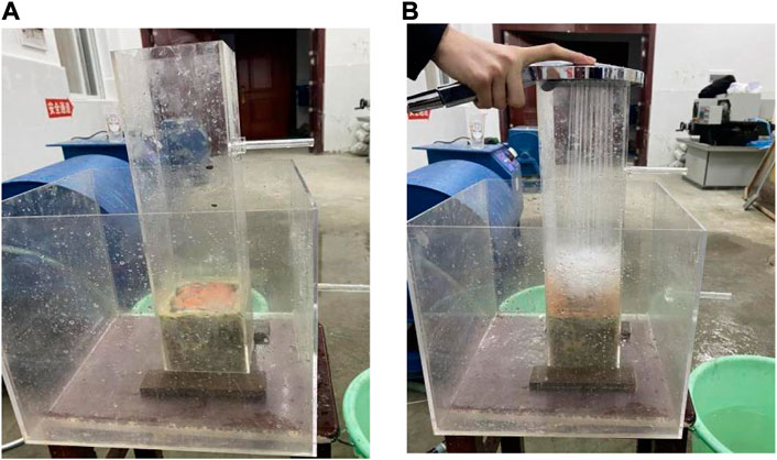
FIGURE 4. Laboratory clogging test: (A) pervious clogging devices; (B) simulated rainfall.
The mass of the colored sand left inside the specimen is 10-a-b. The mass ratio of each particle size range of the internal clogging of the three groups of specimens is shown in Table 6.
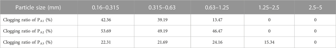
TABLE 6. Mass of each particle size range of the clogging material in the specimen.
3 Test and the simulation design
PFC can be considered a simplified implementation of the DEM. As the skeleton of pervious concrete, the size and shape of aggregate have an important influence on the performance of pervious concrete. The effective performance of the size and shape of the aggregate itself in the numerical simulation determines the effect of the numerical simulation of PC. The CFD module is included in the PFC3D program.
3.1 Discrete element model of pervious concrete
3.1.1 Aggregate scanning
In this study, the particle flow modeling method is adopted. In this experiment, a 3D laser scanner was used to scan the aggregate to obtain the STL file of aggregate outline information, and the corresponding aggregate model was reconstructed by PFC3D5.0 software, as shown in Figure 5.
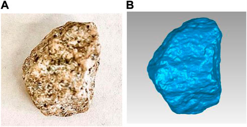
FIGURE 5. True shape of the aggregate and the shape of the aggregate obtained by scanning: (A) true shape of the aggregate; (B) shape of the aggregate obtained by scanning.
3.1.2 Establishment of the aggregate cluster template
In this study, the STL file, which characterizes the outline information of the aggregate, is imported into PFC3D5.0 software to reconstruct the real shape of the aggregate. The specific steps are as follows.
(1) Using the geometry import command built in to create geometry in PFC3D5.0, the STL file of aggregate is imported into software, as shown in Figure 6A.
(2) The imported geometry is the surface outline of the aggregate, while the real aggregate is solid. Therefore, in order to simulate aggregate, it is necessary to fill the geometry with spherical particles, which are discrete elements in PFC3D5.0 software and can be realized by the command of a clump template created in PFC3D5.0. The geometry created in step (1) is imported into PFC5.0 through the keyword geometry, and the particles are automatically filled into the geometry to create an aggregate cluster template, as shown in Figure 6B.
(3) The average aggregate volume was measured by the net basket method after weighing 100 g of each of the three kinds of aggregates. According to the mass ratio of mixed particle size aggregates, the volume fraction of each particle size in three 100 mm × 100 mm × 100 mm samples was calculated, as shown in Table 7. In the discrete element program, each particle’s aggregate size and volume are input, and the samples with different aggregate size ratios are generated according to the aggregate cluster template.
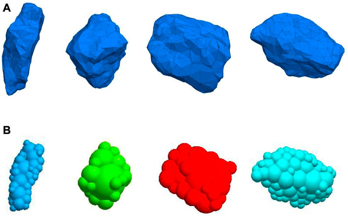
FIGURE 6. Product aggregates of different shapes: (A) real aggregate model; (B) aggregate cluster template.
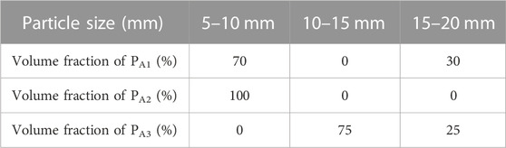
TABLE 7. Volume fraction of each particle size in the sample.
3.1.3 Modeling of pervious concrete specimen
The STL file of the outer profile of the aggregate was introduced into PFC3D5.0 to establish the cluster template to characterize the aggregate. Based on the different particle sizes and porosity of the specimen in the test, the compaction process of permeable concrete was simulated, and the cube specimen of 100 mm × 100 mm × 100 mm was obtained. The specific steps are as follows.
(1) A compression mold is generated. Because of the irregular shape of the aggregate unit, the number of coarse aggregates with a fixed volume in the fixed-volume mold must be less than the ratio of the two volumes; so the volume of the virtual mold is enlarged. After repeated experiments, the mold volume is three times the sample volume, and a cuboid box of 100 mm × 100 mm × 300 mm is generated by using the wall generate command, as shown in Figure 7A
(2) Coarse aggregate is added. Using the clump distribute command, according to the volume fraction of the particle size in different samples in Table 7, a certain number of aggregate models are generated in the box, as shown in Figure 7B
(3) The specimen is compressed. After the aggregate model is generated in the cuboid box, the direction, speed, and time are applied to the upper wall through the servo mechanism. When the mold height reaches 100 mm, the loading is stopped, and the cube test block model of 100 mm × 100 mm × 100 mm is obtained, as shown in Figure 7C.
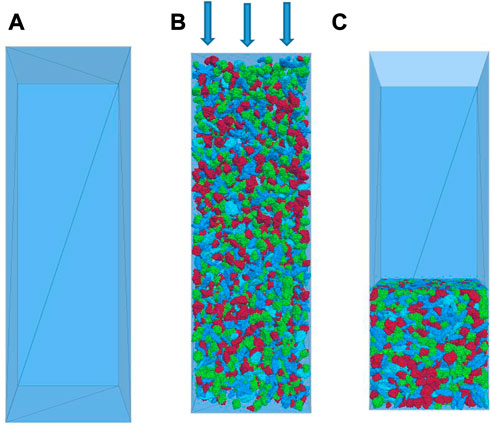
FIGURE 7. Process of model compression: (A) generated compression mold and (B) coarse aggregate filled; (C) compression model.
The contact model used in this study mainly involves the linear stiffness model, and the linear stiffness contact parameters of the aggregate model are shown in Table 8.

TABLE 8. Linear stiffness contact parameters of the aggregate model.
3.2 Modeling of the sediment
In PFC3D, the clogging material is represented by balls of different sizes. The contact between the clogging particles and the clump that makes up the pavement structure is set as a linear stiffness model. The contact parameters are analogous to coarse aggregates. The diameter of clogging particles is 0.16–5 mm. According to the proportion of the particle size of each clogging material in Section 2.2, it is assumed that 2 g clogging material is poured into the virtual specimen. According to the gradation of the clogging material, the median of the two adjacent sieve sizes is taken as the result of the average particle size [32]. The number of clogging materials and contact parameters for each particle size range are shown in Table 9.
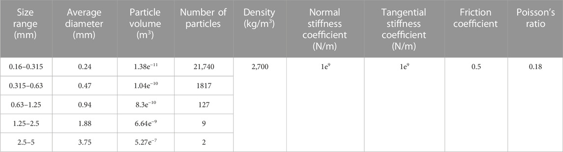
TABLE 9. Number of clogging materials and contact parameters in each particle size range.
3.3 Mathematical equations in the PFC-CFD model
In fact, under the action of rainwater and gravity, clogging particles flow into the interior of PC through the pores of pervious concrete, resulting in the clogging of pervious concrete. However, it is impossible to know the clogging inside the pores. In this study, the clogging simulation test uses the CFD module in PFC3D to visualize the clogging process, and the interaction between particles and fluid is considered.
PFC3D gives the equation of motion of particles:
where
In order to calculate the fluid–particle interaction force, the particle cluster (clump) in PFC is regarded as a single spherical particle (calculating the equivalent radius at the same volume). The fluid–particle interaction force acts on the centroid of the particle cluster (clump) without considering the bending moment. The force exerted by the fluid on the particle (fluid–particle interaction)
Drag force is defined as follows:
where
where
where
where
The physical force applied to the fluid unit is as follows:
where
The physical strength per unit volume of each fluid unit is determined by drag and drag in the PFC3D:
where
The flow with a low Reynolds number in porous media can usually be described by Darcy’s law.
where
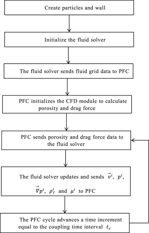
FIGURE 8. Cyclic computation process of two-way coupling of PFC-CFD. The PFC cycle advances at a time increment equal to the coupling time interval
3.4 The setup of the PFC-CFD simulation
The CFD module in PFC can be used to calculate porous media flow under three-dimensional conditions. Generate the boundary of the model wall; the size is 100 mm × 100 mm × 300 mm. A total of 2 g full-grade clogging particles are released on the top of the sample. It is found that the average void velocity of pervious pavements with 20% porosity is 0.015 m/s. At the speed of 0.015 m/s, water flows vertically into the wall from the entrance of the x–y plane located at zonal 0.22 m and flows out from the exit of the x–y plane at zonal 0 m. Except for the entrance and exit, the other wall boundaries are impervious. In the process of two-way coupling, the PC pavement structure composed of clumps always remains at rest, and the clogging particles enter the interior of the PC pavement with the flow of water, as shown in Figure 9.
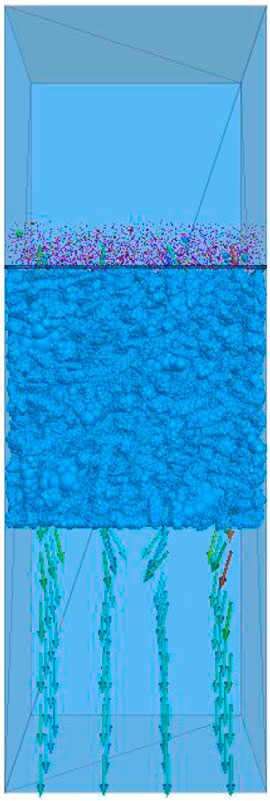
FIGURE 9. Simulated clogging test of permeable pavement under the action of gravity and running water.
The speed of the clump that makes up the pervious pavement is set to 0. The displacement of the clogging particles only changes when there is a collision between the clogged particles and the clump of the pavement. In this study, the time step of the fluid calculation is 2.0 × 10⁻⁴ s. In the actual calculation process, the time step of PFC3D is generally smaller than that of the fluid [32], and the time step of particle calculation is 2.0 × 10⁻⁶ s. The model is preserved every 100,000 time steps until the residual clogging particles in the pavement structure no longer move. The whole process of the two-way coupling calculation was carried out for 6 s.
Based on the optimization of Section 2.3.2, three groups of PC specimens with high compressive strength and good permeability were obtained for the anti-clogging test. In this study, the thickness of the designed pavement was 100 mm, and the pavement structure is divided into five layers along the vertical direction, namely, I layer (0–20 mm), II layer (20–40 mm), III layer (40–60 mm), IV layer (60–80 mm), and V layer (80–100 mm). The simulation test of clogging of three groups of specimens under the action of gravity and running water is shown in Figure 10.
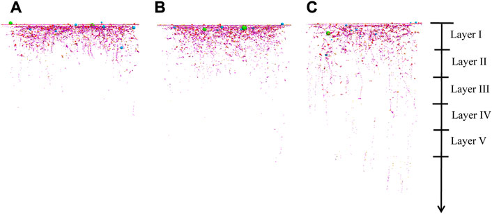
FIGURE 10. Clogging simulation test under the action of gravity and running water. (A) PA1; (B) PA2; (C)PA3.
4 Experimental results and analysis
4.1 Verification of the clogging simulation and test
Based on the same experimental conditions, laboratory and numerical simulation clogging experiments were carried out on three groups of PC specimens. The comparison of the results is shown in Figure 11. Due to the different masses of clogging material between the laboratory clogging test and numerical simulation clogging test, there will be some errors in the results, but the error between the two results is less than 5%. It is proved that the PFC-CFD module in PFC3D can accurately simulate the clogging of PC specimens.
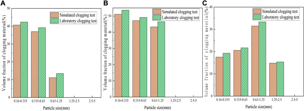
FIGURE 11. Comparison of clogging experiment results between laboratory and numerical simulation. (A) PA1; (B) PA2; (C) PA3.
4.2 Clogging state in the pervious pavement
As shown in Figure 12, there are three states of deposition of clogging materials on the surface of pervious concrete. Figure 12A shows the clogging of the large particle size clogging material. As shown in Figure 13A, the diameter of the clogging material is larger than the size of the pores. The pores of the PC pavement are directly clogged by the clogging material, resulting in a sudden clogging of the pavement. Figure 12B shows the clogging material’s clogging with mixed particle size. The clogging substances of mixed particle size are gathered together; the diameter of the clogging material is smaller than the pore size but very close to the pore diameter. At the same time, the clogging material with a small particle size is also deposited around it, which is equivalent to forming a large particle size clogging material. Figure 12C shows the clogging of small particle size clogging material. As shown in Figure 13B, the diameter of the clogging material is smaller than the pore size of the road. A lot of small particle size clogging material is gathered together; small particle size clogging material easily forms an arch when passing through the pore structure [33], leading to clogging.
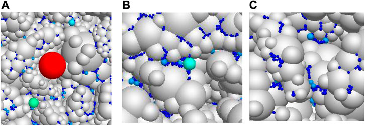
FIGURE 12. Clogging state of clogging materials with different particle sizes in permeable pavement structure: (A) large particle size clogging; (B) mixed particle size clogging; (C) small particle size clogging.
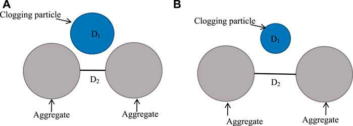
FIGURE 13. Relationship between the diameter of clogging particles and the distance between two aggregates: (A) D1 > D2; (B) D1 < D2.
4.3 Influence of coarse aggregate gradation
The zigzag degree and diameter of pores of PC pavement with different aggregate gradations may be different, and the clogging in the pervious pavement will be different. In this study, clogging simulation experiments were carried out on three groups of PC pavement with different aggregate gradations, and the clogging material is full-grade sand. The variation curve of the volume fraction of clogging particles during the development of road structure clogging over time is shown in Figure 14. The volume fraction of clogging particles in PA1 and PA2 tends to increase and stabilize because there are coarse aggregates with small particle sizes in both PA1 and PA2. The relatively large contact area of small-size aggregate can form relatively small pores, and the clogging material moves slowly down under the action of water flow; so, it is not easy to move out of the pervious pavement structure under the action of water flow. Therefore, the number of clogged particles on the pavement surface will only increase to a certain number but will not decrease. The volume fraction of the clogging substance in PA1 is 8.3% less than that in PA2. PA1 is a kind of PC with discontinuous gradation, and the particle size ratio of coarse aggregate is 5–10 mm:15–20 mm = 7:3 in which small coarse aggregate accounts for the majority. In the PC with mixed particle size aggregate, the contact area between large-size coarse aggregates is small, and it is easy to form large pores. Small-size coarse aggregate is smaller than the pore between the large-size aggregate. The small-size coarse aggregate fills the pores so that the pore size becomes smaller, and it is difficult for clogging material to enter the pores. PA2 is a PC pavement with a single aggregate, and the particle size of coarse aggregate is 5–10 mm. The pores formed are more uniform, and the clogging material enters the pores more easily. Therefore, the volume fraction of the clogging substance in PA2 reaches the maximum first. The volume fraction of clogging particles in PA3 increased rapidly first and then reached a maximum of 56.9% at 1.8 s. It decreased sharply by 31% at 1.2 s and then gradually stabilized. Large-size aggregate concrete with the continuous gradation of PA3 and coarse aggregate particle size ratio is 10–15 mm:15–20 mm = 3:1. Large aggregate size forms a small zigzag degree of pore, and the particle size of secondary aggregate is larger than that between superior aggregates; so, it is impossible to fill the pores and form large pores. Some of the clogging particles migrate out of PA3 under the action of water flow.
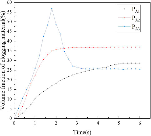
FIGURE 14. Clogging development of different aggregate gradation.
The aggregate gradation in PA1 is a discontinuous gradation; the small-size aggregate fills the pores produced by the large-size aggregate, the large pores are separated by the small-size aggregates to form a smaller pore structure, and the zigzag degree of the pores increases. PA2 is a coarse aggregate with a small particle size and single gradation, so it can form a uniform pore structure with smaller pores but smaller zigzag degree. PA3 is composed of coarse aggregate with large particle sizes and continuous gradation. The diameter of pores formed in permeable pavement structures is larger, and the zigzag degree is small. Therefore, the greater the zigzag degree in the pervious pavement structure, the slower the clogging development, the smaller the pores, and the more clogging materials can block the outside. When aggregate gradation in the pervious pavement is different, the time when the volume fraction of clogging material reaches the maximum is also different. The time when the volume fraction of clogging material in three kinds of pervious pavement reaches the maximum is PA1 > PA2 > PA3, which is related to the zigzag degree and diameter of pores in the pervious pavement. After the clogging material in the pervious pavement tends to stabilize, the volume fraction of the clogging material is 28.8%, 36.9%, and 25.5%, respectively. The results show that the smaller the particle size of coarse aggregate in the pervious pavement is, the easier it is to be clogged.
Figures 15A,B,C show the distribution of clogging substances at different pavement depths of PA1, PA2, and PA3, respectively. By comparing the distribution of clogging particles in three kinds of pervious pavement, there are clogging particles in each layer of PA3 and clogging particles in the first three layers of PA2, but only in the first and second layers of PA1. The volume fraction of clogging particles in the first layer of PA2 is larger than that in the first layer of PA3 because the aggregate size of PA2 is smaller than that of PA3. PA2 can block the entry of clogging particles with large particle sizes, and clogging particles with small particle sizes accumulate in the pavement. Due to the large pore size in PA3, most of the clogging particles can migrate smoothly to the next layer under the action of water flow, and some of the clogging particles pass directly through each layer of the pavement structure. PA1 is a kind of PC with discontinuous gradation, forming the smallest pore diameter and improving the barrier effect. After the occurrence of clogging, the volume proportion of clogging material of PA1, PA2, and PA3 is 28.6%, 36.9%, and 25.5%, respectively, and the anti-clogging performance of PA1 and PA3 is better.
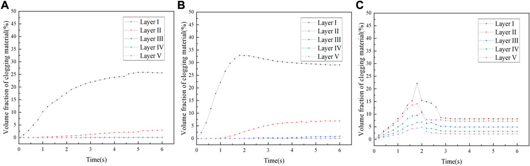
FIGURE 15. Distribution of clogging substances at different pervious pavement depths. (A) PA1; (B) PA2; (C) PA3.
4.4 Influence of clogging material gradation
The three states of clogging material in pervious pavements introduced in Section 4.2 show that the grade of clogging has a certain influence on the clogging development of PC pavement. Different clogging material gradations have different effects on the clogging of pervious pavement. Figures 16A,B,C show the clogging distribution of different gradations of clogging substances in PA1, PA2, and PA3, respectively. The particle size range of fine sand is 0.16–0.63 mm, that of coarse sand is 0.63 mm–5 mm, and that of full-grade is 0.16–5 mm. The results show that the volume fraction of clogging material in PA1 and PA2 has the same trend. PA1 and PA2 are more likely to be clogged by fine sand. Because the pores of these two kinds of pavement are small, they cannot migrate out of the pavement structure under the action of water flow. Fine sand accumulates in the pervious pavement over time, causing serious clogging. When the fine sand is the clogging material, the volume fraction of the clogged material in PA1 and PA2 is larger than that in full-grade sand. Because full-grade sand contains sand with larger particle sizes, the larger sized sand particles are clogged in the pores of the pavement surface layer. They cannot enter the pervious pavement, so part of the smaller-sized sand cannot enter the pore. Therefore, when the full-grade sand is used as the clogging material, the volume fraction of the clogging material decreases by 7.4% and 13.4%, respectively, and the clogging effect of fine sand on PA2 is greater than that of PA1.
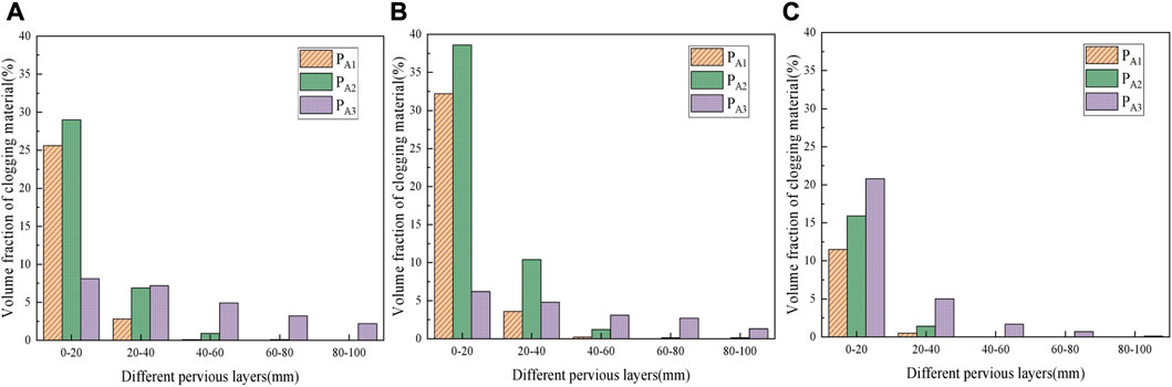
FIGURE 16. Distribution of clogging substances with different gradation in each layer: (A) full-grade sand; (B) find sand; (C) coarse sand.
When the coarse sand is the clogging material, the volume fraction of the clogging material in PA1 and PA2 is the lowest of the three clogging conditions, which are 11.97% and 17.3%, respectively. Most of the particles in coarse sand are larger than the pores of PA1 and PA2, so it is clogged in the surface layer of the pervious pavement and rarely enters the interior and distributes in the first pavement layer. The change of the volume fraction of clogging substance in PA3 is opposite to that of PA1 and PA2. When the clogging material is coarse sand, the volume fraction of clogging material in PA3 is a maximum of 28.45%. The pores formed by PA3 are relatively large, and some large clogging materials can enter its interior to cause clogging. However, when the clogging material is full-grade sand and fine sand, the sand with a smaller particle size is more likely to migrate out of the pervious pavement structure and is less likely to cause clogging. When the full-grade sand is the clogging material, the small particle size and the large particle size aggregates enter the PA3 together, and the small particle size aggregates migrate out of the pervious pavement structure. As a result, when full-grade sand is the clogging material, the volume fraction of the clogging material increases by 7.41%.
As shown in Figure 16A, the clogging substances of the three pervious pavements are full-grade sand. The clogging substances in PA1 are distributed in the first and second layers and can reach a depth of 40 mm. The clogging substances in PA2 are distributed within 60 mm, and the volume fraction of the clogging material in each layer is larger than that in PA1. The clogging substances in PA3 can migrate out of the pervious pavement structure. The distribution of clogging substances in Figure 16B is roughly the same as that of full-grade sand. Figure 16C shows that coarse sand is distributed within 80 mm of PA3. Among the three pervious pavements, coarse sand cannot migrate out of the pervious pavement structure under the action of water flow but is clogged inside it. Among the gradations of the three clogging substances, only coarse sand cannot migrate out of the PA3 structural layer under the action of water flow, which significantly impacts the anti-clogging performance of PA3.
5 Conclusion
The clogging simulation experiments of different pervious pavements are carried out using the two-way coupling method of PFC-CFD. Three clogging states of pervious pavements are obtained, and the effects of coarse aggregate gradation and clogging material gradation on the anti-clogging ability of pervious pavements are analyzed. The conclusions are as follows:
(1) The three states of the deposition of clogging material on the surface of PC are the clogging by large particle size clogging material, the clogging by mixed particle size clogging material, and the clogging by small particle size clogging material. It shows that the gradation of clogging material has a certain influence on the clogging development of PC pavement.
(2) When the aggregate gradation in the pervious pavement is different, the time when the volume fraction of clogged material reaches the maximum is also different. The time when the clogging material in the three kinds of pervious pavement reaches the maximum is PA1 > PA2 > PA3, which is related to the zigzag degree and diameter of pores. After the clogging material in the pervious pavement tends to stabilize, the volume fraction of the clogging material is 28.8%, 36.9%, and 25.5%, respectively, indicating that the smaller the particle size of the coarse aggregate in the pervious pavement is, the more likely it is to be clogged.
(3) Different clogging material gradations have different effects on the clogging of pervious pavement. Therefore, selecting the mix ratio of pervious pavement based on the particle size range of clogging materials in a certain area is necessary for preparing pervious pavement with anti-clogging performance.
(4) The results of this experiment show that PA1 has the highest compressive strength and has a strong barrier effect on full-grade sand and coarse sand. The compressive strength of PA2 is slightly lower than that of PA1, but the anti-clogging ability is the worst. The lowest compressive strength of PA3 is 23.07 MPa, and the clogging material is full-grade sand and fine sand, showing good anti-clogging performance. According to the aforementioned research results, researchers can select different mix ratios of anti-clogging PC according to different areas of use. The law obtained from the experiment can provide a reference for the further study of the design of double-layer pervious pavement structures.
Data availability statement
The original contributions presented in the study are included in the article/Supplementary Materials, further inquiries can be directed to the corresponding author.
Author contributions
QX: supervision, writing—review and editing, conceptualization, and resources; YX: writing—original draft, data curation, and formal analysis; GZ: investigation, validation, and visualization; XL: resources, investigation, and validation; JZ: resources and investigation. All authors contributed to the article and approved the submitted version.
Funding
This research was sponsored by the Training Scheme for Young Backbone Teachers in Colleges and Universities in Henan Province, no. 2019-163; the Excellent Teaching Case Project of Professional Degree Postgraduates in Henan Province (2022-115); the Scientific Research Foundation of Graduate School of Xinyang Normal University (2021KYJJ73); Special Projects of Key R & D and Promotion in Xinyang City (20220055); and Key Scientific and Technological Projects in Henan Province (232102320196).
Conflict of interest
The authors declare that the research was conducted in the absence of any commercial or financial relationships that could be construed as a potential conflict of interest.
Publisher’s note
All claims expressed in this article are solely those of the authors and do not necessarily represent those of their affiliated organizations, or those of the publisher, the editors, and the reviewers. Any product that may be evaluated in this article, or claim that may be made by its manufacturer, is not guaranteed or endorsed by the publisher.
References
1. Kia A, Wong HS, Cheeseman CR. Clogging in permeable concrete: A review. J Environ Manage (2017) 193:221–33. doi:10.1016/j.jenvman.2017.02.018
2. Chen LM, Chen JW, Lecher T, Chen TH, Davidson P. Assessment of clogging of permeable pavements by measuring change in permeability. Sci Total Environ (2020) 749:141352. doi:10.1016/j.scitotenv.2020.141352
3. Afonso ML, Fael CS, Dinis-Almeida M. Influence of clogging on the hydrologic performance of a double layer porous asphalt. Int J Pavement Eng (2020) 21(6):736–45. doi:10.1080/10298436.2018.1508843
4. Hatanaka S, Kamalova Z, Harada M. Construction of a nonlinear permeability model of pervious concrete and drainage simulation of heavy rain in a residential area. Results Mater (2019) 3(9):100033. doi:10.1016/j.rinma.2019.100033
5. Debnath B, Sarkar PP. Clogging in pervious concrete pavement made with non-conventional aggregates: Performance evaluation and rehabilitation technique. Arabian J Sci Eng (2021) 46(11):10381–96. doi:10.1007/s13369-021-05380-6
6. Hung VV, Seo SY, Kim HW, Lee GC. Permeability and strength of pervious concrete according to aggregate size and blocking material. Sustain (2021) 13(1):426–13. doi:10.3390/su13010426
7. Brunetti G, Šimůnek J, Piro P. A comprehensive numerical analysis of the hydraulic behavior of a permeable pavement. J Hydrol (2016) 540:1146–61. doi:10.1016/j.jhydrol.2016.07.030
8. Zhang J, She R, Dai Z, Ming R, Ma G, Cui X, et al. Experimental simulation study on pore clogging mechanism of porous pavement. Constr Build Mater (2018) 187:803–18. doi:10.1016/j.conbuildmat.2018.07.199
9. Sandoval GFB, Galobardes I, Campos A, Toralles BM, 29. January (2020). p. 101203. doi:10.1016/j.jobe.2020.101203Assessing the phenomenon of clogging of pervious concrete (Pc): Experimental test and model propositionJ Build Eng
10. Coughlin JP, Campbell CD, Mays DC. Infiltration and clogging by sand and clay in a pervious concrete pavement system. J Hydrol Eng (2012) 17(1):68–73. doi:10.1061/(asce)he.1943-5584.0000424
11. Lee JW, Yang E, Jang J, Yun TS. Effect of clogging and cleaning on the permeability of pervious block pavements. Int J Pavement Eng (2022) 23(9):3147–56. doi:10.1080/10298436.2021.1884861
12. Kayhanian M, Anderson D, Harvey JT, Jones D, Muhunthan B. Permeability measurement and scan imaging to assess clogging of pervious concrete pavements in parking lots. J Environ Manage (2012) 95(1):114–23. doi:10.1016/j.jenvman.2011.09.021
13. Nan X, Wang Z, Hou J, Tong Y, Li B. Clogging mechanism of pervious concrete: From experiments to CFD-DEM simulations. Constr Build Mater (2021) 270:121422. doi:10.1016/j.conbuildmat.2020.121422
14. Yang Q, Beecham S, Liu J, Pezzaniti D (2019). The influence of rainfall intensity and duration on sediment pathways and subsequent clogging in permeable pavements. J Environ Manage 246, 730–6. doi:10.1016/j.jenvman.2019.05.151
15. Brugin M, Marchioni M, Becciu G, Giustozzi F, Toraldo E, Andrés-Valeri VC. Clogging potential evaluation of porous mixture surfaces used in permeable pavement systems. Eur J Environ Civ Eng (2020) 24(5):620–30. doi:10.1080/19648189.2017.1411834
16. Cui X, Zhang J, Huang D, Tang W, Wang L, Hou F. Experimental simulation of rapid clogging process of pervious concrete pavement caused by storm water runoff. Int J Pavement Eng (2019) 20(1):24–32. doi:10.1080/10298436.2016.1246889
17. Zhang J, Cui X, Li L, Huang D. Sediment transport and pore clogging of a porous pavement under surface runoff. Road Mater Pavement Des (2017) 18:240–8. doi:10.1080/14680629.2017.1329878
18. Sandoval GFB, Galobardes I, De Moura AC, Toralles BM. Hydraulic behavior variation of pervious concrete due to clogging. Case Stud Constr Mater (2020) 13:e00354. doi:10.1016/j.cscm.2020.e00354
19. Huang J, Zhang Y, Sun Y, Ren J, Zhao Z, Zhang J. Evaluation of pore size distribution and permeability reduction behavior in pervious concrete. Constr Build Mater (2021) 290:123228. doi:10.1016/j.conbuildmat.2021.123228
20. Singh A, Sampath PV, Biligiri KP. A review of sustainable pervious concrete systems: Emphasis on clogging, material characterization, and environmental aspects. Constr Build Mater (2020) 261:120491. doi:10.1016/j.conbuildmat.2020.120491
21. Hu N, Zhang J, Xia S, Han R, Dai Z, She R, et al. A field performance evaluation of the periodic maintenance for pervious concrete pavement. J Clean Prod (2020) 263:121463. doi:10.1016/j.jclepro.2020.121463
22. Sandoval GFB, de Moura AC, Jussiani EI, Andrello AC, Toralles BM. Proposal of maintenance methodology for pervious concrete (PC) after the phenomenon of clogging. Constr Build Mater (2020) 248:118672. doi:10.1016/j.conbuildmat.2020.118672
23. Kia A, Wong HS, Cheeseman CR. High-strength clogging resistant permeable pavement. Int J Pavement Eng (2021) 22(3):271–82. doi:10.1080/10298436.2019.1600693
24. Barišić I, Grubeša IN, Dokšanović T, Zvonarić M. Influence of clogging and unbound base layer properties on pervious concrete drainage characteristics. Materials (Basel) (2020) 13:2455–11. doi:10.3390/MA13112455
25. Elango KS, Revathi V. Infiltration and clogging characteristics of pervious concrete. Asian J Civ Eng (2019) 20(8):1119–27. doi:10.1007/s42107-019-00170-w
26. Garcia A, Aboufoul M, Asamoah F, Jing D. Study the influence of the air void topology on porous asphalt clogging. Constr Build Mater (2019) 227:116791. doi:10.1016/j.conbuildmat.2019.116791
27. Zhou H, Li H, Abdelhady A, Liang X, Wang H, Yang B. Experimental investigation on the effect of pore characteristics on clogging risk of pervious concrete based on CT scanning. Constr Build Mater (2019) 212:130–9. doi:10.1016/j.conbuildmat.2019.03.310
28. Chen L, Wang Z, Peng X, Yang J, Wu P, Lian H. Modeling pressurized fracture propagation with the isogeometric BEM. Geomech Geophys Geo-energy Geo-resources (2021) 7(3):51. doi:10.1007/s40948-021-00248-3
29. Parvan A, Jafari S, Rahnama M, Norouzi apourvari S, Raoof A. Insight into particle retention and clogging in porous media; a pore scale study using lattice Boltzmann method. Adv Water Resour (2020) 138:103530. doi:10.1016/j.advwatres.2020.103530
30. Ma G, Zhang J, Dai Z, She R, Xia S, Hu N (2019). Reply to the Comment on ‘Numerical study on pore clogging mechanism in pervious pavements. J Hydrol 578, 124050. doi:10.1016/j.jhydrol.2019.124050
31. Xu J, Kong C, Xu T. Effects of deposition states and distribution regularity of clogging substances on pore clogging behaviors of double-layer drainage asphalt pavement. Constr Build Mater (2021) 314:125701. doi:10.1016/j.conbuildmat.2021.125701
32. Hu J, Ma T, Ma K, 595. January (2021). p. 126028. doi:10.1016/j.jhydrol.2021.126028DEM-CFD simulation on clogging and degradation of air voids in double-layer porous asphalt pavement under rainfallJ Hydrol
33. Remond S. DEM simulation of small particles clogging in the packing of large beads. Phys A Stat Mech Its Appl (2010) 389(21):4485–96. doi:10.1016/j.physa.2010.06.033
34. Nan X, Zhang M, Liu Y, Wang J, Wang L, Jing L. Flow field analysis of micro particles passing through pervious concrete. IOP Conf Ser Mater Sci Eng (2019) 493(1):012006. doi:10.1088/1757-899X/493/1/012006
35. Zhang J, Xia S, Hu N, Hao W, Han R, Meng B, et al. Optimization of anti-clogging pervious pavement structure based on numerical evaluation. Constr Build Mater (2021) 275:122186. doi:10.1016/j.conbuildmat.2020.122186
36. Zhang J, Ma G, Dai Z, Ming R, Cui X, She R. Numerical study on pore clogging mechanism in pervious pavements. J Hydrol (2018) 565(5):589–98. doi:10.1016/j.jhydrol.2018.08.072
37. Zhao W, Chen L, Chen H, Marburg S. Topology optimization of exterior acoustic-structure interaction systems using the coupled FEM-BEM method. Int J Numer Methods Eng (2019) 119(5):404–31. doi:10.1002/nme.6055
38. Chen L, Zheng C, Chen H. FEM/wideband FMBEM coupling for structural-acoustic design sensitivity analysis. Comput Methods Appl Mech Eng (2014) 276:1–19. doi:10.1016/j.cma.2014.03.016
39. Chen L, Marburg S, Chen H, Zhang H, Gao H. An adjoint operator approach for sensitivity analysis of radiated sound power in fully coupled structural-acoustic systems. J Comput Acoust (2017) 25(1):1750003–24. doi:10.1142/S0218396X17500035
Keywords: pervious concrete, PFC-CFD simulation, different aggregate gradation, clogging material, pore clogging
Citation: Xiao Q, Xia Y, Zhang G, Lin X and Zhao J (2023) Numerical simulation study on pore clogging of pervious concrete pavement based on different aggregate gradation. Front. Phys. 11:1162899. doi: 10.3389/fphy.2023.1162899
Received: 10 February 2023; Accepted: 24 February 2023;
Published: 20 March 2023.
Edited by:
Leilei Chen, Huanghuai University, ChinaReviewed by:
Kunming Li, China Three Gorges University, ChinaCheng Ruhui, Xi’an Jiaotong University, China
Copyright © 2023 Xiao, Xia, Zhang, Lin and Zhao. This is an open-access article distributed under the terms of the Creative Commons Attribution License (CC BY). The use, distribution or reproduction in other forums is permitted, provided the original author(s) and the copyright owner(s) are credited and that the original publication in this journal is cited, in accordance with accepted academic practice. No use, distribution or reproduction is permitted which does not comply with these terms.
*Correspondence: Qidan Xiao, eGlhb3FpZGFuMjUzQDE2My5jb20=