 Yamin Zheng
 Yongchen Zhuang
 Shibing Lin
 Deen Wang
 Yifan Zhang
 Lei Huang
- 1Key Laboratory of Photonic Control Technology (Tsinghua University), Ministry of Education, Beijing, China
- 2State Key Laboratory of Precision Measurement Technology and Instruments, Department of Precision Instrument, Tsinghua University, Beijing, China
Deformable mirrors (DMs) are widely used in high-power laser systems to improve the output beam quality. However, under high-power laser irradiation, the heat accumulates on the DM mirror surface and results in high-power laser induced distortions (LID), which will degrade the wavefront correction performance of the DM. In order to suppress the negative impact of the LID on the DM’s performance, we introduce the dual magnetic connection DM (DDM), in which the mirror and the base are connected by two-layer magnets. Configuration of the DDM is presented. The simulation is established to analyze the LID characteristics as well as the wavefront correction performance of the DDM. An experiment is established to investigate the LID of the DDM in practical conditions. Simulation and experiment results indicate that under high-power laser irradiation, the DDM could effectively suppress the LID and maintain good wavefront correction capability.
1 Introduction
Adaptive optics (AO) technology is widely used in atmospheric optics [1–4], biomedical imaging [5–7], and vision science research [8–10] to help obtain high-quality images, as well as in inertial confinement fusion facilities [11–13] and laser systems [14–19] to improve beam quality. A common AO control system includes a wavefront sensor, a wavefront aberration corrector and a wavefront controller. In the AO control of high-power laser systems, deformable mirrors (DMs) are commonly used as the corrector to correct wavefront aberration due to its advances in high laser-induced damage threshold and real-time correction with short response time and high dynamic range [15, 16]. Generally, a newly manufactured DM has a good surface shape without large distortions to ensure that it can correct wavefront aberrations well. Nevertheless, previous studies have found that the wavefront correction performance of a DM is affected by its thermal condition. When the thermal condition of the DM changes, surface distortions appear on the mirror, thus degrading the correction capability of the DM [20–30]. For a DM working in a laser system, there are two common situations that can cause the thermal condition of the DM to change. In the first case, the working temperature of the DM is different from the design temperature, which leads to the temperature-induced distortion (TID) [20–23]. In the second case, the heat gradually accumulates on the mirror surface under high-power laser irradiation, which results in the laser-induced distortion (LID) [24–29]. It is worth noting that the TID occurs when both the mirror and the base reach thermal steady state under ambient temperature changes, while the LID occurs when the mirror is heated individually and there is a temperature difference between the base and the mirror. Typically, the TID under a certain temperature variance does not change over time and is dependent on the linear expansion coefficient difference between the base and the mirror. While the LID varies with the duration of laser irradiation and is mainly dependent on the heat accumulation of the mirror.
Some research has been done to investigate how to suppress the TID of the DM [21–23]. From the study about TID it could be seen that under temperature variation, the DM’s surface shape appears not only low-order but also high-order distortions with the high-order ones particularly dependent on the configuration of the DM [21]. To suppress the TID, they suggested that the thermal expansion coefficient of the base material be similar to that of the mirror material. However, in normal conditions, it is difficult to maintain the mechanical performance of the DM and use materials with similar linear expansion coefficients for the mirror and the base at the same time. A temperature compensation module was introduced to actively compensate the TID [22]. The study systematically analyzed the TID based on thermal stress characteristics and showed that the TID, which could not be self-corrected by the DM, mainly came from the tilt of the DM actuators due to temperature change. By introducing a temperature compensation module behind the stainless-steel base as well as using a hybrid control algorithm, the TID could be well compensated. Non-etheless, this method increases the complexity of the DM control component and is not effective on the LID. A hybrid connection structure DM (HDM) was proposed to suppress high-frequency TID, adopting both magnetic connection structure and conventional adhesive connection structure in the DM [23]. Nevertheless, the conventional adhesive connection used on the four corner actuators caused concentrated stress and deformation in the mirror, which limited the effective area of the HDM and degraded the wavefront correction performance.
Some research has been done to investigate how to suppress the LID of the DM [27–30]. The influence of the LID on the phase distortion and Strehl ratio in the far-field was calculated, and it was shown that a mirror’s LID was related to thermal characters of the mirror material [27]. In the meantime, utilizing material which has high specific heat and low thermal expansion coefficient would help suppress the LID. Water cooling channels were embedded inside the Silicon carbide mirror of a DM to actively dissipate the heat accumulated on the mirror without hindrance to the optical stability of the system, thus suppressing the LID [28]. In another research, a Silicon mirror DM also used water cooling to avoid LID under high-power laser [29]. Moreover, a stacked-actuator DM with water-cooling system was developed to compensate the LID brought by high-power laser [30]. Although water cooling is an effective way to eliminate heat from the mirror, adding a water-cooling module directly to the mirror will increase the difficulty of DM packaging and introduce the risk of water leakage damaging the DM.
In this paper, a dual magnetic connection DM (DDM) is proposed to suppress the LID under high-power laser applications. In Section 2, the LID characteristics of the DDM, the ADM, and the traditional adhesive connection DM (ADM) whose mirror and base are set to the same material are investigated in simulation using the finite element method. The results indicate that under the same high-power laser irradiation, the LID of the HDM and the ADM are larger and more difficult to be well self-corrected than that of the DDM. The wavefront correction performance of the DDM is analyzed by compensating Zernike mode aberrations in simulation. In Section 3, a lab-manufactured DDM is presented, and an experiment is established to investigate the LID of the DDM under practical conditions. The experiment results correspond well with the simulation results that the LID of the DDM is suppressed and could be well self-corrected.
2 Simulation
2.1 Configuration of the DDM
In order to compare the surface distortion as well as the wavefront correction performance of the DDM, ADM and HDM under high-power laser irradiation, models of the three DMs are established. Note that the ADM and the HDM both are effective ways to suppress the TID on the mirror surface when the working temperature is different from the design temperature. Non-etheless, the TID happens under the thermal steady state which the DM takes a long time to reach, while the LID happens under high-power laser irradiation in a short time. Therefore, it would be helpful to investigate the LID characteristics of the ADM and the HDM through finite element methods and compare the results between the ADM, the HDM and the DDM. The structure of the DDM, the HDM, and the ADM is shown in Figure 1. All three DMs are constructed with a mirror which has posts and a base which has flexure plates, with the corresponding components sharing the same size between different DMs. However, it could be seen from Figure 1 that the structure difference of the DDM, the HDM, and the ADM lies in the way of connection between the mirror and the base. For the DDM shown in Figure 1A, two layers of magnets are used between the mirror and the base, connecting them with magnetic force. The upper layer of magnets connects the mirror posts upwards with adhesive connection, and the lower layer connects the flexure plates with adhesive connection. Then the two layers of magnets connect each other with magnetic connection. For the HDM shown in Figure 1B, the four corner mirror posts are attached to the base using adhesive connection, while the other mirror posts are attached using magnetic connection. Figure 1C shows the structure of the ADM whose all pairs of mirror posts and flexure plates are connected with adhesive connection. To investigate the LID characteristics of the DDM, finite element models are constructed in COMSOL Multiphysics software [31]. Figure 1D shows the actuator location of the DM models. All 49 actuators are distributed in a 7 × 7 square arrangement. The distance between two adjacent rows/columns of actuators is 12 mm, and the distance between the actuators in the outermost row/column and the mirror edge is 6 mm. Furthermore, we investigate the LID of the DDM for different effective area sizes as shown in Figure 1E, which is also applied to the HDM. l is the side length of the effective area. Three area sizes are chosen: 76 mm × 76 mm, 68 mm × 68 mm, and 60 mm × 60 mm. For the areas with the latter two sizes, the outermost 24 actuators are not included.
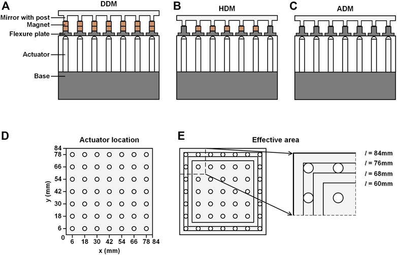
FIGURE 1. Schematic view of the structure of the DM. (A) DDM. (B) HDM. (C) ADM. (D) Actuator location (φ = 5 mm). (E) Effective area sizes of the DDM. l: Side length of the effective area.
Structural and material parameters of the DM are shown in Table 1 and Table 2, respectively. BK7 is used as the mirror material of the three DMs. For the DDM and the HDM, stainless steel is set as the base material and NdFeB magnet is set as the magnet material. For the ADM, all components are made of BK7. The dimensions of corresponding components are the same between the three DMs. The DDM’s overall height is higher than the other two DMs due to the two-layer magnets.
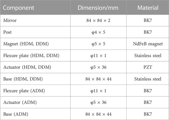
TABLE 1. Structural parameters of the DM models.
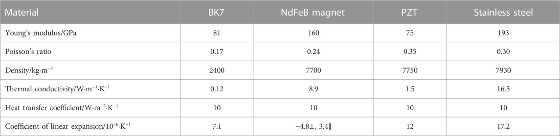
TABLE 2. Material parameters of the DM models.
The finite element models are based on thermal stress analysis. Models of the DDM, the HDM, and the ADM use the same constraint and thermal settings. A fixed constraint is applied on the center point of the base undersurface to prevent the base from moving. The rotation and the z-axis displacement of the undersurface are set to zero. The heat transfer coefficient of every outer surface is set to 10 W∙m−2∙K−1. The initial ambient temperature and DM temperature are set to 20°C, reaching thermal steady state. The initial surface shape of the DM is set to an ideal plane surface. Typically, for a DM used in a high-power laser system, a mirror coating is applied to avoid damage to the mirror and provide high-ratio reflectivity. In the simulation, a heat flux of 1000 W∙m−2 is set on the mirror’s outer surface to simulate the heat absorbed by the mirror after the laser is reflected by the coating. For a mirror coating of 99.9% reflectivity, a heat flux of 1000 W∙m−2 absorbed by the mirror corresponds to a laser power density of 1000 kW∙m−2. The duration of laser irradiation is set to 60 s. After 60 s of laser irradiation and heat absorption, the DM deforms, and LID appears on the mirror surface. Note that the thermal steady state is not reached. Furthermore, to explore the LID under long-time irradiation, LID results after 600 s and 6000 s duration are also calculated.
To investigate the wavefront correction performance of the DMs under high-power laser irradiation, the influence function (IF) is also calculated through the finite element models. With the same stress constraint preset mentioned above, to obtain the response of a certain actuator channel, the contact surface between the flexure plate and the magnet is set to shift up 1 μm along the z-axis. Mirror surface deformations of each actuator channel together form the IF of the DM. After that, the analyses of LID characteristics and wavefront correction performance of the DDM, the HDM, and the ADM are carried out in MATLAB software [32]. Here, we adopt the least squares method as the wavefront correction algorithm in the simulation [33].
2.2 Investigation on the LID of the DDM
The investigation of the LID characteristics and temperature distribution of the DDM are implemented through the finite element model. With two layers of magnets connecting the mirror with the base, the DDM could both suppress the actuator tilt under high-power laser irradiation and maintain structure stability. In the simulation, the DDM is subjected to laser irradiation and heat absorption for 60 s. Before the laser irradiation, the DDM is in thermal steady state with the temperature of 20°C. The temperature distribution of the DDM under 60 s laser irradiation is shown in Figures 2A,B. The deformation of the mirror surface under laser irradiation is recorded as the LID, and the results are shown in Figure 2(C–E).
FIGURE 2. Temperature distribution and LID of the DDM under 60 s laser irradiation. (A) Overall temperature distribution TV. (B) Mirror temperature distribution TS. (C) Initial LID. (D) Self-correction residual. (E) Diagonal cross-section view of the LID.
Figure 2A shows that after 60 s of laser irradiation covering the mirror surface, the temperature distribution of the overall DDM (TV) forms a gradual decrease from top to bottom. The main temperature rise occurs in the mirror, including the faceplate and the posts. The faceplate of the mirror reaches over 30°C, with an over 10°C rise than the initial temperature. The base temperature remains 20°C, indicating that the heat does not reach the base under 60 s duration. It could be seen from Figure 2B that the temperature distribution of the mirror surface (TS) is between 30.1°C and 31.8°C. Compared to other regions of the mirror surface, the regions closer to the mirror posts have lower temperature rise since the heat is transferred downwards.
From Figure 2C it could be seen that there is no concentrated distortion at the corners and no large actuator-corresponding high-frequency distortion on the mirror surface of the DDM. Compared with the LID of the HDM and the ADM mentioned below, the LID of the DDM has smoother deformations. The self-correction residual shown in Figure 2D also shows no large concentrated distortion and large actuator-corresponding distortion. The self-correction residual is obtained by compensating the LID with the IF of the DDM. The diagonal cross-section view of the LID of the DDM is shown in Figure 2E. The peak-to-valley (PV) value of the LID 0.33 μm, and the root-mean-square (RMS) value of the LID is 0.05 μm. The PV value and the RMS value of the self-correction residual are 0.09 μm and 0.01 μm, respectively.
Figure 3 shows the LID of the DDM with different effective area sizes. It could be seen that the LID and the self-correction residuals show no high-frequency distortion, indicating that the DDM has no effective area loss.
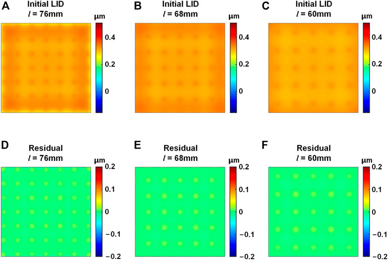
FIGURE 3. LID of the DDM with different effective area sizes. (A–C) Initial LID with the area side length l of 76 mm, 68 mm, and 60 mm, respectively. (D–F) Self-correction residuals with the l of 76 mm, 68 mm, and 60 mm, respectively.
The LID characteristics of the DDM under long-time laser irradiation are also investigated. Temperature distributions of the overall DDM and the mirror surface are shown in Figure 4. It could be seen that the temperature distribution forms are similar with the results shown in Figure 2. The mirror surface temperature TS under 600 s laser irradiation is between 45.6°C and 51.0°C, while TS under 6000 s laser irradiation is between 47.1°C and 52.5°C. For the mirror surface, with the increase of laser irradiation time, the increase of temperature rise tends to be stable. During the laser irradiation, the heat continuously transfers from the mirror to the base, thus the temperature of the base increases. After 600 s laser irradiation and heat transfer, the lowest temperature of the base undersurface reaches 20.2°C, while after 6000 s laser irradiation it reaches 23.0°C. The results indicate that under laser irradiation, the temperature distribution of the overall DM follows a gradient distribution with a decrease from top to bottom.
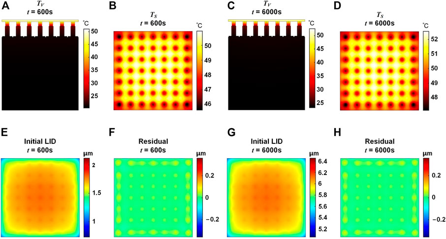
FIGURE 4. Temperature distribution and LID of the DDM under 600 s and 6000 s laser irradiation. (A) Overall temperature distribution TV, t = 600 s. (B) Mirror temperature distribution TS, t = 600 s (C) TV, t = 6000 s (D) TS, t = 6000 s. (E) Initial LID, t = 600 s. (F) Self-correction residual, t = 600 s. (G) Initial LID, t = 6000 s. (H) Self-correction residual, t = 6000 s.
The LID of the DDM under laser irradiation of 600 s and 6000 s are shown in Figure 4(E–H). Under 600 s laser irradiation, the LID of the DDM has the PV value of 0.79 μm and the RMS value of 0.13 μm. After self-correction, the PV value of the residual is 0.12 μm with an 85% reduction, and the RMS value is 0.02 μm with an 85% reduction. Under 6000 s laser irradiation, the PV value and the RMS value of the LID are 0.79 μm and 0.13 μm, respectively. After self-correction, the PV value and the RMS value of the residual are 0.11 μm with an 86% reduction and 0.02 μm with an 85% reduction, respectively. It could be seen that the DDM has good self-correction capability.
The simulation results demonstrate that the DDM could suppress the LID effectively. Table 3 shows the detailed LID simulation results of the DDM and temperature distribution results of the mirror surface under 60 s, 600 s, and 6000 s laser irradiation. ΔTS indicates the difference between the lowest temperature and the highest temperature of TS. The simulation results of the HDM and the ADM are also listed in Table 3, which will be introduced and analyzed in subsequent sections. For the initial LID and residual shown in Table 3, the percentage shown in parentheses after the number indicates the ratio of the PV/RMS value of them to the PV/RMS value of corresponding DDM LID results under the same laser irradiation duration.
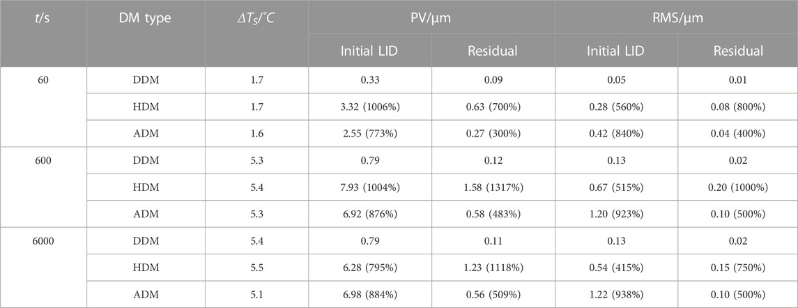
TABLE 3. LID and mirror temperature results of the DDM, the HDM, and the ADM.
2.3 LID characteristics of the HDM and the ADM
The simulation results introduced above show that the DDM could effectively suppress and self-correct the LID under high-power laser irradiation. To further demonstrate the advantage of the DDM structure on LID suppression, investigations on the LID characteristics of the HDM and the ADM are also established through finite element models in simulation.
2.3.1 LID characteristics of the HDM
In the simulation, the HDM has the same stress constraint and thermal condition with the DDM. The HDM adopts adhesive connection to connect the mirror and the base in the four corner actuator channels and adopts magnetic connection in other actuator channels. The temperature distribution and the LID characteristics of the HDM are shown in Figure 5.
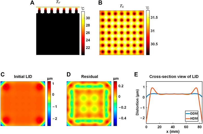
FIGURE 5. Temperature distribution and LID of the HDM under 60 s laser irradiation. (A) Overall temperature distribution TV. (B) Mirror temperature distribution TS. (C) Initial LID. (D) Self-correction residual. (E) Diagonal cross-section view of the LID.
It could be seen from Figure 5 that the temperature distribution of the ADM under 60 s laser irradiation is similar with that of the DDM. For the overall ADM, the temperature decreases from top to bottom. The temperature of the DDM mirror surface varies from 30.1°C to 31.8°C, same as the temperature range of the DDM mirror surface.
The corresponding LID characteristics are shown in Figure 5(C–E). Figure 5C shows the LID of the HDM under 60 s laser irradiation. The PV value of the LID of the HDM under 60 s irradiation is 3.32 μm, 906% larger than that of the DDM. The corresponding RMS value is 0.28 μm, 460% larger than that of the DDM. The PV value and the RMS value of the self-correction residual are 0.63 μm and 0.08 μm, respectively. It could be seen that the surface shape of the mirror surface’s central area is higher than that of the four corners’ areas, showing a convex surface shape for the overall mirror. Deformations on the four corners of the mirror are larger than those on the central area. On each corner, from the center of the mirror out, the surface shape changes sharply from high to low. The sharp surface shape deformation is reflected in the self-correction residual (Figure 5D) and the diagonal cross-section view of the LID (Figure 5E). The blue and red curves are the diagonal cross-section views of the LID of the DDM and the HDM, respectively. The DDM’s curve has the smaller range and the smoother deformation. It could be seen that concentrated distortions appear on the corner area of the HDM. Therefore, to achieve good wavefront correction performance, the effective area of the HDM should be limited.
The initial LID and the self-correction residuals of the HDM with different effective area sizes are shown in Figure 6. It could be seen that for the HDM with the effective area size lengths of 76 mm and 68 mm, the concentrated deformation still appears on the four corners of the mirror and could not be effectively self-corrected. As shown in Figure 6F, for the HDM with the effective area size length of 60 mm, the concentrated deformation could be suppressed. Compared with the full 84 mm × 84 mm mirror surface, the 60 mm × 60 mm effective area is much smaller with a 51% area loss. The concentrated deformation on the four corners of the HDM could not be self-corrected effectively, which limits the effective area and, furthermore, limits possible applications of the HDM.
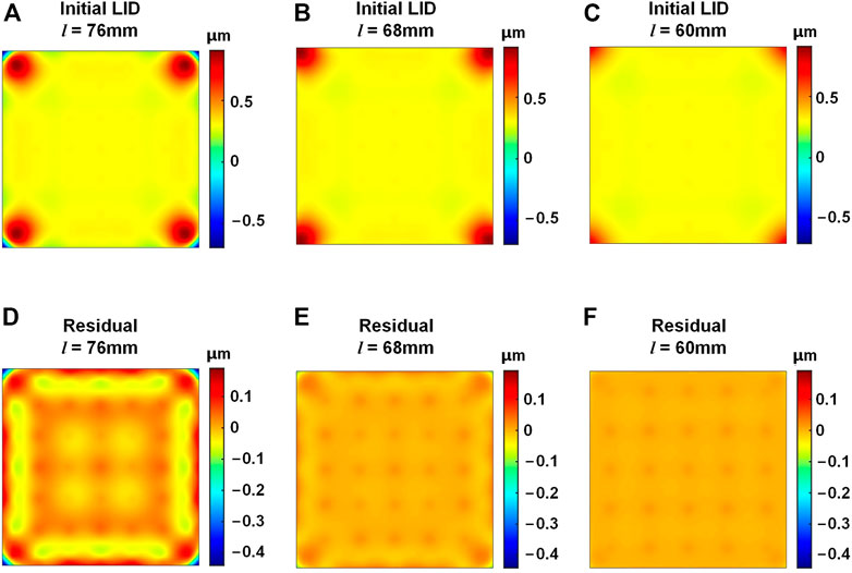
FIGURE 6. LID of the HDM with different effective area sizes. (A–C) Initial LID with the area side length l of 76 mm, 68 mm, and 60 mm, respectively. (D–F) Self-correction residuals with the l of 76 mm, 68 mm, and 60 mm, respectively.
The temperature distribution and the LID characteristics of the HDM under 600 s and 6000 s laser irradiation are also investigated, as shown in Figure 7. It could be seen that the temperature distribution of the HDM is similar to that of the DDM. The temperature distribution TV of the HDM follows a gradient distribution with a decrease from top to bottom, which is different from that in the TID’s condition. In the TID’s condition that the ambient temperature changes, the whole DM ends up at the same temperature. The PV values of the LID of the HDM under 600 s and 6000 s laser irradiation are 7.93 μm and 6.28 μm, respectively. The corresponding RMS values are 0.67 μm and 0.54 μm, respectively. Compared with the LID of the DDM under 600 s and 6000 s laser irradiation, the LID of the HDM has a significant rise in PV and RMS values and also has differences in surface shape structure. In the HDM LID shown in Figure 7, it could be seen that there exist distortions with large deviation gradients in the four corners. According to the analysis of LID under 60 s irradiation, these corner distortions not only lead to the large PV and RMS values of the HDM LID, but also are difficult to be self-corrected by the HDM. For the HDM, to reduce the influence brought by the corner distortions and obtain good self-correction ability, a smaller effective area should be selected. While for the DDM LID shown in Figure 4, the distortions are relatively flat throughout the mirror area and could be effectively self-corrected without sacrificing the effective area. Therefore, the DDM has better self-correction ability than the HDM. The PV values of the self-correction residuals of the HDM LID under 600 s and 6000 s laser irradiation are 1.58 μm and 1.23 μm, respectively, which are 1217% and 1018% larger than those of the DDM. Detailed results are shown in Table 3.

FIGURE 7. Temperature distribution and LID of the HDM under 600 s and 6000 s laser irradiation. (A) Overall temperature distribution TV, t = 600 s. (B) Mirror temperature distribution TS, t = 600 s (C) TV, t = 6000 s (D) TS, t = 6000 s. (E) Initial LID, t = 600 s. (F) Self-correction residual, t = 600 s. (G) Initial LID, t = 6000 s. (H) Self-correction residual, t = 6000 s.
2.3.2 LID characteristics of the ADM
An ADM in which components are made of the same material has poor mechanical properties, compared to a traditional DM. Non-etheless, the ADM could solve the TID problem to the maximum extent since there is no linear expansion coefficient difference. To ideally eliminate the TID, either the ambient temperature change should be avoided, or the linear expansion coefficients of different components should remain the same. To avoid changing the ambient temperature, a temperature controller should be used to adjust the working temperature to be close to the design temperature of the DM, which is difficult to implement. By using the same material to form the DM, there is no need to control the ambient temperature after the ADM is manufactured. Thus, the ADM is an effective way to suppress the TID.
Although the ADM performs well in TID suppression, when it is working under laser irradiation, the LID would appear on the mirror surface due to the heat accumulation of the mirror. The temperature distribution and LID characteristics of the ADM are investigated in finite element models. The ADM has the same stress constraint and thermal condition with the DDM and the HDM. BK7 is taken as the material of the ADM. The adhesive connection is used for each pair of mirror post and base flexure plate of the ADM. After laser irradiation, the temperature distribution of the ADM is similar to that of the HDM and the DDM, and specific data are shown in Table 3.
The LID characteristics of the ADM under laser irradiation are shown in Figure 8. From Figure 8(A–C) it could be seen that there appear actuator-corresponding distortions in the LID of the ADM. Under the condition that the working temperature is different from the design temperature, no TID would appear on the ADM since the linear expansion coefficient of different components remain the same. However, under the condition of laser irradiation, heat accumulates gradually on the mirror and transfers slowly to the base. The mirror and the base have different temperatures, leading to actuator tilt and actuator-corresponding LID. The PV values of the LID under 60 s, 600 s, and 6000 s are 2.55 μm, 6.92 μm and 6.98 μm, respectively, which are 673%, 776%, and 784% larger than the corresponding PV values for the DDM. The RMS values of the LID are 0.42 μm, 1.20 μm, and 1.22 μm, respectively, which are 740%, 823%, and 838% larger than the corresponding RMS values for the DDM. The RMS values of the LID of the ADM are larger than those of the HDM shown in Table 3. While for the self-correction residuals, the RMS values of the self-correction residuals of the ADM are smaller than those of the HDM. The RMS values under 60 s, 600 s, and 6000 s laser irradiation are 0.04 μm, 0.10 μm, and 0.10 μm, respectively. The corresponding PV values are 0.27 μm, 0.58 μm, and 0.56 μm, respectively, which are smaller than the PV values of the HDM’s self-correction residuals. This indicates that under laser irradiation, the actuator-corresponding distortions of the ADM are more evenly distributed than the concentrated distortions of the HDM, and the self-correction results of the ADM are better than the HDM. Non-etheless, there is still high-frequency LID on the ADM mirror surface, and it is difficult to manufacture the ADM while maintain good mechanical properties. Detailed LID simulation results of the ADM and the temperature characteristics of the mirror surface under 60 s, 600 s, and 6000 s laser irradiation are shown in Table 3. The LIDs of the DDM, ADM and HDM under Gaussian-like heat irradiation in different time duration are also calculated in the simulation, and the results are the same as those under uniform heat irradiation that the DDM has suppressed LID and could maintain good wavefront correction capability.
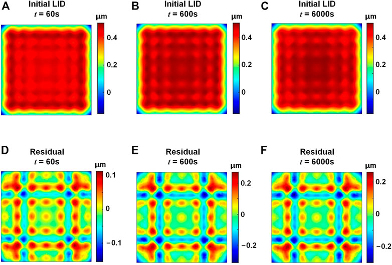
FIGURE 8. LID of the ADM under laser irradiation. (A–C) LID, t = 60 s, 600 s, and 6000 s, respectively. (D–F) Self-correction residuals, t = 60 s, 600 s, and 6000 s, respectively.
2.4 Wavefront correction performance of the DDM
To make comparison of the wavefront correction performance between the DDM and the HDM, Figure 9(A–B) shows the PV as well as the RMS values of the LID and self-correction residuals of the two DMs. It could be seen that the initial LID of the DDM, which has not been corrected, has lower PV and RMS values than the self-correction residual of the HDM, not to mention the self-correction residual of the DDM. This indicates that in terms of suppressing LID, the DDM performs better than the HDM. Figure 9(C–F) show the results of the simulation which is implemented to study the effect of the LID on the wavefront correction performance of the DDM. Third–10th Zernike mode aberrations are taken as the initial distortions that need to be fitted. Furthermore, to investigate the deterioration of correction performance due to the LID, another correction is implemented with the LID corresponding to the HDM and the DDM under 60 s laser irradiation superimposed to each Zernike mode aberration as the initial distortion. PV values of the original Zernike mode aberrations are uniformly set to 3 μm.
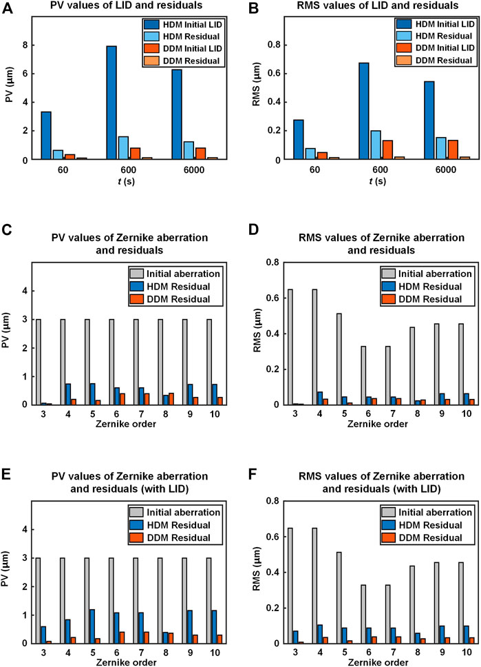
FIGURE 9. Wavefront correction performance of the HDM (blue ones) and the DDM (orange ones). (A) PV and (B) RMS values of LID and self-correction residuals. (C) PV and (D) RMS values of initial aberration and correction residuals of Zernike mode aberrations. (E) PV and (F) RMS values of initial aberration and correction residuals of Zernike mode aberrations superimposed with LID.
Figures 9A,B shows that the PV and RMS values of the correction residuals of the DDM are smaller than those of the HDM. It could also be seen from Figure 9C–F that with the superimposition of the LID, the PV and RMS values of the correction residuals show varying degrees of increase, indicating the negative effect of the LID on the wavefront correction performance of the DM. With the superimposition of the LID, the PV values of the HDM correction residuals have an average rise of 143%, and the RMS values 187%. While the PV values of the DDM correction residuals have an average rise of 15%, and the RMS values 18%. The difference in wavefront correction ability between the DDM and the HDM comes from their different physical and thermophysical mechanisms. When the DM is working under laser irradiation, heat accumulates gradually on the mirror and transfers to the base, resulting in a difference in temperature variation between the mirror and the base, as well as a difference in the thermal expansion scale between them. After that, the different thermal expansion scales cause mirror posts to tilt and further generate local high-frequency distortions on the mirror surface. For the DDM, two layers of magnets are used between the mirror and the base, connecting them with magnetic force. When the mirror post tends to tilt, the magnetic connection structure allows relative displacement between the mirror post and the flexure plate, whereas the adhesive connection structure does not. The HDM and the ADM use adhesive connection structure for the four corner posts and all posts, respectively, resulting in high-frequency distortion in the LID that could not be effectively self-corrected. Therefore, compared with the HDM and the ADM, the DDM has an advantage that the LID could be suppressed and effectively self-corrected, allowing the DDM to have better wavefront correction ability under high-power laser irradiation.
In conclusion, under high-power laser irradiation, the LID generated on the mirror surface of the DM would deteriorate the wavefront correction performance, and the DDM suffers much smaller loss of wavefront correction performance than the HDM.
3 Experiment
The experiment is carried out to measure the LID of a lab-manufactured DDM. Structure of the DDM is shown in Figure 10A. The DDM consists of a mirror with posts, two layers of magnets, base with flexure plates, actuators, and other internal components. No mirror coating is applied to the mirror. The material of the mirror is BK7, the material of the magnet is NdFeB magnet, and the material of the base is stainless steel. The structural parameters of the lab-manufactured DDM are shown in Figure 1.
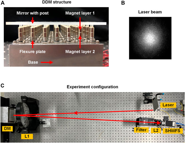
FIGURE 10. Experiment configuration of the lab-manufactured DDM. (A) DDM structure. (B) Intensity distribution of the laser beam. (C) Experiment configuration.
Configuration of the experiment is shown in Figures 10B,C. A fiber laser (lab-assembled, 1064 nm wavelength, 10 W total power) is used as the irradiation source. The laser is generated by the fiber laser, and then it passes through the lens L1 (f = 1050 mm, φ = 200 mm, AR coated with transmission >99.7% at 1064 nm) which is used for light collimation. After that, the laser is reflected by the DM and passes through the L1 in a reversed direction. It should be noted that the back surface of the mirror is made opaque so that most of the heat is absorbed by the mirror. The laser then passes through a filter to decrease the laser power and protect the Shack-Hartmann wavefront sensor (SHWFS). The lens L2 (f = 75 mm, φ = 20 mm) is used to convert the large beam into a smaller beam to fit the detection zone size of the SHWFS. The SHWFS contains a micro-lens array (MLA, 6 mm × 6 mm size, 300 μm sub-aperture interval, 20 × 20 sub-apertures in a square array, f = 8.6 mm) and a charge coupled device (CCD, Basler’s piA1000-48 gm, 1004 × 1004 pixels, 7.4 µm × 7.4 µm pixel size, 7.4 mm × 7.4 mm sensor size).
To measure the LID, the laser is first turned on and the initial wavefront is measured immediately. After that, the light is prevented from entering the filter and the SHWFS until next measurement, to ensure that the thermal distortion of the DDM is accurately measured. Then the wavefront is measured after 300 s, 600 s and 900 s of laser irradiation, respectively. The difference between each measured wavefront and the initial wavefront is calculated as the LID. The heat flux of the laser on the DM is 1000 W/m2. Figure 11 shows the LID of the lab-manufactured DDM under laser irradiation. The initial LID under 300 s irradiation has the PV value of 0.43 µm and the RMS value of 0.08 µm. The PV and the RMS values of the self-correction residual are 0.05 µm and 0.01 µm, respectively. After self-correction, the PV value of the LID is 88% smaller and the RMS value is 87% smaller. The LID under 600 s and 900 s irradiation both have the PV value of 0.43 µm and the RMS value of 0.08 µm, and it could be seen from Figure 11 that the self-correction residuals are effectively self-corrected.
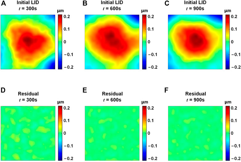
FIGURE 11. LID of the lab-manufactured DDM under laser irradiation. (A–C) LID, t = 300 s, 600 s, and 900 s, respectively. (D–F) Self-correction residuals, t = 300 s, 600 s, and 900 s, respectively.
The wavefront correction performance of the DDM is investigated, using the Zernike mode aberrations as the initial distortions, as shown in Figure 12. The correction residuals of Zernike mode aberrations superimposed with the LID under 300 s laser irradiation are also calculated. It could be seen that the PV and the RMS values of the correction residuals are much smaller than the that of the initial aberrations, showing good wavefront correction performance. Moreover, the average wavefront correction performance loss with the introduction of the LID is 17% in PV value and 9% in RMS value. The experiment results indicate that the DDM could effectively suppress the LID and maintain good wavefront correction capability, which is consistent with the simulation results.
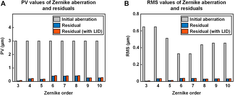
FIGURE 12. Zernike mode aberrations correction results of the lab-manufactured DDM. The correction results of original Zernike mode aberrations are marked in blue. The correction results of Zernike mode aberrations superimposed with the LID are marked in orange. (A) PV values. (B) RMS values.
4 Conclusion
In this paper, a DDM is presented to suppress the LID which occurs on the mirror surface of a DM under high-power laser irradiation. The DDM adopts the dual magnetic connection structure, using two layers of magnets to connect the mirror and the base. Configurations of the DDM are introduced, and finite element models are constructed to investigate the LID characteristics of the DDM, the HDM, and the ADM in simulation. Results show that the HDM and the ADM both have LID that could not be effectively self-corrected, while the LID of the HDM has smaller PV and RMS values and is easier to be self-corrected. The wavefront correction capability of the DDM is analyzed in simulation, taking third–10th Zernike mode aberrations as the initial distortions that need to be fitted. The results show that the LID would deteriorate the wavefront correction performance of a DM, and that the DDM suffers much smaller performance loss than the HDM. An experiment is carried out to investigate the LID of a lab-manufactured DDM. The experiment results correspond well with the simulation results, indicating that with the dual magnetic connection structure, the DDM could well suppress the LID under high-power laser irradiation and maintain good wavefront correction capability. Furthermore, the DDM requires no additional external hardware components or sophisticated correction algorithms, demonstrating good applicability to different AO systems.
Data availability statement
The raw data supporting the conclusion of this article will be made available by the authors, without undue reservation.
Author contributions
YMZ and LH contributed to conception and design of the study. YMZ performed the simulation and the experiment. YMZ, LH, YCZ, SL, DW, and YFZ contributed to writing and editing the manuscript. All authors contributed to the article and approved the submitted version.
Funding
This work was supported by the National Natural Science Foundation of China (No. 61775112).
Conflict of interest
The authors declare that the research was conducted in the absence of any commercial or financial relationships that could be construed as a potential conflict of interest.
Publisher’s note
All claims expressed in this article are solely those of the authors and do not necessarily represent those of their affiliated organizations, or those of the publisher, the editors and the reviewers. Any product that may be evaluated in this article, or claim that may be made by its manufacturer, is not guaranteed or endorsed by the publisher.
References
1. Merkle F. Synthetic-aperture imaging with the European very large telescope. J Opt Soc Am A (1988) 5(6):904–13. doi:10.1364/JOSAA.5.000904
2. van Dam MA, Le Mignant D, Macintosh BA. Performance of the keck observatory adaptive-optics system. Appl Opt (2004) 43(29):5458–67. doi:10.1364/AO.43.005458
3. Ardeberg A, Linde P. ELTs, adaptive optics and wavelengths. Proc SPIE (2008) 6986:698608. doi:10.1117/12.801259
4. Manuel AM, Phillion DW, Olivier SS, Baker KL, Cannon B. Curvature wavefront sensing performance evaluation for active correction of the Large Synoptic Survey Telescope (LSST). Opt Express (2010) 18(2):1528–52. doi:10.1364/OE.18.001528
5. Sulai YN, Dubra A. Adaptive optics scanning ophthalmoscopy with annular pupils. Biomed Opt Express (2012) 3(7):1647–61. doi:10.1364/BOE.3.001647
6. Pozzi P, Quintavalla M, Wong AB, Borst JGG, Bonora S, Verhaegen M. Plug-and-play adaptive optics for commercial laser scanning fluorescence microscopes based on an adaptive lens. Opt Lett (2020) 45(13):3585–8. doi:10.1364/OL.396998
7. Czuchnowski J, Prevedel R. Adaptive optics enhanced sensitivity in Fabry-Pérot based photoacoustic tomography. Photoacoustics (2021) 23:100276. doi:10.1016/j.pacs.2021.100276
8. Yu L, Qi Y, Li D, Xia M, Xuan L. Image restoration of the open-loop adaptive optics retinal imaging system based on optical transfer function analysis. Opt Commun (2013) 300:178–82. doi:10.1016/j.optcom.2013.03.022
9. Marcos S, Werner JS, Burns SA, Merigan WH, Artal P, Atchinson DA, et al. Vision science and adaptive optics, the state of the field. Vis Res (2017) 132:3–33. doi:10.1016/j.visres.2017.01.006
10. Burns SA, Elsner AE, Sapoznik KA, Warner RL, Gast TJ. Adaptive optics imaging of the human retina. Prog Retin Eye Res (2019) 68:1–30. doi:10.1016/j.preteyeres.2018.08.002
11. Zacharias R, Bliss E, Feldman M, Grey A, Koch J, Sacks R, et al. Wavefront control system for the national ignition facility (NIF). Proc SPIE (1999) 3749:252–3. doi:10.1117/12.354735
12. Zacharis R, Bliss E, Winters S, Sacks R, Feldman M, Grey A, et al. Wavefront control of high-power laser beams in the National Ignition Facility (NIF). Proc SPIE (2000) 3889:332–43. doi:10.1117/12.380902
13. Wang D, Hu D, Yuan Q, Xue Q, Zhou W, Yang Y, et al. Wavefront control of main-amplifier system in the SG-Ⅲ laser facility. Opt Commun (2017) 394:92–7. doi:10.1016/j.optcom.2017.03.002
14. Lubeigt W, Valentine G, Girkin J, Bente E, Burns D. Active transverse mode control and optimisation of an all-solid-state laser using an intracavity adaptive-optic mirror. Opt Express (2002) 10(13):550–5. doi:10.1364/OE.10.000550
15. Samarkin V, Alexandrov A, Borsoni G, Jitsuno T, Romanov P, Rukosuev A, et al. Wide aperture piezoceramic deformable mirrors for aberration correction in high-power lasers. High Power Laser Sci Eng (2016) 4:e4. doi:10.1017/hpl.2016.3
16. Bonora S, Pilar J, Lucianetti A, Mocek T. Design of deformable mirrors for high power lasers. High Power Laser Sci Eng (2016) 4:e16. doi:10.1017/hpl.2016.14
17. Zheng W, Wei X, Zhu Q, Jing F, Hu D, Su J, et al. Laser performance of the SG-III laser facility. High Power Laser Sci Eng (2016) 4:e21. doi:10.1017/hpl.2016.20
18. Sun L, Guo Y, Shao C, Li Y, Zheng Y, Sun C, et al. 10.8 kW, 2.6 times diffraction limited laser based on a continuous wave Nd:YAG oscillator and an extra-cavity adaptive optics system. Opt Lett (2018) 43(17):4160–3. doi:10.1364/OL.43.004160
19. Wang D, Zhang X, Dai W, Yang Y, Deng X, Chen L, et al. “1178 J, 527 nm near diffraction limited laser based on a complete closed-loop adaptive optics controlled off-axis multi-pass amplification laser system,” High Power Laser Sci Eng 9, e22 (2021). doi:10.1017/hpl.2021.3
20. Bian Q, Huang L, Ma X, Xue Q, Gong M. Effect of the particular temperature field on a National Ignition Facility deformable mirror. Opt Commun (2016) 374:119–26. doi:10.1016/j.optcom.2016.03.088
21. Xue Q, Huang L, Gong M, Feng Z, Qiu Y, Li T, et al. Research on the particular temperature-induced surface shape of a National Ignition Facility deformable mirror. Appl Opt (2013) 52(2):280–7. doi:10.1364/AO.52.000280
22. Sun C, Sun L, Zheng Y, Lin S, Huang L. Theoretical and experimental research on temperature-induced surface distortion of deformable mirror. Opt Express (2018) 26(24):32205–23. doi:10.1364/OE.26.032205
23. Zheng Y, Wang D, Dai W, Xue Q, Huang L. Simulation and experimental investigation on the temperature-induced distortion characteristics of the hybrid connection structure deformable mirror. Opt Express (2020) 28(23):35202–15. doi:10.1364/OE.403001
24. Hwang J, Kim E, Kim C, Huang J, Kim D. Effects of mirror distortion by thermal deformation in an interferometry beam size monitor system at PLS-II. Nucl Instrum Methods Phys Res Sect A Accel Spectrometers, Detect Assoc Equip (2016) 833:156–64. doi:10.1016/j.nima.2016.07.012
25. Morse KA, McHugh SL, Fixler J. Thermo-mechanical characterization of a membrane deformable mirror. Appl Opt (2008) 47(29):5325–9. doi:10.1364/AO.47.005325
26. Bruchmann C, Appelfeler M, Beckert E, Eberhardt R, Tünnermann A. Thermo-mechanical properties of a deformable mirror with screen printed actuator. Proc SPIE (2012) 8253:82530D. doi:10.1117/12.912614
27. Lv K, Zheng W, Hua W. Influence of thermal distortion in mirrors on the propagation of high power lasers. Proc SPIE (2012) 8417:84171C. doi:10.1117/12.958609
28. Ahn K, Rhee H, Yang H, Kihm H. CVD SiC deformable mirror with monolithic cooling channels. Opt Express (2018) 26(8):9724–39. doi:10.1364/OE.26.009724
29. Zhu Z, Li Y, Chen J, Ma J, Chu J. Development of a unimorph deformable mirror with water cooling. Opt Express (2017) 25(24):29916–26. doi:10.1364/OE.25.029916
30. Toporovsky V, Samarkin V, Sheldakova J, Rukosuev A, Kudryashov A. Water-cooled stacked-actuator flexible mirror for high-power laser beam correction. Opt Laser Technol (2021) 144:107427. doi:10.1016/j.optlastec.2021.107427
Keywords: adaptive optics, deformable mirror, high-power laser, beam quality, wavefront correction
Citation: Zheng Y, Zhuang Y, Lin S, Wang D, Zhang Y and Huang L (2023) Simulation and experimental investigation on the wavefront correction performance of a dual magnetic connection deformable mirror under high-power laser irradiation. Front. Phys. 11:1136349. doi: 10.3389/fphy.2023.1136349
Received: 03 January 2023; Accepted: 01 March 2023;
Published: 09 March 2023.
Edited by:
Rumao Tao, China Academy of Engineering Physics, ChinaReviewed by:
Yading Guo, Technical Institute of Physics Chemistry, ChinaPengqian Yang, Shanghai Institute of Optics and Fine Mechanics (CAS), China
Copyright © 2023 Zheng, Zhuang, Lin, Wang, Zhang and Huang. This is an open-access article distributed under the terms of the Creative Commons Attribution License (CC BY). The use, distribution or reproduction in other forums is permitted, provided the original author(s) and the copyright owner(s) are credited and that the original publication in this journal is cited, in accordance with accepted academic practice. No use, distribution or reproduction is permitted which does not comply with these terms.
*Correspondence: Lei Huang, aGxAdHNpbmdodWEuZWR1LmNu