 Liangquan Wang
 Deren Kong*
95% of researchers rate our articles as excellent or good
Learn more about the work of our research integrity team to safeguard the quality of each article we publish.
Find out more
ORIGINAL RESEARCH article
Front. Phys. , 20 March 2023
Sec. Interdisciplinary Physics
Volume 11 - 2023 | https://doi.org/10.3389/fphy.2023.1114871
Introduction: In the warhead explosion process, the ground impact vibration intensity will directly affect the target buildings and instruments safety, and it is also of great significance to accurately evaluate the ammunition explosion damage power.
Methods: In this study, the finite element numerical simulation method was used to analyze the explosion shock wave pressure and ground shock vibration velocity of TNT explosive with a mass of 100 kg∼1000 kg, and the ground transmission medium of sandy soil, C35 and C140 concrete, and the shock wave pressure and ground shock vibration velocity propagation and distribution law was clarified. Based on the explosion similarity law and dimensional analysis method, a ground impact vibration velocity theoretical calculation model with clear physical significance is established by introducing the property ground propagation medium parameters, taking into account the factors affecting the ground impact vibration velocity.
Results: The model calculation accuracy is verified by the measured data. The verification results show that the model calculation accuracy is higher than 91.8%, which improves the calculation accuracy of the explosion site ground impact vibration velocity.
Discussion: This research provides more accurate and scientific theory and data support for the ammunition explosion damage power evaluation, and provides a reference for the shock and vibration resistance performance design of instruments, equipment and buildings. It has strong engineering application value.
With the rapid development of high-energy explosive materials and charging technology, the large equivalent high-energy warhead explosion will produce strong shock vibration on the ground, which will change the instruments and equipment working performance on the test site. When the shock vibration reaches a certain strength, it will lead to vibration damage or even buildings collapse [1–3]. At present, there is no relatively mature technical data to analyze the intensity of ground impact vibration caused by warhead explosion, and the research content in this field is relatively lacking. Therefore, it is necessary to study the ground impact vibration intensity caused by high-energy warhead explosion, and clarify the impact vibration propagation and distribution law in different ground media, so as to evaluate the ammunition explosion damage power, as well as instruments and equipment design of buildings anti shock and vibration performance provides scientific and accurate theory and data support.
At present, researchers in the explosion field damage testing technology and evaluation have carried out less research on the ground shock vibration strength during the ammunition explosion, the existing research data mainly focus on the analysis of seismic waves generated by ammunition explosion. For example: Vorobiev, O [4] carried out numerical simulation of underground chemical explosion of hard rock under different constraint stresses, compared the various generation mechanisms and seismic characteristics of shear wave with the simple fault rupture process observed in the earthquake, and made clear the change law of shear wave during ammunition explosion. Ma K et al. [5] found that buildings will affect the explosive seismic waves propagation. Therefore, they established a reinforced concrete plant model, conducted explosion tests outside and inside the model, and measured the corresponding seismic wave signals. The analysis results show that the building structure existence changes the seismic wave propagation environment, makes the peak velocity have a greater attenuation, and reduces the energy contained in the high-frequency components of the frequency. Nepeina, KS. et al. [6] analyzed the acquired seismic wave curve, constructed the travel time curve of seismic wave, obtained the linear function of body wave propagation within a certain range of epicenter distance, and estimated the overall velocity of the Earth’s upper mantle and outer box. Chen Y H et al. [7] tested the seismic wave induced by ground explosion, and analyzed its time-space evolution and frequency characteristics according to the test results. It is clear that when the surface is covered with loose soil, P, S and R waves will be dispersive, and the explosive seismic wave dominant frequency band is 5∼30 Hz, higher than that of natural seismic wave. Wang L Q et al. [8] collected and analyzed the seismic wave signal generated during the cloud explosion by using the seismic wave testing system, clarified the seismic wave propagation attenuation law during the cloud explosion, and fitted the particle vibration velocity theoretical formula with the measured data. The fitting function relationship can well explain the cloud bomb explosion seismic wave propagation and distribution law. Kholodilov, AN et al. [9] analyzed the ground vibration velocity caused by large equivalent explosion, gave the effectiveness of the elliptic filter on the second-order low-frequency characteristics in the process of modeling using the velocity waveform, proved the efficiency of the model in detecting the delay error, and was able to predict the load caused by the explosion. By analyzing the site effects of blast vibration velocity and blast vibration frequency, the relationship between blast vibration velocity and blast equivalent and seismic wave propagation distance, Yang L et al. [10] obtained the characteristics of blast seismic waves in terms of wave main frequency, duration, near-field initial motion and the blast seismic waves propagation law in rock and soil and the difference between these characteristic laws and natural seismic waves. Pytel, W. et al. [11] applied the numerical simulation method to analyze the elastic wave generated by the explosion of explosives in the mining face, and verified it through the field test of the ground particle velocity and acceleration parameters, clarifying the relationship between the numerical simulation of the seismic particle velocity value and the in-situ measurement using the seismic three-component geophone. Liu H Q et al. [12], to better study the wave process in the rock and soil mass under the shallow buried underground explosion action, established a calculation model for the seismic waves movement on the free surface of semi infinite medium under the shallow buried explosion action, and clearly obtained the source displacement change laws in the horizontal and vertical directions under the same burial depth and different burial depths. Wang X D et al. [13] used ABAQUS finite element software to conduct numerical simulation on the grid structure dynamic response under the action of explosion seismic wave alone, air shock wave alone and the combination of both, analyzed three load cases impact on the grid structure dynamic response, and clarified three loads impact on the grid structure internal force. To improve the seismic waves excited quality by explosive sources in seismic exploration, Mou J et al. [14] selected air, water, fine sand and rock soil as coupling media, and conducted explosion tests in soil to compare and analyze the coupling media influence on the seismic waves characteristics. The test results show that the seismic wave energy generated by explosive source with water as coupling medium is relatively high, especially in the range of 25∼100 Hz, the energy contrast difference is more obvious. Fan P X et al. [15] adopted the common deformation theory and matrix force method to consider the interaction between lining and surrounding rock, established a fast calculation method for the underground protective structures dynamic response under the explosive seismic waves action, and analyzed the impact of surrounding rock grade, cushion parameters and load action forms on the typical straight wall circular arch structures dynamic response. The results show that the surrounding rock grade has a significant impact on the structure dynamic response. In the same year [16], they discretized the circular tunnel into a finite freedom system degree by using the concentrated mass method, considered the structure self deformation under various internal forces and the elastic half space deformation by using the matrix force method, and established the structural dynamic equation matrix. By solving the structural dynamic equation, the structural dynamic concentration factor, internal force, bending moment, displacement and other parameters are obtained. Zhao S et al. [17] took the 15 story frame structure as an example, established the space plate beam structure finite element model by using the finite element analysis software, calculated the structure natural frequency and natural vibration mode, and analyzed the high-rise frame structure dynamic response under the simulated explosion seismic waves action. According to the structural dynamic response results, the structure weak story is judged, which provides a reference for the project seismic design. Zhang X J et al. [18] used LS-DYNA to conduct explosion process numerical simulation in the closed rock mass, and obtained the law of the ground vibration acceleration changing with time, which provides a certain reference for the research and calculation method of the explosion seismic wave response effect on the ground structure.
At present, the commonly used formula for calculating the explosive seismic wave ground particle vibration velocity is Sadovsky’s particle vibration velocity formula [19]. This formula does not consider the ground medium effect on the vibration velocity, and the calculation formula is only applicable to the small equivalent calculation, conventional warhead explosive seismic wave vibration velocity. When the type of ground medium, charge type and charge mass of warhead change greatly, the theoretical calculation formula accuracy will be greatly reduced, and the calculation results cannot reflect the ground impact vibration strength. In view of these problems in the current research process, it is very necessary to carry out research on the ground impact vibration intensity model during the high energy warhead explosion.
In this study, the finite element numerical simulation was carried out for the explosion shock wave and ground shock vibration velocity of the high-energy warhead with the equivalent TNT explosive mass in the range of 100 kg∼1,000 kg in the ground medium of sandy soil, C35 and C140 concrete by using the display explosion dynamics simulation software, and the propagation and distribution laws of the shock wave pressure and ground shock vibration velocity at different measuring points were analyzed. Based on the explosion similarity law and the dimensional analysis method, the impact vibration strength model with clear physical significance is established by introducing the ground propagation medium properties, and the strength model calculation accuracy is verified by using the measured data.
When the warhead explodes, the explosive products sharp collision results in the surrounding air intense compression, resulting in the local high-pressure wave front at the interface between the explosive products and the air. This wave front is the initial shock wave formed. As the explosion time goes by, the wave front gradually spreads to the distance. If the wave front does not encounter the ground or other obstacles in the propagation process, the wave front will continue to move towards the distance in the form of spherical waves. When the wave front contacts the ground, the shock wave will collide with the ground, reflecting, and form a reflected shock wave. During the collision between the shock wave and the ground, part of the incident shock wave energy will be transferred to the ground to form explosive seismic wave, which will make the ground vibrate; Because the shock wave front propagates at hypersonic and supersonic speeds in the initial propagation process, the shock wave front has a strong impact effect when contacting the ground, and the impact effect will also cause the ground to vibrate. It can be seen that, as the explosion time goes by, the shock wave front will continuously act on the ground to generate shock vibration during the propagation process. Therefore, the shock vibration source in the whole ammunition explosion process can be shown as Figure 1.
FIGURE 1. Ground propagation medium shock vibration sources.
The finite element numerical simulation analysis of the high energy warhead explosion shock wave pressure and shock vibration under different ground propagation media is carried out by using the display explosion dynamics simulation software AUTODYN. The high energy warhead equivalent TNT explosive mass is 100 kg∼1,000 kg, the explosive length diameter ratio is 1:1, the initiation mode is the center point initiation, the explosive height from the ground is 1.5 m, and the mesh size is 1 mm × 1 mm, the mesh type is Euler. The visible air area structure size is 20,000 mm × 8,000 mm (long × width), grid division size is 5 mm × 5 mm, the total number of air domain grids is 6400000, the mesh type is Euler. The ground transmission medium is sandy soil, C35 and C140 concrete respectively, and the model structure size is 20,000 mm × 4,000 mm (long × width), grid division size is 5 mm × 5 mm, the total number of ground propagation media grids is 3200000, the grid type is Lagrange. Since the air and ground propagation media mesh types are different, Euler Lagrange automatic coupling needs to be set, so as to simulate the energy conversion of explosion shock wave in the process of collision with the ground. To simulate the semi infinite air region under the actual explosive environment, the air model upper and left boundaries are set as pressure outflow, that is, no pressure reflection is generated. To obtain the data of shock wave pressure and ground shock vibration velocity at different explosion center distances, Gauges monitoring points are set every 500 mm on the ground propagation medium upper surface. Because the finite element numerical simulation model is divided into a large number of meshes, with a high density of meshes, and there is a certain overlap between each module, the finite element numerical simulation model that has been divided into meshes is not conducive to distinguishing each module in the model, so the structural schematic diagram of the finite element numerical simulation model is selected for display, and the structural schematic diagram is shown in Figure 2. The blue color in the model upper part represents the air domain, the green color in the lower part represents the ground propagation medium, the cyan part in the air domain represents the TNT explosive, and the red squares on the ground propagation medium upper surface represent the Gauges monitoring points set up.
FIGURE 2. Shock wave pressure finite element numerical simulation model structural schematic diagram.
In the above simulation model, air is an ideal gas, which is described by the Ideal Gas state equation, as shown in Eq. 1 [20].
where
TABLE 1. Ideal gas parameters.
The TNT explosive explosion process is described by JWL state equation, which is shown in Eq. 2 [23, 24].
where

TABLE 2. JWL state equation parameters.
The sandy soil strength model is Hydro (Prmin), and the failure model is Mo Granular [25]. The concrete materials strength model and failure model are both RHT models. The model introduces three limit surfaces, namely, elastic limit surface, failure surface and residual strength surface [26], which respectively describe the change rule of initial yield strength, failure strength and residual strength of concrete. Therefore, RHT model can well reflect the concrete impact vibration process under the impact wave pressure.
The established finite element numerical simulation model is used to obtain the variation rules of shock wave pressure and ground vibration velocity at different measuring points. As the finite element numerical simulation of 100 kg∼1,000 kg equivalent TNT explosive mass was carried out in the actual simulation process, many shock wave pressure time history curves were obtained, which could not be displayed here one by one. Therefore, we take the time history curve of shock wave pressure obtained when the TNT explosive mass is 100 kg and 1,000 kg, and the ground transmission medium is sandy soil as an example to show. The time history curve of shock wave pressure obtained is shown in Figure 3.
FIGURE 3. Shock wave pressure time history curve. (A) 100 kg TNT. (B) 1,000 kg TNT.
It can be seen from Figure 3 that under the same TNT explosive mass, the shock wave pressure peak value decreases gradually with the distance increase between the measuring points. With the TNT explosive mass increase, the shock wave pressure peak value at the same measuring point increases, that is, the shock wave pressure peak value is negatively correlated with the distance between measuring points, and positively correlated with TNT explosive mass. To verify the calculation results reliability of the finite element numerical simulation model established above, the measured ground reflection pressure data obtained when the TNT explosive mass is 100 kg, the explosive is 1.5 m above the ground, and the distance between the measuring point and the vertical projection point of the blast center is 4, 7, 9, 11, 13, and 16 m respectively, are compared with the peak ground reflection pressure obtained from the finite element value in this study. The measured shock wave pressure peak and the shock wave pressure peak obtained by numerical simulation are shown in Figure 4A, and the shock wave pressure peak relative error rate at different measuring points is shown in Figure 4B. The formula for calculating the pressure peak relative error rate is shown in Eq. 3.
FIGURE 4. Comparison between measured results and numerical results. (A) Measured and numerical simulation shock wave pressure peak. (B) Measured and numerical simulation shock wave pressure peak error.
According to the comparison between the above numerical simulation results and the measured results, when the TNT explosive mass is 100 kg, the peak value of shock wave pressure obtained by the finite element numerical simulation and the measured peak value of shock wave pressure decay with the increase of the distance between the test point and the blast core remain highly consistent, as shown in Figure 4A. The shock wave pressure peak value quantitative analysis at different measuring points found that the maximum relative error between the finite element numerical simulation results and the measured results occurred at the distance between the measuring point and the blast center of 7 m, the maximum relative error rate was 6.07%, the minimum relative error rate occurred at the distance between the measuring point and the blast center of 13 m, the minimum relative error rate was 2.15%, and the shock wave pressure peak value relative error rate at other measuring points was between the two, as shown in Figure 4B. It can be seen that the finite element numerical simulation calculation accuracy meets the accuracy requirements for the explosion field damage test numerical simulation results. Therefore, the finite element numerical simulation model established above can be used to analyze the shock wave pressure propagation distribution law and the shock vibration velocity distribution law during the ammunition explosion process.
To analyze the distribution law of shock wave pressure and shock vibration velocity under different surface propagation media environments, the numerical extraction of finite element numerical simulation results is carried out to obtain the shock wave pressure peak change law multi factor index histogram as shown in Figure 5, and the surface shock vibration velocity peak change law curve as shown in Figure 6.
FIGURE 5. Shock wave pressure peak value change law. (A) 100 and 500 kg shock wave pressure peak variation law. (B) 700 and 1,000 kg shock wave pressure peak variation law.
FIGURE 6. Ground vibration velocity peak curve. (A) Ground medium is sandy soil. (B) Ground medium is C35 concrete. (C) Ground medium is C140 concrete.
Based on the analysis of the propagation and distribution law of the obtained shock wave pressure and ground vibration velocity, the effect of the TNT explosive mass increase on the shock wave pressure peak value is obviously higher than that on the ground vibration velocity peak value, which is due to the different mechanisms of the two kinds of explosion damage parameters. For the explosion shock wave, the TNT explosive mass increase will directly lead to the explosion products increase, and the surrounding air compression during the explosion products collision will be significantly enhanced, so the shock wave pressure peak value will be significantly larger; For the ground impact vibration velocity, the impact vibration velocity is due to the impact between the shock wave and the ground when it propagates to the ground, and part of the shock wave energy is converted into the ground propagation medium energy, which makes the ground propagation medium vibrate. Although the explosion shock wave pressure energy will increase with the TNT explosive mass increase, and the energy converted from the shock wave energy to the ground medium during the collision process will also increase, the energy conversion rate during the collision process is a certain value, which is directly related to the wave impedance of the ground medium and the air medium. When the two propagation media are not changed, the energy conversion rate during the collision process is also fixed. Therefore, with the TNT explosive mass increase, the ground propagation medium shock vibration velocity peak value will increase, but the growth rate will be smaller than that of the shock wave pressure peak value.
With the ground propagation medium change, the peak value of shock wave pressure and ground shock vibration velocity of the same TNT explosive mass at the same measuring point are different, that is, the ground propagation medium material properties will affect the shock wave pressure and shock vibration velocity. For the ground medium of sandy soil, C35 and C140 concrete, the shock wave pressure peak value at the same TNT mass and the same measurement point position is
According to the above energy conversion principle, the shock wave pressure peak at the far field is smaller, the shock wave on the ground propagation medium particle compression is also reduced, the compression process into the ground propagation medium energy will also be reduced, resulting in more residual energy, reflected in the ground propagation medium vibration velocity peak decay rate is slower, the distance propagation is farther. Therefore, with the increase in the distance between the measurement point and the burst center, the shock wave pressure peak and the ground medium shock vibration velocity peak decay rate will gradually decrease.
Through the above analysis and in combination with the explosion impact dynamics relevant theory, the main factors that affect the ground impact vibration velocity in the ammunition explosion process are: shock wave pressure peak value
The three basic physical quantities L (length)—M (mass)—T (time) are selected to analyze the expressions of the above physical quantities each scale, and the each physical quantity scale expressions are shown in Table 3.
TABLE 3. Expressions for the each physical quantity magnitude.
Combine the vibration velocity
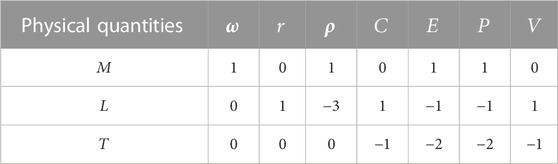
TABLE 4. Each physical quantity dimension power index.
Comprehensively consider the dimensional form and physical meaning of each physical quantity, the explosive mass, the distance
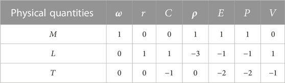
TABLE 5. Each physical quantity dimension power index.
Based on the selected reference physical quantities,
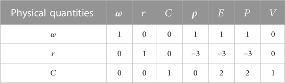
TABLE 6. Each physical quantity dimension power index (after sorting).
From the each physical quantity power in Table 6, the four dimensionless physical quantities are
The above four dimensionless physical quantities combination can be obtained as a function of Eq. 6.
The dimensionless functional relationship in Eq. 6 is simplified to obtain the functional relationship shown in Eq. 7.
According to the relevant theory in the materials mechanics, it is known that the product of the material density
Equation 8 is the ground shock vibration velocity intensity model during the ammunition explosion. From this intensity model, it can be seen that the ground shock vibration velocity is positively correlated with the peak shock wave pressure
To determine the above functional relationship final expression, the functional relationship in Eq. 8 is expressed in the form shown below.
The shock wave pressure and ground shock vibration velocity data obtained from the finite element numerical simulations carried out in different ground media with different TNT masses were used to obtain the coefficients values
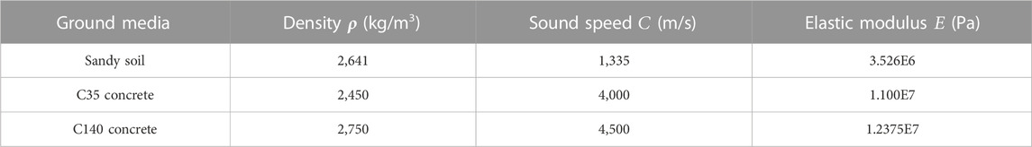
TABLE 7. Ground propagation medium material property parameters.
FIGURE 7. Functional relationship fitting effect.
According to the fitting effect diagram of the above function relationship, the data fitting error squares sum is 0.97488, and the adjustment error squares sum is 0.97423. When
In Eq. 9, the undetermined coefficients
To verify the above functional relationship model calculation accuracy, we carried out the field test under the condition that the surface propagation medium is sandy soil and the high-energy warhead equivalent TNT explosive mass is 300 kg and 500 kg. The surface reflection pressure measurement system and the ground vibration velocity measurement system are shown in Figures 8, 9.
FIGURE 8. Surface reflection pressure measuring system.
FIGURE 9. Ground vibration velocity measurement system.
The ground reflection pressure measurement system is composed of ground reflection pressure sensor, sensor installation component, self-developed high-precision synchronous trigger controller, TranNet 308S data collector and computer terminal. The measurement system can realize data acquisition at a sampling rate of 1 MS/s for 32 channels at the same time. The ground vibration speed measurement system is composed of unidirectional magnetoelectric speed sensor, speed sensor mounting rod, TC-4850 vibration meter and computer terminal. A TC-4850 vibration meter can be connected to three speed sensors at the same time. The vibration meter has a built-in power supply, which can realize continuous acquisition for a long time.
The above measuring system is used to obtain the ground reflection pressure and the ground impact vibration velocity variation law generated during the ammunition explosion process. When the equivalent TNT explosive mass is 300 kg, the horizontal distance between the measuring point position and the vertical projection point of the blast center is 3.5, 5, 6, 6.5, and 8 m respectively; When the equivalent TNT explosive mass is 500 kg, the horizontal distance between the measuring point position and the vertical projection point of the blast center is 4, 4.5, 7, 7.5, and 9 m respectively. The incident angle of shock wave pressure is equal to the horizontal distance between the measuring point and the vertical projection point of the blast center divided by the arctangent function of the blast height. According to the calculation, the pressure monitoring points at the measuring points of 7, 7.5, 8, and 9 m in the above verification data are located in the Mach reflection zone. The peak value of ground vibration velocity obtained during the test and the peak value of ground vibration velocity calculated by Eq. 10 are shown in Table 8.
TABLE 8. Ground vibration velocity peak data.
Through comparison and analysis of the data in Table 8, it can be found that the peak value of ground vibration velocity obtained by the ground vibration velocity measurement system is very close to the calculation result of the functional relationship model of Eq. 10, and the ground vibration velocity overall change rule is consistent. The individual data calculation results in the above data are somewhat different from the measured results. The main reason is that the test site surface propagation medium is not completely homogeneous. The test site is affected by the mixed stones, rubble in the soil and the elevation difference within the region, resulting in the change of the ground vibration velocity peak value, as a result, the relative error between the calculated and measured results of ground vibration velocity at some measuring points is large. The relative error rate between the ground vibration velocity calculated results at different measuring points and the measured results is shown in Figure 10. The formula for calculating the relative error rate is shown in Eq. 11.
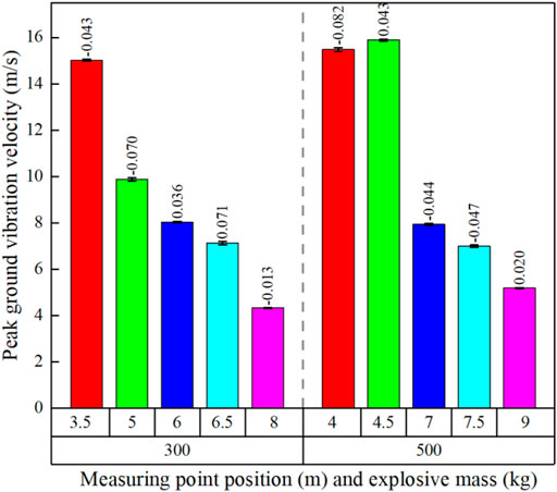
FIGURE 10. Measured data and calculated results relative error diagram.
It can be seen from the relative error results between the above measured values and calculated values that the maximum relative error occurs at the TNT explosive mass of 300 kg, the distance between the measuring point and the explosion center is 8 m, which is 1.3%, the minimum relative error occurs at the TNT explosive mass of 500 kg, the distance between the measuring point and the explosion center is 4 m, which is 8.2%, and the relative errors at other measuring points are between them. It can be concluded that the calculation accuracy of the above established ground impact vibration velocity calculation function is better than 91.8%. This function relationship improves the ammunition explosion ground impact vibration velocity calculation accuracy, provides scientific data support for the high-energy warhead explosive damage power test, and has strong engineering application value.
This study carried out a finite element numerical simulation analysis of the shock wave pressure and ground medium shock vibration velocity propagation distribution law during the high-energy warhead explosion. The effects of TNT explosive mass and ground medium type on shock wave pressure and vibration velocity are analyzed. Based on the explosion similarity law and the dimensional analysis method, the high energy warhead explosion ground impact vibration velocity calculation model is established. This study results indicate that:
(1) The ground medium has a significant effect on the propagation and distribution of shock wave pressure and ground shock vibration velocity. When the ground medium is sandy soil, C35 and C140 concrete, under the same explosive environment, the shock wave pressure peak value and the ground vibration velocity peak value are
(2) Based on the explosion similarity law and the dimensional analysis method, the introduction of shock wave pressure peak
This research results clarify the distribution law of high-energy combatant explosion shock wave pressure and ground shock vibration velocity propagation, and provide theoretical support for the munition explosion damage power test program design. The established ground shock vibration velocity calculation model provides scientific data support for accurate assessment of the ammunitions damage power and guidance for the instruments design, equipment and buildings against shock vibration.
The original contributions presented in the study are included in the article/supplementary material, further inquiries can be directed to the corresponding author.
LW: Conceptualization; data curation; formal analysis; methodology; software; writing–original draft; FS:writing—review and editing; validation. DK: Project administration; writing—review and editing; resources. All authors contributed to the article and approved the submitted version.
This work was funded by National Equipment Program of China, project number: 14021001050206.
The authors declare that the research was conducted in the absence of any commercial or financial relationships that could be construed as a potential conflict of interest.
All claims expressed in this article are solely those of the authors and do not necessarily represent those of their affiliated organizations, or those of the publisher, the editors and the reviewers. Any product that may be evaluated in this article, or claim that may be made by its manufacturer, is not guaranteed or endorsed by the publisher.
1. Hu BY, Xiao ZQ, Gu Y, Liu Y, Feng DS, Liu J. Vibration monitoring and analysis of 40kg TNT equivalent explosive tower[J]. Explosion and Shock (2018) 38(04):918–24.doi:10.11883/bzycj-2016-0260
2. Hu QW, Wang GY, Shi Q, Tian X. Simulation study on damage of electronic equipment under explosion shock vibration environment[J]. J Mil Eng (2012) 33(01):13–8.
3. Hu BY, Liu CL, Chen SY, Liu Y, Lou ZH, Wang LJ. Shock isolation study of 25 kg TNT equivalent explosive container [J]. Vibration and Shock (2006)(06) 43–5+177.
4. Vorobiev O. On various mechanisms of shear wave generation from underground chemical explosions in hard rocks[J]. Geophys J Int (2023) 232(03): 232.
5. Ma K, Chen YH, Chen J, Zeng D, Zhang SH, Gou RJ. Effect of buildings on the propagation of seismic waves from explosions [J]. Sci Tech Eng (2021) 21(23):9940–6.
6. Nepeina KS, An VA. Travel time curves of seismic waves from underground explosions on amchitka island[J]. Acoust Phys (2022) 67(6).
7. Chen YH, Ma K, Chen J, Zeng D, Zhang SH, Gou RJ. Evolution and frequency characteristics of ground explosion seismic waves[J]. Ind Saf Environ Prot (2021) 47(05):13–5.
8. Wang LQ, Shang F, Kong DR. Research on the testing method of seismic wave of a certain type of cloudburst bomb explosion[J]. J Test Tech (2020) 34(05):376–80.
9. Kholodilov A, Gospodarikov AP. Modeling seismic vibrations under massive blasting in underground mines. J Mining Scinece (2020) 56(1):29–35. doi:10.1134/s1062739120016454
10. Yang L, Han Y, Tang Q, Gao P. Analysis of mechanism and site effects of explosive earthquakes[J]. Gansu Sci Tech (2017) 33(18):37–41.
11. Pytel W, Mertuszka P, Lurka A, Fulawka K, Szumny M. Seismic peak partcile velocity and acceleration response to mining faces firing in a light of numerical modeling and underground measurements[J]. Arxiv (2019). p. 11.https://arxiv.org/abs/1903.04232
12. Liu HQ, Yang HD. The law of motion of explosive seismic waves on the free surface of semi-infinite medium[J]. J Liaoning Univ Eng Tech (Natural Sci Edition) (2015) 34(02):186–91.
13. Wang XD, Dong XP, Chen ZH, Liu HB, Zhang J, Chang L. Dynamic response of grid structure under the combined action of explosion seismic wave and air shock wave[J]. Ind Architecture (2016) 46(09):169–74.
14. Mou J, Wang ZQ, Yu CL. Experimental study on the influence law of coupling medium on the seismic wave energy and main frequency of explosive source explosion[J]. J Mil Eng (2014) 35(S2):115–21.
15. Fan PX, Wang MY, Feng SF, Li J, Wang DR. Dynamic response of straight-walled vaulted underground structures subjected to blast seismic waves[J]. Vibration and shock (2014) 33(22):183–7.
16. Fan PX, Wang MY, Feng SF, Wang J, Wang DR, Li J. Analysis of dynamic response of deeply buried circular tunnel under the action of explosive seismic waves[J]. J Rock Mech Eng (2013) 32(04):671–80.
17. Zhao S, Feng ZQ. Simulation of explosion seismic wave and its effect on frame structure[J]. J Shaanxi Inst Sci Tech (Natural Sci Edition) (2010) 26(04):42–7.
18. Zhang XJ, Shi SQ, Yin P, Liu YF. Numerical simulation of the effect of blast seismic wave on ground structure[J]. Blasting (2004) 21(01): 5–8.
19. Chai XW. Effects of different explosive properties on blasting vibration effects[J]. Explosion and Impact (2011) 31(05):548–52.
20. Wang LQ, Shang F, Kong DR. Effect of sensor installation angle on measurement of explosion shock wave pressure. Meas Sci Technol (2021) 33(11):115023. doi:10.1088/1361-6501/ac88eb
21. Wang LQ, Kong DR. The influence of sensor installation angle on explosive shock wave overpressure test[C]. 53rd Int Conf Vibroengineering (2021) 39:127–32.
22. Wang LQ, Kong DR. Influence of ground impedance on explosive shock wave test accuracy. Int J Impact Eng (2022) 171:104395. doi:10.1016/j.ijimpeng.2022.104395
23. Kong XF, Wang LQ, Yu T, He Z, Luo H, Li B. Free-field shockwave test method for meteorological air cannons. [J] Meas (2021) 189:110456. doi:10.1016/j.measurement.2021.110456
24. Fan CF, Yang KZ, Mao W, Jinghua H, Xinwei L. Research on attenuating mechanism of wave-eliminating interceptor on explosion shock wave in tunnel engineering. IOP Conf Ser Mater Sci Eng (2020) 758:758. doi:10.1088/1757-899x/758/1/012012
25. Zhu JQ, Wang YQ, Wang YJ, Zhang HL, Li YP, Liu Y. Analysis of root reinforced shear strength based on experiments and models[J]. Geotechnical Mech (2014) 35(02):449–58.
Keywords: shock vibration, numerical simulation, dimensional analysis, strength model, pressure distribution law
Citation: Wang L, Kong D and Shang F (2023) Study on the ground impact vibration intensity model of high energy warhead explosion. Front. Phys. 11:1114871. doi: 10.3389/fphy.2023.1114871
Received: 03 December 2022; Accepted: 06 March 2023;
Published: 20 March 2023.
Edited by:
Ferenc Kun, University of Debrecen, HungaryReviewed by:
Yu Sun, Xi’an Jiaotong University, ChinaCopyright © 2023 Wang, Kong and Shang. This is an open-access article distributed under the terms of the Creative Commons Attribution License (CC BY). The use, distribution or reproduction in other forums is permitted, provided the original author(s) and the copyright owner(s) are credited and that the original publication in this journal is cited, in accordance with accepted academic practice. No use, distribution or reproduction is permitted which does not comply with these terms.
*Correspondence: Deren Kong, a2RyNDUwMDI1ODkwQDE2My5jb20=
Disclaimer: All claims expressed in this article are solely those of the authors and do not necessarily represent those of their affiliated organizations, or those of the publisher, the editors and the reviewers. Any product that may be evaluated in this article or claim that may be made by its manufacturer is not guaranteed or endorsed by the publisher.
Research integrity at Frontiers
Learn more about the work of our research integrity team to safeguard the quality of each article we publish.