 Chunxia Yang
- Plastic and Cosmetic Surgery, Sanya Traditional Chinese Medicine Hospital, Sanya, Hainan, China
With the improvement of medical levels and the continuous improvement of people’s living standards, the demand for beauty by the general public is increasing. The plastic surgery industry has also developed by leaps and bounds. People’s dissatisfaction with their own facial appearance, facial injuries and some other reasons have prompted people to carry out facial reconstruction, and facial plastic surgery has developed rapidly. However, in the current facial plastic surgery, the edge detection effect on the contour image is general. In order to improve the edge detection effect of facial contour lines in medical images, this paper proposed a facial contour line generation algorithm. First, the detection effects of four operators were compared. After comparing the effects, the Sobel operator was used as the input data to generate an edge detection algorithm. Then, the grayscale features of the tissue in the image and the symmetry of the image were used to perform bidirectional contour tracking on the detected image to extract facial contour lines. In addition, for facial contour features, the midpoint method can be used to generate auxiliary contours. The algorithm was verified by a set of facial CT (Computed Tomography) images in the experiment. The results showed that the new generation algorithm accelerated the edge detection speed, had good denoising performance, and enhanced the edge detection effect by about 12.05% compared with the traditional edge detection algorithm. The validity and practicability of facial edge detection were verified, and it provided a theoretical basis for further realizing the design of a facial contour digital image processing system.
1 Introduction
Facial plastic surgery has an important position as a major branch of plastic surgery. Due to the irregular contours of the human face, the correction of facial structural parameters, facial measurement, and structural analysis are both key and difficult points in plastic surgery. With the continuous development of face detection and recognition technology based on digital images, the detection of facial feature parameters has also begun to enter the medical field, and various studies have provided new ideas and solutions for problems such as facial image edge detection and image segmentation.
Now there is some research on image edge detection algorithms by scholars. Luo C proposed an improved algorithm based on Canny edge detection and grayscale difference preprocessing to solve the problems of traditional image edge detection algorithms with low efficiency and accuracy, poor anti-noise ability, and the need to set thresholds manually [1]. According to whether the dataset contains intuitive label features, Zhang Q split current deep learning-based edge detection techniques into supervised learning-based image edge detection method and unsupervised learning-based image edge detection method [2]. An edge identification technique based on the binary wavelet transform and the morphological operator was suggested by Zhi-Bin H U, the accurate data extraction and recognition analysis of the front image of the face contour can be realized through the binary wavelet change [3]. To create a novel picture edge identification technique, Feng J multiplied the wavelet coefficients of the nearby scale products and identified the local modulus maximum point of the scale product coefficients as an edge, the application of image edge recognition technology to the edge detection of facial contour frontal image can effectively improve the accuracy of facial image detection [4]. On a board with a field programmable gate array, Menaka R suggested a filter-based edge detection approach [5]. With contour detection at its core and the green channel data from the eye image as input, Rujov F created a fuzzy rule based on Mamdani (Type-2) theory [6]. To segment an image, edge detection is essential. A typical Canny operator-based edge identification technique for medical images has been studied by Xu Z. The Canny operator’s edge detection is enhanced, and the double-gate limit detection approach enhances the Canny operator’s edge detection. MATLAB simulates the process on a computer platform, and the mean square error and information entropy are used as two objective evaluation indices to evaluate the experimental results. The experimental findings demonstrated that the enhanced adaptive double-threshold Canny algorithm has superior edge detection performance than the conventional Canny method, the image details are rich, the noise suppression effect is good, and the error edge is less [7]. The above research analyzed the image edge detection algorithm.
Many scholars have studied image segmentation. Sami R generated fresh-keeping antibacterial technology by studying microscopic image segmentation and morphological characterization [8]. Suban I B used the level set function to capture the boundaries between objects contained in the image, combined the lattice Boltzmann method with fuzzy clustering, and used the graphics processing unit for parallel processing to speed up the image segmentation process [9]. Li H A employed the AdaBoost algorithm with the Gabor texture analysis algorithm to separate images with several faces, significantly lowering the face image segmentation’s false detection rate [10]. Rangayya put forth a brand-new face recognition model. Four primary components make up the suggested method: data collection, segmentation, feature extraction, and recognition [11]. For face segmentation and 3D face reconstruction, Yin X suggested a new face masking model that can automatically remove all borders, even blurring face masking. A 3D face reconstruction module, a face segmentation module, and an image creation module are all included in the suggested model [12]. The research of the above scholars has achieved fruitful progress in image segmentation.
The foundation of image processing in medicine is the edge detection of medical pictures. The accuracy of the edge detection result directly affects how easily the picture may be processed later. Due to the complexity and variety of medical images, there is currently no universal segmentation method, and only appropriate algorithms can be designed according to specific applications and image characteristics. This paper aims to improve the speed, accuracy, and contour segmentation effect of facial contour image segmentation in plastic surgery, to design and study related algorithms.
2 Facial image preprocessing
2.1 Preprocessing process
From an information-theoretic point of view, the best results are obtained without preprocessing since preprocessing reduces the amount of information in the image [13]. Preprocessing refers to the preparation process before final processing and improvement. Specific applications in different industries or fields will have different interpretations. In the process of image processing, preprocessing will perform feature extraction, segmentation and matching on the input image. Therefore, work should focus on processing high-quality image data when conditions permit. However, preprocessing is not unsatisfactory, and it can suppress the deformation of the image and strengthen the image features required for subsequent processing [14].
Grayscale transformation can convert pixels to grayscale. If the image grayscale is within a small range, grayscale conversion can be performed on the image to achieve a higher grayscale. The pixel undergoes coordinate transformation and grayscale interpolation in its neighborhood to obtain a new bit of grayscale.
Local preprocessing creates fresh pixel grayscales. Local preprocessing can be split into two groups depending on the goal. Image enhancement is one, and image smoothing is another. Image grayscale transformation is the process of transforming the grayscale value of each point in the original image into another grayscale value according to a specific mapping function. The smoothing phase is low-pass filtering since the goal of smoothing is to reduce noise, which is typically high frequency. Smoothing, however, eliminates this portion of high-frequency information because the spatial distribution of the image grayscale function still contains high-frequency components (such as edges, corners, and lines). Conversely, image enhancement aims to emphasize image details (i.e., edges, lines, and corners), that is, to enhance the high-frequency parts of the image, but this also produces an enhanced effect on image noise. Simple smoothing and enhancement are not ideal, and this article looks for a way to balance the two.
2.2 Image reading
The images use the DICOM standard. The (National Electrical Manufacturers Association) and (the American College of Radiology) jointly established the DICOM (Digital Imaging and Communications in Medicine) standard, which is utilized in the disciplines of digital medical imaging and communications [15]. In the past, the operation of CT images was to send the CT film into the computer by scanning, photographing, and other means, and save it in bitmap format to obtain a two-dimensional image and display it. However, when viewing the original CT image directly, part of the facial feature information will be lost due to the characteristics of the CT image itself. In film scanning and transferring data, it is easy to lose a lot of information and affect the subsequent operation effect. Matlab7 especially provides the function of reading DICOM images, which can directly read CT images and reduce the loss of information [16]. To this end, this paper uses Matlab to program image operations such as CT image reading and display. Because CT images contain some useless information, they all need to be preprocessed. In the preprocessing operation, the multiplication function shields the useless information and saves the useful fault information.
2.3 Image enhancement
Due to the physical characteristics of X-rays, the gray distribution of muscle and soft tissues in medical CT images is narrow, and the contrast between the target and the background is low, which is not conducive to identification [17]. Direct viewing of the original CT image is easy to ignore some detailed information, which is not conducive to the extraction of facial contours. Histogram equalization is one of the techniques of grayscale transformation, and it is a powerful means to improve image brightness [18]. The contrast of the image after histogram equalization is significantly enhanced. The histogram changes are shown in Figure 1.
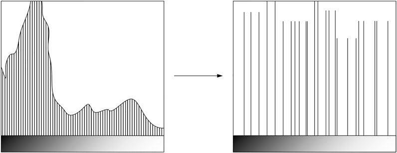
FIGURE 1. Histogram change.
The abscissa of the histogram represents 0–255 gray levels, and the ordinate represents the number of pixels corresponding to this gray level. It can be seen from Figure 1 that the pixels with gray levels between 0 and 50 in the histogram before equalization account for the vast majority, and the pixels in the histogram after equalization are more evenly distributed in the entire gray range. In addition, the histogram equalization technique can increase the contrast around the maximum value of the histogram and reduce the contrast around the minimum value.
Histogram equalization is a convenient and efficient image enhancement technology. It alters the picture histogram to realize the change in each pixel’s level of gray and is mostly used to boost dynamic range and image contrast. Due to the grey distribution’s concentration in a tiny area, the original image may not be clearly defined. In a photograph that has been overexposed, for example, the distribution of the grey level is mostly in the high brightness range, but in a shot that has been underexposed, the distribution would be in the low brightness range. Histogram equalisation aims to increase the dynamic range of the difference in grey values between pixels and improve the overall contrast of the image by converting the original picture histogram into an equally distributed and equalised form.
3 Construction of edge detection algorithm
3.1 Edge detection
After acquiring the enhanced image, image edge detection is required. In practical applications, the edge contains most of the information in the image, and the information of the facial contour that needs to be found is contained in the edge of the image. Therefore, extracting image edges reliably and effectively is a preprocessing measure that must be taken. Figure 2 shows some typical edge profiles.
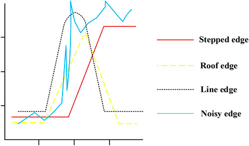
FIGURE 2. Typical edge profile.
Edges are defined as vectors, and for image function points, the edge size is the image function gradient size. The direction is the direction of rotation along the gradient direction. The edge direction is perpendicular to the gradient direction, and the measure is equal to the gradient magnitude. The edge of an image refers to the part of the image where the brightness changes significantly in a local area. The gray level profile of this area can generally be seen as a step, that is, from a gray level value that changes sharply in a small buffer area to another gray level value with a large difference in gray level. In fact, edge detection is divided into two layers, one of which is to locate the position of the edge, and the other is to measure the size of the edge. For an image, in the area where the gray level is uniform, the edge is 0 or approximately 0; however, in the area where the gray level of the image changes, there must be an edge where it changes. In this paper, the image function gradient is used to detect the change in the image function, and then the edge is detected. Gradient-based edge detection operators include the Robert operator, Laplace operator, Sobel operator, and LoG operator based on the zero-crossing point of the second derivative.
3.2 Comparison of four operators and their effects
1), The Robert operator only uses the
This operator is also known as the intersection operator because it approximates its first-order partial derivative by using the intersection of the current pixel. This operator uses a small neighborhood, which makes it more vocally sensitive [19]. Additionally, because of its even size, the operator’s predicted neighborhood is asymmetrical to the present pixel, producing an unsatisfactory outcome. 2) Laplace operator.
The Laplace operator approximates the second-order partial derivative of the image function at the current pixel, and its size is
It is discretized, as shown in Formula (3):
In the formula
Various coefficients are proposed to create geometric modeling:
The diagonal direction is added to the definition, resulting in the following:
Since the Laplace operator calculates the second derivative of the image function, it is very sensitive to noise and has a double response to some edges in the image.
3.3 Sobel operator
The Sobel operator uses a convolution modulus of
3.4 LoG operator
Image
The definition of the Gaussian filter is shown in Formula (7):
Among them
It is discretized to obtain the mask off
Comparison: it can be seen that the test results according to the first derivative test operator (Robert operator, Sobel operator, etc.) are acceptable, the noise of the two images is small, and the testing effect according to the second derivative test operator (Laplace operator) is not ideal. Higher-order derivatives are more sensitive to grayscale changes. The LoG operator has the highest level of edge detecting capability. However, based on the demands of the ensuing segmentation algorithm, the detection effect is poor because of a lot of extraneous data. This research ultimately decides to use the Sobel operator as the foundation for algorithm optimization after assessing the detection performance of each operator.
4 Facial contour segmentation
4.1 Facial contour generation
The result of the new facial edge detection algorithm proposed in this paper finally leads to contour tracking, through which accurate and clear facial contours can be obtained. In the face CT image segmentation, firstly, the appropriate threshold is set according to the facial soft tissue’s gray characteristics, and each CT image’s edges are detected to obtain a series of edge detection images. Then, the gradient magnitude of each pixel in the image is calculated so that the gray value of each pixel is equal to the gradient magnitude of the point. Finally, the starting point of the contour in the image after edge detection is identified, and the facial edge is detected by bidirectional tracking to obtain the contour of the facial soft tissue. In the bidirectional tracking detection of facial edges, edges are a kind of underlying features of images. The accuracy of facial image contour detection can be improved through bidirectional feature detection. The generation steps of the entire facial contour line are shown in Figure 3.
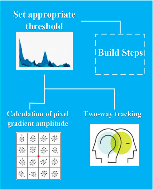
FIGURE 3. Steps for generating facial contour lines.
4.2 Bidirectional contour generation
After performing Sobel edge detection on the image, the edges of the tissue in the image are obtained. In view of these characteristics, this paper improves the contour tracking algorithm and realizes the bidirectional tracking of facial contours. The pixel position coordinates are shown in Table 1.
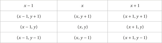
TABLE 1. Pixel position coordinates.
In order to reduce the tracking time, the bidirectional tracking method is adopted in this paper. In the two-way tracking process, synchronous tracking is performed in two directions, clockwise and counterclockwise, and the two are parallel. Clockwise is to track the right half of the image contour, and counterclockwise is to track the left half of the image contour. Tracking in a clockwise direction is called right tracking, and tracking in a counterclockwise direction is called left tracking. The position of the midpoint of the initial edge is selected as the starting point, the contour is traced clockwise to obtain the right half of the contour, and the left half of the contour is obtained by tracing the contour counterclockwise, and the two directions are traced in parallel. Bidirectional tracking saves the contour generation time and correspondingly increases the contour speed. Since the facial contour is at the top of the image, all detections are performed in order from top to bottom. A two-dimensional edge point array E is set, the initial value of E is 0, and the initial midpoint M is determined. The tracking process is from the edge point group E to the initial midpoint M.
4.3 Auxiliary contour generation
The tomographic pictures are separated by a specific amount. The number of obtained soft tissue contour lines is insufficient if there are not enough CT pictures. The midpoint approach is used to create auxiliary contour lines with this attribute in mind. The midpoint method is described in detail below. This method divides each candidate path into quadrants first, uses direct coordinate value comparison to quickly eliminate some candidate paths, and then applies the midpoint method to determine the direction of the candidate paths for the difficult-to-distinguish candidate paths. Since the midpoint discrimination method only needs shift, addition, and subtraction operations and avoids cumbersome angle calculation and intersection operation, the calculation efficiency is high.
5 Experiments of the improved edge detection algorithm
This paper selects 20 sets of CT facial images as samples, numbered A∼T, and the effective rate is 100%. The improved edge detection algorithm is named IM, and the traditional edge detection algorithm is called TR. During the experiment, a set of facial CT tomographic images were input first, and the images in the specified folder were read and displayed through the program. The tomographic image spacing used is 0.5 mm. Firstly, all input images are used to combine the threshold Sobel edge detection and the traditional algorithm edge detection. Then the image bidirectional contour tracking is realized after edge detection.
5.1 Comparison of edge detection speed
The bidirectional contour tracking of the improved algorithm in this paper means that the contour is tracked from the midpoint, and the left and right tracking are performed synchronously. Since the amount of contour line data is not very large, the memory is hardly affected after adding auxiliary contour lines. Although it takes a certain amount of time to generate the auxiliary contour lines, generally speaking, the generation of the contour lines takes less time, so the generation efficiency of the contour lines is improved, and the number of contour lines is correspondingly increased. The edge detection speed comparison is shown in Figure 4.
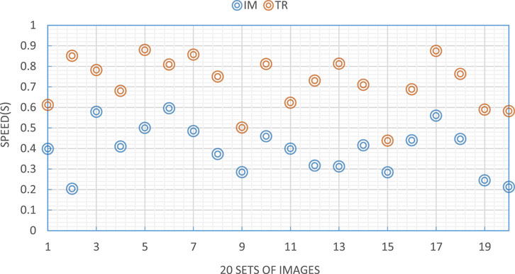
FIGURE 4. Edge detection speed.
Figure 4 reflects the edge detection speed comparison of the two algorithms. The edge detection speed of the improved IM algorithm is the same as the theoretical inference. Compared with the traditional algorithm, the edge detection speed is increased by about 81.37%, almost doubling the speed. The reason is that the Sobel operator involves 8 different pixels. The optimization method is to record 8 consecutive pixel color values in 8 variables, and each color value is represented by 16-bit data. An integer is transformed into a floating-point number, which is then transformed back into an integer. The data is likely to be larger than what can be represented by bytes, so the anti-saturation downpacking function is used when 8 int types are obtained in the final step and the result needs to be converted into a byte type.
5.2 Comparison of edge detection accuracy
The so-called accuracy is the judgment of edge points. The most direct and effective way is to use the differential operator to perform numerical differentiation on the image data to judge the edge strength and position. Most traditional differential operators use small matrix convolution, which leads to too strong directionality and poor edge detection effect in different directions. The edge detection accuracy comparison is shown in Figure 5.
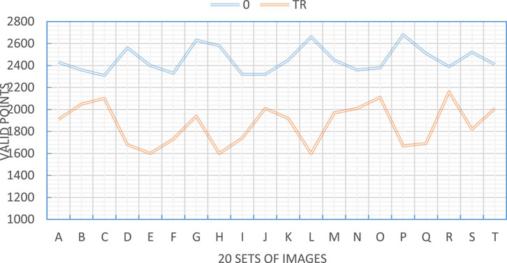
FIGURE 5. Edge detection accuracy.
Figure 5 reflects the comparison of edge detection accuracy. It can be seen that the effective point values obtained by the two algorithms are quite different, and the reflection is extreme. The larger the number of valid points, the more accurate the judgment of the edge points obtained by the algorithm can lay a good foundation for the subsequent facial contour image segmentation.
5.3 Comparison of contour segmentation effects
After edge detection is performed and edge points are obtained, further optimization is required. It is mainly reflected in the denoising of the image. The method is mainly to remove those isolated points and hanging points to facilitate the realization of contour segmentation. The value should depend on the specific conditions of the image. If not set properly, the main contours in the edge image would be destroyed. The comparison of contour segmentation effects is shown in Figure 6.
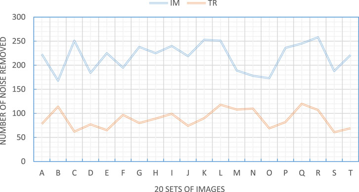
FIGURE 6. Contour segmentation effect.
Figure 6 shows the comparison of contour segmentation effects. It can be seen that the values of noise points removed by the two algorithms are very different, and the number of noise points is very different. The improved algorithm has good denoising optimization ability. After denoising, the interference factors in the image can be reduced a lot, which is beneficial to the extraction of facial features. Therefore, the optimized algorithm has a good effect on the segmentation of facial contours, but the traditional algorithm does not have a good segmentation effect.
5.4 Comparison of comprehensive effects of edge detection
The results obtained in the above experiments are weighted to generate a score, and a comparison of the comprehensive edge detection effects of the two algorithms is obtained, as shown in Figure 7.
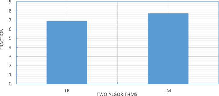
FIGURE 7. Comprehensive effect of edge detection.
The comparison of the two techniques’ complete edge detection effects is shown in Figure 7. The new approach increased the edge detection effect by roughly 12.05% when compared to the conventional edge detection algorithm. With mean or median filtering typically included before the algorithm, the upgraded algorithm typically finds edges more accurately and with less calculation time.
6 Conclusion
Image edge detection is the basic and main component of digital image processing. Generally, at the initial stage of recognition by machines, whether the correct edge detection directly affects the results of subsequent image processing. Due to the complexity of image edges and the influence of noise, there is no general algorithm for image edge detection. This paper introduced the concept of image segmentation. To solve the problems of time-consuming and poor accuracy of tissue contour generation, a contour generation algorithm was studied. In addition, this paper also selected the facial image as the research target and focused on the facial contour generation algorithm according to the grayscale characteristics of the facial image and gave the IM algorithm. The experimental results showed that using the threshold edge detection and bidirectional contour tracking algorithm to extract facial soft tissue contour can reduce the time of contour line generation and remove different tissue contours according to the threshold setting. In addition, according to the characteristics of facial contour lines, the midpoint method was used to generate auxiliary contour lines and increase the number of contour lines. The facial contour line is a non-closed curve. If a closed curve is generated, the end condition of the bidirectional contour tracking needs to be changed accordingly. There are many ways to assist contour lines, and this paper adopts different generation methods according to the contour lines’ characteristics. In the experiment, the results of edge detection speed comparison, edge detection accuracy comparison results, contour segmentation effect comparison results, and edge detection comprehensive effect comparison results were obtained. In the future, people will focus on the auxiliary contour generation method and the contour surface, hoping to find a general auxiliary contour generation algorithm and further optimize the IM algorithm.
Data availability statement
The original contributions presented in the study are included in the article/Supplementary Material, further inquiries can be directed to the corresponding author.
Author contributions
The author confirms being the sole contributor of this work and has approved it for publication.
Conflict of interest
The author declares that the research was conducted in the absence of any commercial or financial relationships that could be construed as a potential conflict of interest.
Publisher’s note
All claims expressed in this article are solely those of the authors and do not necessarily represent those of their affiliated organizations, or those of the publisher, the editors and the reviewers. Any product that may be evaluated in this article, or claim that may be made by its manufacturer, is not guaranteed or endorsed by the publisher.
References
1. Luo C, Sun X, Sun X, Song J. Improved harris corner detection algorithm based on Canny edge detection and gray difference preprocessing. J Phys Conf Ser (2021) 1971(1):012088–8. doi:10.1088/1742-6596/1971/1/012088
2. Zhang Q, Zhou X, Xu X. The supervised CNN image edge detection algorithm in scotopic vision environment. In: 2021 IEEE 9th international conference on bioinformatics and computational biology (ICBCB). IEEE (2021) 9(5):23.
3. Zhi-Bin HU, Deng CX, Shao YH. Image edge detection algorithm based on dyadic wavelet transform and improved morphology. Comput Eng Des (2020) 24(5):56–85.
4. Feng J, Yu X. Image edge detection algorithm based on adjacent scale product coefficient. In: 2020 5th international conference on electromechanical control technology and transportation (ICECTT). 2020, 8(5):126.
5. Menaka R, Janarthanan S, Deeba K. FPGA implementation of low power and high-speed image edge detection algorithm. Microprocessors and Microsystems (2020) 75(10):103053–3. doi:10.1016/j.micpro.2020.103053
6. Orujov F, Maskeliunas R, Damasevicius R, Wei W. Fuzzy-based image edge detection algorithm for blood vessel detection in retinal images. Appl Soft Comput (2020) 13(6):106452–6. doi:10.1016/j.asoc.2020.106452
7. Xu Z, Ji X, Wang M, Sun X. Edge detection algorithm of medical image based on Canny operator. J Phys Conf Ser (2021) 1955(1):012080–0. doi:10.1088/1742-6596/1955/1/012080
8. Sami R, Soltane S, Helal M. Microscopic image segmentation and morphological characterization of novel chitosan/silica nanoparticle/nisin films using antimicrobial technique for blueberry preservation. Membranes (2021) 11(5):303–4. doi:10.3390/membranes11050303
9. Suban IB, Suyoto S, Pranowo P. Medical image segmentation using a combination of lattice Boltzmann method and fuzzy clustering based on GPU CUDA parallel processing. Int J Online Biomed Eng (Ijoe) (2021) 17(11):76–7. doi:10.3991/ijoe.v17i11.24459
10. Li HA, Fan J, Zhang J, Li Z, He D, et al. Facial image segmentation based on gabor filter. Math Probl Eng (2021) 2021(6):1–7. doi:10.1155/2021/6620742
11. Rangayya V, Patil N. An enhanced segmentation technique and improved support vector machine classifier for facial image recognition. Int J Intell Comput Cybernetics (English) (2022) 15(2):302–17. doi:10.1108/ijicc-08-2021-0172
12. Yin X, Huang D, Fu Z. Segmentation-reconstruction-guided facial image de-occlusion. Comput Electr Eng (2021) 6(5):5–13. doi:10.48550/arXiv.2112.08022
13. Islam B, Mahmud F, Hossain A. A facial region segmentation based approach to recognize human emotion using fusion of HOG & LBP features and artificial neural network 2018 4th international conference on electrical engineering and information & communication technology (iCEEiCT). IEEE (2019) 89(1):15–26. doi:10.13140/RG.2.2.12027.16160
14. Zhao H, Zheng J, Wang Y, Yuan X, Li Y. Portrait style transfer using deep convolutional neural networks and facial segmentation. Comput Electr Eng (2020) 85(6):106655–155. doi:10.1016/j.compeleceng.2020.106655
15. Islam B, Mahmud F, Hossain A. A facial region segmentation based approach to recognize human emotion using fusion of HOG & LBP features and artificial neural network 2018 4th international conference on electrical engineering and information & communication technology (iCEEiCT). 2018, 15(6):565–84.
16. Bharti R, Kumar GU, Arora SK. Measurement of round shape object from the image using MATLAB. JETIR (2021) 41(5):2–6.
17. Kong L, Zou J. A novel natural image edge detection algorithm based on depth image and feature extraction. Comput Intelligence Neurosci (2017) 34(3):432–543.
18. Teng J, Zhang . A new medical image edge detection algorithm based on BC-aco. Int J Pattern Recognition Artif Intelligence (2017) 45(9):51–5. doi:10.1142/S0218001417570026
19. Cao J, Chen L, Min W, Tian Y. Implementing a parallel image edge detection algorithm based on the otsu-canny operator on the hadoop platform. Comput Intelligence Neurosci (2018) 2018(4):1–12. doi:10.1155/2018/3598284
Keywords: image edge detection algorithm, image segmentation, plastic surgery, facial contour, evaluation of edge detection algorithm
Citation: Yang C (2023) Evaluation of edge detection algorithm of frontal image of facial contour in plastic surgery. Front. Phys. 11:1108393. doi: 10.3389/fphy.2023.1108393
Received: 26 November 2022; Accepted: 03 January 2023;
Published: 25 January 2023.
Edited by:
Amrit Mukherjee, University of South Bohemia in České Budějovice, CzechiaCopyright © 2023 Yang. This is an open-access article distributed under the terms of the Creative Commons Attribution License (CC BY). The use, distribution or reproduction in other forums is permitted, provided the original author(s) and the copyright owner(s) are credited and that the original publication in this journal is cited, in accordance with accepted academic practice. No use, distribution or reproduction is permitted which does not comply with these terms.
*Correspondence: Chunxia Yang, MTYwMjEwMTI4QHN0dS5jdXouZWR1LmNu