 Andrey O. Leonov1,2,3*
 Catherine Pappas4
- 1Department of Chemistry, Faculty of Science, Hiroshima University Kagamiyama, Higashi Hiroshima, Hiroshima, Japan
- 2IFW Dresden, IFW Institute for Theoretical Solid State Physics, Dresden, Germany
- 3International Institute for Sustainability with Knotted Chiral Meta Matter, Kagamiyama, Higashi Hiroshima, Hiroshima, Japan
- 4Faculty of Applied Sciences, Delft University of Technology, Delft, Netherlands
We present a systematic study of tilted spiral states obtained theoretically within the classical Dzyaloshinskii model for magnetic states in cubic non-centrosymmetric ferromagnets. Such tilted spirals are shown to stabilize under the competing effect of cubic and exchange anisotropies inherent to cubic helimagnets. By focusing on the internal structure of these spirals and their field-driven behaviour for different aspect ratios of the anisotropy coefficients, we are able to capture the main features of the experimental findings in a bulk cubic helimagnet Cu2OSeO3 and to make a step further towards a complete quantitative model of this chiral magnet. In particular, we show that for strong anisotropy values (which experimentally correspond to low temperatures near zero) there exist an angular separation between the conical and tilted spirals, i.e., the conical spiral flips into a tilted state and immediately composes some finite angle with respect to the field direction. As the anisotropy ratio decreases, such a transition between two spiral states becomes almost continuous and corresponds to higher temperatures at the experiments. In addition, we investigate the field-driven reorientation of metastable skyrmion lattices induced by the competing anisotropies, which may be responsible for some peculiarities at the experimental phase diagrams of Cu2OSeO3.
Introduction
Cu2OSeO3 represents a unique example in the family of B20 cubic helimagnets [1, 2] exhibiting two well-defined skyrmion pockets at the temperature-magnetic field phase diagram [3, 4] (Figure 1A). The “high-temperature” (HT) pocket is commonly referred to as the A-phase: it is located at the boundary with the paramagnetic state and is also intrinsic to other cubic helimagnets such as MnSi [8, 9] and/or FeGe [10, 11]. The “low-temperature” (LT) pocket, however, arises around zero temperature and only in this particular chiral magnet. It forms exclusively for magnetic fields applied along the easy crystallographic
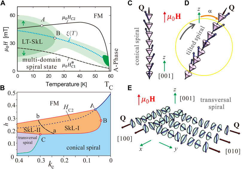
FIGURE 1. (color online) (A) Sketch of the experimental phase diagram indicating [3, 5] the extent and intensity of skyrmionic scattering after zero field cooling (ZFC) for H‖ki‖[001]. The sample was brought to each selected target temperature after cooling it through TC ≈ 59 K under zero magnetic field (i.e. under the residual magnetic field of the cryomagnet). Then, the measurements were performed upon increasing and decreasing the magnetic field and indicated hysteresis of LT-SkL formation [3, 6], i.e., skyrmionic scattering concentrates around the HC2 line when the magnetic field increases from zero to above HC2, and around the HC1 line when the magnetic field subsequently decreases from above HC2 to zero. Here, however, we superimpose both SkL stability regions, but indicate the described hysteresis by the green arrows. Deep dark green stands for the high-temperature A-phase; dark green—for the low-temperature SkL; and light green—for the weak scattering that surrounds both the LT and HT skyrmion pockets and connects them along the line ξ(T). Genuine experimental phase diagrams can be found in Refs. [3, 6], and [7]. (B) The theoretical phase diagram for kc > 0 and bea = 0 for h‖[001]. The regions of the thermodynamical stability are colored orange (skyrmions), blue (cones), and pink (transversal spirals). Both phase diagrams contain the following characteristic points: point A is an intersection point between the curve HC2 and an upper boundary of a LT-SkL pocket, which demarcates two temperature regimes and thus nucleation mechanisms of a SKL; point B is the outermost point of the LT-SkL pocket, which allows the direct ascription of the temperature from the experimental phase diagram (A) to the value of the cubic anisotropy at the theoretical phase diagram (B); point C signifies the appearance of the transversal spiral state, which was observed only in theory and thus constitutes the upper boundary for the constant of the cubic anisotropy. Both phase diagrams also contain the following characteristic lines:
Within a small pocket of A-phase, skyrmion lattice (SkL) appears spontaneously and its stability is commonly attributed to the thermal fluctuations, which “work” at relatively high temperatures [9, 13]. Moreover, the temperature versus field regime of the HT-SkL is almost isotropic for different field directions with respect to the crystal lattice. The small angle neutron pattern has a sixfold intensity for a random orientation of a sample in the A-pocket [9]. At the same time, the boundaries of the A-phase can be drastically changed by applying pressure [14], electric fields [15–18], chemical doping [19] or uniaxial strains [20, 21].
The principle of HT-SkL stabilization rests on a specific field-driven evolution of the energetic difference to SkL’s main competitor, the conical spiral [22]. The difference between the energies of the hexagonal skyrmion lattice WSkL and the conical spiral Wcone, ΔWmin = WSkL − Wcone, has minima along a curve ξ(T) exactly for those magnetic fields that stabilize the A-phase [22–24] (Figure 1A). In the following, the conical spiral is defined as a solution of the isotropic Dzyaloshinskii model (1) with the propagation direction along the magnetic field in which the magnetization rotation retains single-harmonic character, but becomes additionally distorted by different anisotropic contributions (4) (Figure 1C).
Remarkably, the same stabilization principle holds for the LT-SkL [3]. The stabilization mechanism, however, is represented by a well-known cubic anisotropy with easy
The role of cubic anisotropy in the LT-region is not limited only to the SkL stabilization, but is also manifested by many other remarkable phenomena:
(I) In particular, cubic anisotropy fixes the propagation directions of spiral states along easy anisotropy directions below the critical field Hc1 and underlies multidomain spiral states: for MnSi [8, 9] spirals propagate along the easy
The multidomain spiral state of Cu2OSeO3 below Hc1 for H‖[001] consists of spiral domains with mutually perpendicular wave vectors: one domain represents the most energetically favorable conical state (Figure 1C), and the others—metastable transversal spirals (Figure 1E), which eventually flip along the field direction. According to the theoretical predictions, the domains of transversal spirals do not reappear with the lowering field, which is also indicated by the experimental results in Ref. [12]. Thus, the field Hc1 is not shown at the theoretical phase diagram (Figure 1B) for this field direction [22, 25].
Multidomain spiral state of MnSi for the magnetic field applied along the easy anisotropy direction, H‖[111], consists of energetically degenerate oblique spirals leaning towards the field and thus deflecting from their zero-field propagation directions along the
To discern the spiral behavior at the critical fields, we will use the notion
(II) Interestingly, the spiral flips were theoretically predicted to occur also for higher fields (near Hc2) and relatively strong values of cubic anisotropy [22], but they have not been yet identified experimentally. Although the conical phase co-aligned with the field is considered to be the most favorable state above Hc1 that benefits from the Zeeman interaction, it may jump away from the field to be able to embrace a larger number of easy anisotropy axes.
For example, for
No tilted spiral states near Hc2, however, were identified theoretically for the easy cubic axes
(III) For moderate and small anisotropy values, cubic anisotropy defines the character of the phase transition between the conical and the homogeneous states at the critical field Hc2: first-order phase transition (FOPT) occurs when the magnetic field is applied along the easy anisotropy axes (in the case of Cu2OSeO3, for
(IV) Additional deviation from the generic phase diagram of cubic chiral magnets [9] is manifested in Cu2OSeO3 by the tilted spiral state (TS), which appears for the same direction of the magnetic field
Such a pronounced temperature dependence of anisotropy coefficients alongside with their complex interplay constitutes the main obstacle on the way to construct the complete quantitative model of a bulk cubic helimagnet Cu2OSeO3. In previous reports, only separate assessments of anisotropy values have been undertaken without any regard to their temperature dependence and interplay [26].
In the present manuscript, we underline distinctive features of tilted spiral states that stem from the effect of the interplaying cubic and exchange anisotropies. We discuss these results in the frame of the phenomenological theory introduced by Dzyaloshinskii in an attempt to establish a quantitative comparison between the model and the experimental results for a bulk cubic helimagnet Cu2OSeO3. In particular, we find a crossover behavior of a tilted spiral state driven by the varying ratio of anisotropy constants: i) in the case of strong cubic and exchange anisotropies, the TS directly jumps into the homogeneous state and exhibits almost no rotation; ii) for weaker anisotropies, however, the TS can smoothly rotate towards the easy axes of exchange anisotropy and even shows a reverse rotation back to the easy axes of cubic anisotropy. We argue that experimentally these two regimes are defined with respect to the critical temperature T = 18K (point A at the phase diagram in Figure 1A), which introduces an important threshold. By a systematic study of the stability and ordering of the low temperature magnetic states in Cu2OSeO3 done in Refs. [3, 5, 7] we conclude that the former case of the TS behavior is inherent for low temperatures (T = 2K) whereas the latter case allows to explain the experimental observations in the vicinity of the point A.
Additionally, we show that skyrmion states may also become oblique with respect to an applied magnetic field, which, however, occurs for the field directions
Furthermore, by comparing the experimental and theoretical phase diagrams, we are able to delineate the ranges of anisotropy constants, which may subsequently serve as a guide for future experiments. Although such theoretical undertakings require some additional fine tuning, our approach and the reasoning behind it provide a viable strategy for an in-depth and quantitative understanding of chiral magnets in view of tailoring their properties for future applications.
Phenomenological model
Within the phenomenological theory introduced by Dzyaloshinskii [27] the magnetic energy density of a bulk non-centrosymmetric ferromagnet with spatially dependent magnetization M can be written as
where A and D are coefficients of exchange and Dzyaloshinskii-Moriya interactions (DMI); H is an applied magnetic field; xi are the Cartesian components of the spatial variable. wD is composed of Lifshitz invariants
that are energy terms involving first derivatives of the magnetization with respect to the spatial coordinates. In the following, all calculations will be done for cubic helimagnets with
although the results may be applied for magnets with other symmetry classes [28] including different combinations of Lifshitz invariants.
In the forthcoming calculations, we use reduced values of the spatial variable, x = r/LD, where LD = A/D is the periodicity of the modulated states.
For the cubic helimagnet Cu2OSeO3, we supplement the isotropic energy density (1) by the exchange and cubic anisotropic contributions [26, 29],
where bea = Bea/A and kc = KcA/D2 are reduced anisotropy constants, which are in general temperature-dependent. The constants kc and bea are typically one order of magnitude smaller than the exchange stiffness A and are conventionally considered as a third level of hierarchy of energy scales following the exchange and DM interactions.
The theoretical explanation of SkL stability (Figure 1B) by the anisotropies (4) is mainly based on the effect imposed on one-dimensional spiral states. In fact, the ideal magnetization rotation in the conical state can be impaired by the easy and hard anisotropy axes for specific directions of the magnetic field. Through this mechanism, skyrmions, which are more resilient to anisotropy-induced deformations, due to their two-dimensional nature, gain stability [22].
In the following simulations, we restrict ourselves to kc > 0 with easy
The Euler-Lagrange equations derived from the energy functional (1) are non-linear partial differential equations. These equations have been solved by numerical energy minimization procedure using finite-difference discretization on grids with adjustable grid spacings and periodic boundary conditions. Components of the magnetization vector
To avoid an impediment introduced by the periodic boundary conditions, which would arise due to tilted/oblique spiral states in case of using a three-dimensional numerical grid, we perform two-dimensional simulations. For these, we write the energy density in a coordinate system
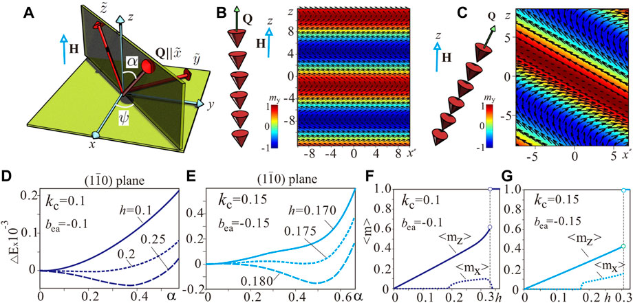
FIGURE 2. (color online) (A) Schematics of a coordinate system to address numerically two-dimensional tilted spiral states. The energy density is written in a new CS
Tilted spiral states due to the competing anisotropy interactions
For the present setup of easy
First of all, to stabilize TS in the vicinity of the critical field Hc2, the cubic anisotropy kc must overcome some threshold value (the exact value will be computed elsewhere). A relatively weak cubic anisotropy kc = 0.05 does not lead to any intermediate tilted spiral, although, according to the theoretical phase diagram in Refs. [3, 25], it is still able to stabilize a LT-SkL (Figure 1B). An increasing exchange anisotropy in this case would only switch the conical phase with α = 0 immediately into a
In the following, as instructive and representative examples, we consider two cases with kc = 0.1 (as becomes evident later, this value corresponds to higher temperatures in Cu2OSeO3) and kc = 0.15 (lower temperature range, see Sect. V. for details). Further increase of kc leads to a high-field jump from the conical into a transversal spiral, as featured by the theoretical phase diagram (see point C in Figure 1B and the pink-shaded region of the transversal spiral). Since such a limiting case was also not observed experimentally in bulk Cu2OSeO3, we may restrict ourselves to a finite range of anisotropy coefficients, which can be subsequently narrowed down for a better fitting with the experimental results.
Internal structure of a tilted spiral state for H‖[001]
Figures 2B,C show color plots of the my magnetization component for both conical and tilted spirals. The dependence of the spiral energy on the tilt angle α with Q varying in the (1
Additionally, we notice that the tilted spiral has a non-zero in-plane magnetization component, i.e., the magnetization projection onto the xy plane (Figures 2F,G), which could be discerned experimentally. However, due to the coexistence of four equivalent spiral domains canting towards four
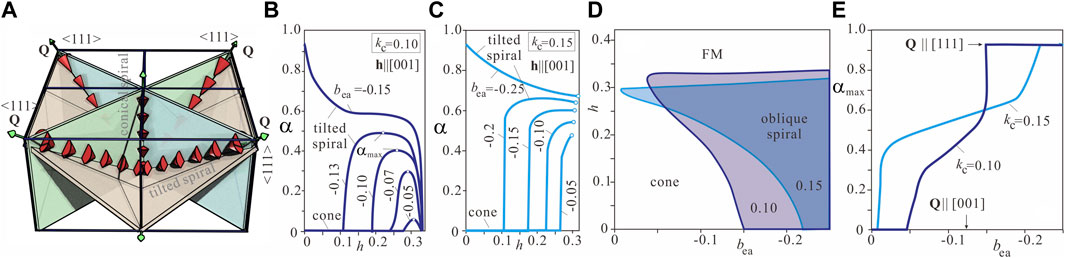
FIGURE 3. (color online) (A) Schematics showing coexisting conical and tilted spiral states. TS forms four energetically equivalent domains canting towards
Interestingly, the conical state does not “feel” the exchange anisotropy (energy of the exchange anisotropy is zero for the conical phase, since the magnetization derivatives in (4) all vanish), which would enable and underpin the experimental situation when cones and tilted spirals coexist. This coexistence is additionally facilitated by the minor energy difference mentioned before for kc = 0.1.
Remarkably, for a weaker cubic anisotropy (Figure 2F), the tilt angle α almost relaxes back to zero as for the conical phase, i.e., the value of
Field- and anisotropy-driven evolution of tilted spiral states for H‖[001]
The general behavior deduced from Figure 2 is as follows: above a critical field value, the conical spiral begins to tilt towards one of the four body diagonals, the ⟨111⟩ directions, as shown in Figure 3 and by a first-order phase transition transforms into the saturated state. Such a tilted spiral state appears when |bea| exceeds some critical value, which is slightly lower than 0.05 for kc = 0.1 and almost vanishes for kc = 0.15. For kc = 0.1, as h increases, α grows (Figure 3B), reaches its maximal value αmax and then decreases back to zero (although the tilted spiral may jump into the homogeneous state slightly below this field value as shown in Figure 2F), corresponding to a return into the conical spiral state. The corresponding maximal tilt angle, αmax, which depends on the ratio of the competing fourth-order and exchange anisotropies, is plotted in Figure 3E. As the exchange anisotropy increases above the critical value, |bea| > 0.14, the oblique spiral state with Q‖⟨111⟩ is stabilized even at zero magnetic field.
For kc = 0.15 (Figure 3C), the field-driven spiral rotation is slightly different. First of all, we notice that as h increases, the Q-vector abruptly accepts a rather high angle value (e.g., around 0.6 for bea = −0.15) and then stays almost unchanged forming a plateau up to the moment a tilted spiral undergoes the first-order phase transition with respect to the homogeneous state. Such a behaviour occurs even for small anisotropic exchange relative to the cubic anisotropy (e.g., bea = −0.05). An extended plateau is also observed on the curve αmax (bea) for the fixed kc between two critical states—the conical phase for low bea values and the
Tilted spiral state for H‖[110]
Two behavioural regimes of a tilted spiral are easily discernible for H‖[110]. Although no spiral canting towards ⟨111⟩ axes was found for kc = 0.1 (which is also the case in the experiment), it becomes well apparent for kc = 0.15 (has not been identified experimentally).
Figure 4A shows the three spiral domains with the wave vectors Q1, Q2 and Q3 at low magnetic fields and kc = 0.1. The zero-field degeneracy of the spiral states is lifted by the magnetic field, which favors the wave vectors Q1 and Q2 gradually rotating towards the field direction in the (001)-plane. Figures 4C–F show the energy density surface plots in the field range h = 0–0.07 as functions of α and ψ. The first-order phase transition between the oblique spiral states and the conical state with the wave vector Q4‖H (Figure 4B) occurs at h ≈ 0.07. The transversal metastable spiral Q3 jumps along the field at a higher field value

FIGURE 4. (color online) Spiral reorientation for H‖[110] and kc = 0.1, bea = −0.13. (A) The three spiral states in low magnetic fields. Under an applied magnetic field, the oblique spiral states with Q1 and Q2 (along the [100] and [010] directions in zero field, respectively) undergo a first-order phase transition into the conical phase with Q4‖H (B), whereas the metastable transversal spiral with the wave vector Q3‖[001] persists up to a higher magnetic field. Such a spiral reorientation is characterized by the surface plots of the energy density (C–F) depending on the angles ψ and α as defined in Figure 2A.
In the same way, the degeneracy of the zero-field spiral states is lifted by an applied magnetic field for kc = 0.15 (Figure 5). Oblique spirals with wave vectors Q1 and Q2 slowly approach the field direction (Figures 5A,C,D). At h = 0.065, however, a new energy minimum emerges, which corresponds to a tilted spiral state Q5 (Figure 5E), which becomes the global minimum of the system at h = 0.07 (Figure 5F). Notice that the saddle point (Figure 5D) appears for both values of the cubic anisotropy but only for kc = 0.15 it develops into a tilted spiral (Figure 5E). Eventually, this TS aligns with the field (Figures 5B,H).
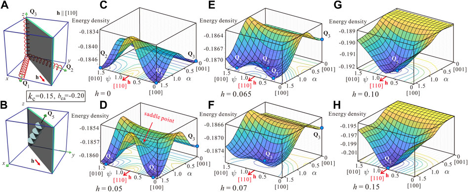
FIGURE 5. (color online) Spiral reorientation for H‖[110] and kc = 0.15, bea = −0.20. (A) The three spiral states in low magnetic fields. Under an applied magnetic field, the oblique spiral states with Q1 and Q2 (along the [100] and [010] directions in zero field, respectively) undergo a first-order phase transition into the tilted spiral state with the wave vector Q5 composing some angle with respect to the field (B), whereas the metastable transversal spiral with the wave vector Q3‖[001] persists up to a higher magnetic field. With the increasing magnetic field, the tilted spiral aligns with the [110] direction. Such a spiral reorientation, which is different from the case considered in Figure 4, is characterized by the surface plots of the energy density (C–H) plotted for several field values and allowing to capture the subtleties of the described reorientation.
Tilted skyrmion states due to the competing anisotropy interactions
In the same way as it was implemented for tilted spirals, the spatial orientation of SkLs is specified by the competing effect of easy anisotropy axes and an applied magnetic field. For example in zero magnetic field and kc > 0 (in the following, kc = 0.1), SkLs are metastable states and occupy the crystallographic {001} planes with easy axes ⟨001⟩ of the cubic anisotropy (Figures 6, 7). For h‖[001], the equilibrium position of SkL was found to be codirectional with the applied magnetic field. Consequently SkL gains stability in the vast area of the theoretical phase diagram (Figure 1B). Two energetically close SkL minima were found to occur in the transversal (001) plane. The first minimum corresponds to the easy ⟨100⟩ cubic axes pointing along the diagonals of the hexagonal SkL and along their apothems. In the second minimum, the hexagonal lattice is rotated by the angle π/4. The cores of skyrmions in both states become square shaped with the tendency either to elongate or to shorten along particular directions (see for details Ref. [25]). In the experiment [3], one can discern 12 peaks originating from these two SkL domains within the ring of scattering. For larger anisotropy values, the easy cubic axes along the diagonals may induce an elliptical instability of the SkL similar to that of isolated skyrmions [31, 32] and trigger the phase transition into the helical state. Thus only the second SkL minimum is preserved. At the phase diagram of Figure 1B, the line a − b separates the two skyrmion lattice phases. For larger values of bea, SkLs may occupy {110} planes, which include the easy axes of the exchange anisotropy ⟨111⟩. However, even in a small magnetic field, SkL planes align perpendicular to the field.
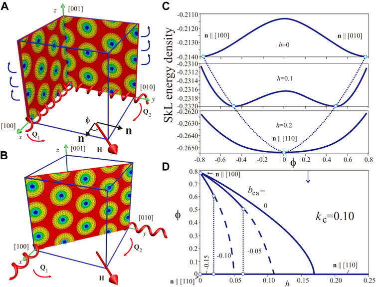
FIGURE 6. (color online) (A) Schematics of hexagonal skyrmion lattices occupying the {100} planes for the cubic anisotropy with easy ⟨001⟩ axes. In an applied magnetic field
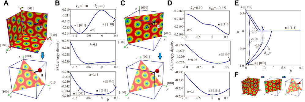
FIGURE 7. (color online) (A) Schematics of hexagonal skyrmion lattices occupying the {001} planes for the anisotropy set kc = 0.1, bea = 0 at zero field. The metastable SkLs select these planes because of the easy ⟨100⟩ axes of the cubic anisotropy. In an applied magnetic field
For other directions of the field and kc > 0, the SkL still remains a metastable solution. In an applied magnetic field h‖[110] (Figure 6A), the SkL rotates and orients perpendicular to the field, i.e., occupies the (110) plane. Whereas for bea = 0 such a rotation is smooth as shown by the energy density curves (Figure 6C), it becomes abrupt under the influence of exchange anisotropy. It is obvious that such SkLs’ jumps into the (110) plane are dictated by the easy axes ⟨111⟩ of the exchange anisotropy alongside with the Zeeman interaction. Figure 6D shows the angle ϕ between the field and the normal
For the magnetic field applied along [111] direction, the reorientation processes of LT-SkLs are more involved. Figures 7A,B show the details of SkL jumps for the “pure” effect of cubic anisotropy. SkLs, located in {001} planes, smoothly rotate towards {111} planes with increasing magnetic field. Interestingly, a SkL in the plane {110} represents a local energy minimum as shown by the first panel of Figure 7B. Two energy minima merge when the SkL aligns perpendicular to the field (third panel). For a dominating role of the exchange anisotropy (Figures 7C,D), SkLs occupy {110} planes and then gradually rotate towards {111} planes perpendicular to the field. For the chosen set of the anisotropy constants, the planes {100} do not even represent a local energy minimum (first panel in Figure 7D). For intermediate values of exchange anisotropy, however, SkLs undergo the following reorientation processes: first, they jump into a position close to {110} planes and then rotate towards {111} planes (Figure 7F). Such jumps become apparent at the field dependencies of ϕ(h) for fixed values of bea (Figure 7E).
Discussion: Quantitative model of Cu2OSeO3
To establish a quantitative phenomenological model of the bulk helimagnet Cu2OSeO3, one should determine all material constants entering Eqs. 1, 4. In this sense, hierarchically the most important Heisenberg exchange and Dzyaloshinskii-Moriya interactions may be evaluated at the atomic level, using, e.g., ab initio density functional theory (DFT) calculations. A multi-scale approach pursuing this goal is described in detail in Ref. [26] and Table 4 in the aforementioned paper gives the material constants A, D and Kc. Alternatively, the strength of the DMI together with the exchange interaction is known to govern the pitch of the spin spiral, the diameter of a single skyrmion, as well as the saturation field (Hc2) required to fully align the magnetic moments along the external field, and thus can be roughly evaluated. The obstacle to finalize the quantitative model, however, lies in the fact that anisotropic contributions with non-dimensional anisotropy coefficients kc and bea usually appear together in the magnetization processes and moreover exhibit pronounced temperature dependence. In the following, we discuss qualitatively a strategy that could be utilized to complete a quantitative model for Cu2OSeO3. We will use some behavioral patterns drawn from previous theoretical results.
First of all, we notice that the point A at the experimental phase diagram—an intersection point between the curve Hc2 and an upper boundary of a LT-SkL pocket–demarcates two temperature regimes: for lower temperatures, SkL exists above Hc2 and its nucleation is believed to be directly related to the stability region of a tilted spiral [3, 4]; for higher temperatures, SkL dissolves before the cone saturation field Hc2; at the same time, identification of the tilted spiral in this temperature interval bumps into the accuracy of experimental procedures. According to the theoretical phase diagram constructed in Ref. [25], the point A corresponds to the value
A systematic study of the stability and ordering of the low temperature magnetic states was done in Refs. [3, 5, 7]. Analysis of experimental data for low temperatures (e.g., T = 2K) prompts the following conclusions: i) an experimental value of αmax = 0.61 cannot be explained by the theoretical data for kc = 0.1, since theoretically only a smaller angle value can be achieved; on the other hand, for kc = 0.15 such an angle value is readily reached on one of the plateau-like dependencies α(h) (Figure 3D) for bea < − 0.15; ii) comparing the experimental field interval of tilted spiral existence ΔH ≈ 0.59 with Figure 3F one may estimate bea ≈ − 0.18. In any case, theoretical results for kc = 0.15 allow to qualitatively address the following experimentally observed phenomena in Ref; [7]: i) first-order phase transition with respect to the homogeneous state, which also becomes apparent in the coexistence of conical and tilted spiral states; ii) rather abrupt cone evolution into a tilted spiral state, which is identified as a blind zone, for which a tilted spiral angle does not exist (as seen in Figure 2E); iii) comparable angles and field intervals of spiral canting followed from the theory and the experiment.
Analysis of experimental data for temperatures close to the critical point A (e.g., T = 18K) can be summarized as follows: the first-order phase transition between a tilted and homogeneous states manifests itself in a rather unpronounced way; indeed, the spirals smoothly slant starting directly from the conical state and almost return back, which may be addressed by the anisotropy value kc = 0.1; an experimental ratio of two fields Hc2 for the considered two temperatures is 1.0575, which theoretically results in kc = 0.12 if one assumes kc = 0.15 for T = 2.
The value kc = 0.05 is located on the other side from the critical point A and thus corresponds to experimentally higher temperatures. The value of the exchange anisotropy must have an upper boundary, bea > − 0.08, since no oblique spirals in zero field were observed. One may remark that in this case other nucleation mechanisms should be considered to explain SkL stability [6]. Experimentally, the tilted spiral is found to persist up to above T = 35 K, which is not supported by the theoretical results with kc < 0.04. Still, due to the “flat” energy minimum for the conical state, one observes experimentally some broadening of the conical peaks without a preferable tilt direction, an effect that spans the whole conical phase and persists up to above 35 K [7]. The subsequent endeavor to construct a quantitative model for a bulk helimagnet Cu2OSeO3 must take into account experimental data for other field directions. Moreover, non-hysteretic magnetization processes with high experimental accuracy must be given a fitting preference.
Conclusion
In order to narrow down the range of anisotropy coefficients in the phenomenological model of a bulk helimagnet Cu2OSeO3 and to build its complete quantitative model, we examined the low-temperature behavior of tilted skyrmion and spiral states. By comparing the results of numerical simulations with the plentiful experimental data from our previous publications [3, 5–7] we were able to ascribe the range of the cubic anisotropy, kc = 0.15–0.10, to the temperature range T = 2–18K. The course of reasoning leading to a complete quantitative model for a bulk helimagnet Cu2OSeO3 is based on simultaneous examination of stable skyrmion and tilted-spiral states. One could not rely on the behavior of the tilted spiral alone, since it would result in some alternative parameter sets inconsistent with the behavior of LT-skyrmions. The complex reorientation processes of metastable skyrmions (Figure 6; Figure 7) are barely reflected at the experimental phase diagrams and are often hidden by the reorientation of spiral states. However, an experimental indication of tilted skyrmion states is presumably manifested by their abrupt disappearance above the
In the present manuscript, we used definitions of different modulated states (for example, transversal and conical spirals) conventional in the theoretical modeling. In the experiments, however, one would probably not specify different spiral states below the critical field Hc1 and would describe it as a multidomain spiral state. Moreover, the line Hc1 is not shown at the theoretical phase diagram in Figure 1B, since it is related to the reorientation processes of metastable transversal spirals, which, according to the theory, must not be reproduced with the decreasing magnetic field. Therefore, besides the further step to finalize the quantitative model of a bulk helimagnet Cu2OSeO3, we pursued the goal to make the terminology used in the theoretical and experimental aproaches consistent.
Data availability statement
The raw data supporting the conclusion of this article will be made available by the authors, without undue reservation.
Author contributions
AL and CP conceived of the presented idea. AL developed the theory and performed the computations. AL wrote the manuscript. All authors discussed the results and contributed to the final manuscript.
Funding
JSPS Grant-in-Aid (C) No. 21K03406 the Vrije FOM-programma “Skyrmionics”.
Acknowledgments
The authors are grateful to Marta Crisanti for useful discussions. AL. thanks U. Nitzsche for technical assistance and acknowledges JSPS Grant-in-Aid (C) No. 21K03406. CP acknowledges financial support from the Vrije FOM-programma “Skyrmionics”.
Conflict of interest
The handling editor VU declared a past co-authorshipwith the author(s) AL.
The authors declare that the research was conducted in the absence of any commercial or financial relationships that could be construed as a potential conflict of interest.
Publisher’s note
All claims expressed in this article are solely those of the authors and do not necessarily represent those of their affiliated organizations, or those of the publisher, the editors and the reviewers. Any product that may be evaluated in this article, or claim that may be made by its manufacturer, is not guaranteed or endorsed by the publisher.
References
1. Seki S, Yu XZ, Ishiwata S, Tokura Y. Observation of skyrmions in a multiferroic material. Science (2012) 336:198–201. doi:10.1126/science.1214143
2. Adams T, Chacon A, Wagner M, Bauer A, Brandl G, Pedersen B, et al. Long-wavelength helimagnetic order and skyrmion lattice phase inCu2OSeO3. Phys Rev Lett (2012) 108:237204. doi:10.1103/physrevlett.108.237204
3. Bannenberg LJ, Wilhelm H, Cubitt R, Labh A, Schmidt M, Lelievre-Berna E, et al. Multiple low-temperature skyrmionic states in a bulk chiral magnet. NPJ Quan Mater (2019) 4:11. doi:10.1038/s41535-019-0150-7
4. Chacon A, Heinen L, Halder M, Bauer A, Simeth W, Muehlbauer S, et al. Observation of two independent skyrmion phases in a chiral magnetic material. Nat Phys (2018) 14:936–41. doi:10.1038/s41567-018-0184-y
5. Qian F, Bannenberg LJ, Wilhelm H, Chaboussant G, DeBeer-Schmitt LM, Schmidt MP, et al. New magnetic phase of the chiral skyrmion material Cu2OSeO3. Sci Adv (2018) 4:eaat7323. doi:10.1126/sciadv.aat7323
6. Leonov AO, Pappas C. Topological boundaries between helical domains as a nucleation source of skyrmions in a bulk cubic helimagnet Cu2OSeO3. Phys Rev Res (2022) 4:043137. doi:10.1103/PhysRevResearch.4.043137
7. Crisanti M, Leonov AO, Cubitt R, Wilhelm H, Schmidt MP, Pappas C. Tilted spirals and low temperature skyrmions in Cu2OSeO3. Phys Rev Res (2023).
8. Ishikawa Y, Arai M. Magnetic phase diagram of MnSi near critical temperature studied by neutron small angle scattering. J Phys Soc Jpn (1984) 53:2726–33. doi:10.1143/jpsj.53.2726
9. Mühlbauer S, Binz B, Jonietz F, Pfleiderer C, Rosch A, Neubauer A, et al. Skyrmion lattice in a chiral magnet. Science (2009) 323:915–9. doi:10.1126/science.1166767
10. Uchida M, Nagaosa N, He JP, Kaneko Y, Iguchi S, Matsui Y, et al. Topological spin textures in the helimagnet FeGe. Phys Rev B (2008) 77:184402. doi:10.1103/physrevb.77.184402
11. Wilhelm H, Baenitz M, Schmidt M, Roessler UK, Leonov AA, Bogdanov AN. Precursor phenomena at the magnetic ordering of the cubic helimagnet FeGe. Phys Rev Lett (2011) 107:127203. doi:10.1103/physrevlett.107.127203
12. Halder M, Chacon A, Bauer A, Simeth W, Muehlbauer S, Berger H, et al. Thermodynamic evidence of a second skyrmion lattice phase and tilted conical phase inCu2OSeO3. Phys Rev B (2018) 98:144429. doi:10.1103/physrevb.98.144429
13. Buhrandt S, Fritz L. Skyrmion lattice phase in three-dimensional chiral magnets from Monte Carlo simulations. Phys Rev B (2013) 88:195137. doi:10.1103/physrevb.88.195137
14. Levatic I, Popcevic P, Surija V, Kruchkov A, Berger H, Magrez A, et al. Dramatic pressure-driven enhancement of bulk skyrmion stability. Sci Rep (2016) 6:21347. doi:10.1038/srep21347
15. Okamura Y, Kagawa F, Seki S, Tokura Y. Transition to and from the skyrmion lattice phase by electric fields in a magnetoelectric compound. Nat Commun (2016) 7:12669. doi:10.1038/ncomms12669
16. White JS, Prsa K, Huang P, Omrani AA, Zivkovic I, Bartkowiak M, et al. Electric-field-induced skyrmion distortion and giant lattice rotation in the magnetoelectric InsulatorCu2OSeO3. Phys Rev Lett (2014) 113:107203. doi:10.1103/physrevlett.113.107203
17. Kruchkov AJ, White JS, Bartkowiak M, Zivkovic I, Magrez A, Ronnow HM. Direct electric field control of the skyrmion phase in a magnetoelectric insulator. Sci Rep (2018) 8:10466. doi:10.1038/s41598-018-27882-4
18. White JS, Zivkovic I, Kruchkov AJ, Bartkowiak M, Magrez A, Ronnow HM. Electric-field-driven topological phase switching and skyrmion-lattice metastability in magnetoelectric Cu2OSeO3. Phys Rev Appl (2018) 10:014021. doi:10.1103/physrevapplied.10.014021
19. Wu HC, Wei TY, Chandrasekhar KD, Chen TY, Berger H, Yang HD. Unexpected observation of splitting of skyrmion phase in Zn doped Cu2OSeO3. Sci Rep (2015) 5:13579. doi:10.1038/srep13579
20. Seki S, Okamura Y, Shibata K, Takagi R, Khanh ND, Kagawa F, et al. Stabilization of magnetic skyrmions by uniaxial tensile strain. Phys Rev B (2017) 96:220404. doi:10.1103/physrevb.96.220404
21. Nakajima T, Ukleev V, Ohishi K, Oike H, Kagawa F, Seki S-i., et al. Uniaxial-stress effects on helimagnetic orders and skyrmion lattice in Cu2OSeO3. J Phys Soc Jpn (2018) 87:094709. doi:10.7566/jpsj.87.094709
22. Leonov AO, Pappas C, Kezsmarki I. Field and anisotropy driven transformations of spin spirals in cubic skyrmion hosts. Phys Rev Res (2020) 2:043386. doi:10.1103/physrevresearch.2.043386
23. Roessler UK, Leonov AA, Bogdanov AN. Skyrmionic textures in chiral magnets. J Phys Conf Ser (2010) 200:022029. doi:10.1088/1742-6596/200/2/022029
24. Leonov AO, Bogdanov AN. Crossover of skyrmion and helical modulations in noncentrosymmetric ferromagnets. New J Phys (2018) 20:043017. doi:10.1088/1367-2630/aab702
25. Leonov AO, Pappas C. Multiple skyrmionic states and oblique spirals in bulk cubic helimagnets. In: Magnetic Skyrmions and Their Applications. Editor G. Finocchio, and C. Panagopoulos (2021).
26. Janson O, Rousochatzakis I, Tsirlin AA, Belesi M, Leonov AA, Roessler UK, et al. The quantum nature of skyrmions and half-skyrmions in Cu2OSeO3. Nat Commun (2014) 5:5376. doi:10.1038/ncomms6376
27. Dzyaloshinskii IE. Theory of helicoidal structures in antiferromagnets. I. nonmetals. J Sov Phys Jetp-ussr (1964) 19:960.
28. Bogdanov AN, Yablonsky DA. Theormodynamically stable vortices in magnetically ordered crystals. Mixed state of magnetics. Zh Eksp Teor Fiz (1989) 95:178.
29. Bak P, Jensen MH. Theory of helical magnetic structures and phase transitions in MnSi and FeGe. J Phys C: Solid State Phys (1980) 13:L881–5. doi:10.1088/0022-3719/13/31/002
30. Leonov AO, Pappas C, Smalyukh II. Field-driven metamorphoses of isolated skyrmions within the conical state of cubic helimagnets. Phys Rev B (2021) 104:064432. doi:10.1103/physrevb.104.064432
31. Bogdanov A, Hubert A. The stability of vortex-like structures in uniaxial ferromagnets. J Magn Magn Mater (1994) 138195:255182–92. doi:10.1016/s0304-8853(98)01038-5
Keywords: numbers: 75.30.kz, 12.39.dc, 75.70.-i, skyrmion, chiral magnet, Cu2OSeO3, tilted spiral, low-temperature SkL
Citation: Leonov AO and Pappas C (2023) Reorientation processes of tilted skyrmion and spiral states in a bulk cubic helimagnet Cu2OSeO3. Front. Phys. 11:1105784. doi: 10.3389/fphy.2023.1105784
Received: 23 November 2022; Accepted: 11 January 2023;
Published: 02 February 2023.
Edited by:
Valery Uzdin, ITMO University, RussiaReviewed by:
Xichao Zhang, Shinshu University, JapanAlexander Petrovic, Nanyang Technological University, Singapore
Copyright © 2023 Leonov and Pappas. This is an open-access article distributed under the terms of the Creative Commons Attribution License (CC BY). The use, distribution or reproduction in other forums is permitted, provided the original author(s) and the copyright owner(s) are credited and that the original publication in this journal is cited, in accordance with accepted academic practice. No use, distribution or reproduction is permitted which does not comply with these terms.
*Correspondence: Andrey O. Leonov, bGVvbm92QGhpcm9zaGltYS11LmFjLmpw