 Taehwa Lee
 Xiaopeng Li
 Ziqi Yu
 Tsuyoshi Nomura
 Ercan M. Dede
 Hideo Iizuka
95% of researchers rate our articles as excellent or good
Learn more about the work of our research integrity team to safeguard the quality of each article we publish.
Find out more
REVIEW article
Front. Phys. , 12 October 2022
Sec. Physical Acoustics and Ultrasonics
Volume 10 - 2022 | https://doi.org/10.3389/fphy.2022.998253
This article is part of the Research Topic Advances in Acoustic/Elastic Wave Sensing for Information Processing View all 6 articles
Coupled resonance enables many intriguing physical phenomena, leading to wave control and sensing. This review discusses fundamental understanding of coupled resonance by providing detailed comparison between lumped parameter-based models including coupled mode theory (CMT) and harmonic oscillator model (HOM). While reviewing recent progress in research concerning coupled resonance, emerging research areas related to coupled resonance are discussed.
Resonance phenomena are universal, which are observed for all different types of systems based on vibrations or waves, concerning mechanical resonance, acoustic resonance, electromagnetic resonance and etc [1]. Resonance enables small periodic excitation to produce large amplitude oscillations when the excitation frequency matches with a natural frequency of the system (i.e., resonance frequency). Therefore, such resonant systems lead to many intriguing applications for wave sensing and wave control [2]. Particularly, resonant sensors having amplified responses at resonance provide high sensitivity and accuracy while effectively rejecting ambient noises. Moreover, amplified oscillation energy at resonance can be converted into other type of useful energy (e.g., electricity) [3–5]. On top of energy amplification, resonance causes abrupt phase change with respect to the resonance frequency, allowing wave interference for wave cancellation [6]. For example, resonant oscillation can counteract unwanted reflection for wave absorption [7–9].
Resonant metamaterials permit subwavelength unit structures for compact design while enabling unprecedented control of waves [10], which is based on effective parameters such as negative mass density, negative bulk modulus [11], or doubly negative mass density and bulk modulus [12, 13]. Intriguing phenomena include negative refraction [14], cloaking [15, 16] and super-lensing [17]. Also, other interesting features demonstrated with resonant structures are sound tunneling (bull’s eye) [18], and extreme impedance matching between media having large mismatch [19–21].
To increase the coverage area or maximize the interaction between wave and resonators, multiple resonators are implemented. Coupled resonances enable a rich of interesting physics such an exceptional point (EP) in non-Hermitian systems [22, 23], Fano resonance [24], electromagnetically-induced transparency (EIT) [6], and Rabi splitting [24]. These various resonance phenomena are realized depending on the coupling strength relative to the leakage (or loss) rate. The coupling strength characterizes energy exchange between the constituent resonators while the leakage (loss) rate describes the energy leakage (loss) in each resonator. To investigate the characteristics of the coupled resonators, these system parameters (coupling strength, leakage and loss rates), as lumped parameters, are used in lumped parameter-based models such as coupled mode theory (CMT) [25, 26] and harmonic oscillator model (HOM) [27, 28]. The lumped parameters used in these models permit to intuitively classify physical phenomena, although other approaches including impedance analysis [29], transfer matrix [30], and scattering matrix [31] have been widely used to characterize overall system performance.
In this review, fundamental aspects of resonance and resonant coupling are discussed in the context of lumped parameter-based models such as HOM and CMT. The lumped parameter models are thoroughly compared and the analytical formulas of the lumped parameters are summarized for simple cases. Based on such fundamental understanding, various interesting resonance phenomena are investigated, but our discussion mainly focuses on critical coupling, exceptional point, and Fano resonance. Lastly, emerging research areas concerning resonant coupling are investigated for diverse systems having non-local coupling, non-reciprocal coupling, and time-modulated interaction.
Acoustic resonators enable the localization of energy spatially and the amplification of acoustic energy at resonance. There are three representative resonators such as Helmholtz, quarter-wavelength, and membrane-type resonators, as illustrated in Figure 1A. These resonators can be modeled as a spring-mass system (i.e., harmonic oscillator). With and without intrinsic damping, they can be lossy and lossless resonators. The acoustic resonators promote flexibility in various designs by often implementing a space-coiled approach [32–34]. Also, Mie scattering resonators are constructed by using a plurality of resonators integrated into a subwavelength scatterer, exhibiting higher order resonance modes [35].
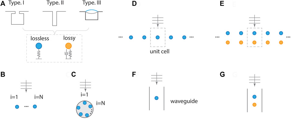
FIGURE 1. Types of coupled resonators. (A) Types of acoustic resonators (Type.I: Helmholtz, Type.II: quarter-wavelength, Type.III: membrane) with and without loss. Finite number of resonators in a linear array (B) and circular array (C). Periodic structure for a single resonator in a unit cell (D) and two resonators in a unit (E). Single resonator in a waveguide (F) and dual resonators in a waveguide (G).
Acoustic devices consisting of a finite number of resonators (e.g., linear or circular array) control incident acoustic waves or maximize interaction with acoustic waves, as shown in Figures 1B,C. Such coupled systems are manifested as superscattering [36–38] and purcell effect [39]. Moreover, periodic acoustic resonators composed of unit cells are widely employed for various scenarios (Figures 1D,E), although such a system should be truncated to a finite number of resonators in a realistic situation. Acoustic devices having periodic resonators are much larger than the wavelength such that they are treated as a system having an infinite number of resonators. The unit cell can contain single or multiple resonators. Acoustic resonators in a waveguide are highly related to duct systems, as illustrated in Figures 1F,G. These resonators in a waveguide are regarded as the same as the periodic systems (Figures 1D,E) when the width of the waveguide (period in periodic resonators) is smaller than the wavelength. Because of this similarity, the periodic systems can be characterized by testing a unit device in a waveguide (or impedance tube).
Various intriguing phenomena are enabled by coupled resonances, which can be analytically characterized by approaches using lumped parameters. These approaches include the harmonic oscillator model (HOM) and coupled-mode theory (CMT). Such lumped parameter-based approaches provide physical insights into resonance coupling between a resonator and waves or resonators. Both HOM and CMT are systematically discussed and compared. In addition, coupling rate and leakage rate, essential lumped parameters used for HOM and CMT, are characterized for a simple case, providing a tangible sense of coupled systems.
The coupled equations of motion is represented by [40].
where x is the displacement, m is the mass, k is the stiffness, Γ is the leakage rate, Δ is the intrinsic loss, K is the resonance coupling, F is the force, and the subscript 1 (2) indicates the resonator 1 (2). Here, coupling of the two resonators is described by the damping matrix having the off-diagonal term (K). Resonance coupling can be also characterized by the stiffness matrix having the off-diagonal term (stiffness coupling, Q or q = Q/m).
For e−iωt and no external forces (F1(2) = 0), eigenvalues and eigenvectors are determined from
where γ = Γ/m, δ = Δ/m, κ = K/m,
To gain insight from Eq. 2 and compare it with CMT, we assume operating frequencies close to the resonance frequencies. With the assumption of ω1 ≈ ω and ω2 ≈ ω, Eq. 2 is approximated as [41].
The 2 × 2 Hamiltonian is expressed by
where κ′ = −iκ. For two resonators having stiffness coupling (q = Q/m), κ′ is given by κ′ = q/ω1(2).
For two resonators, coupled-mode equations in the time domain are represented by [25].
where a is the mode amplitude (
With a1(2) ∝ e−iωt, the Hamiltonian is represented by
It is found that Eq. 6 is identical to Eq. 4 of HOM with the approximation. The eigenvalues of this Hamiltonian are
The two models can be used to describe any coupled resonators. From Eqs 1, 5, it is noted that HOM is expressed by the second order differential equation whereas CMT is characterized with the first time derivative. For a single resonator having no intrinsic loss (δ = 0), the equations of motion and mode amplitude for HOM and CMT are described respectively by
Here, f is given by F/m (N/kg) and f′ is set to be αf/ω0 so as to compare the two models in the same units. γ′ is given by αγ, as the leakage rate of CMT is adjusted from that of HOM. For α = 1, γ′ = γ. Figure 2 shows a comparison between the two models for two damping values γ = 0.03ω0 and 0.3ω0. For a low leakage rate of γ = 0.03ω0 and no adjustment (γ = γ′), HOS shows a significant difference from CMT, as shown in Figure 2A. With a proper adjustment of α = 0.5, CMT exhibits an excellent agreement with HOS [42]. This indicates
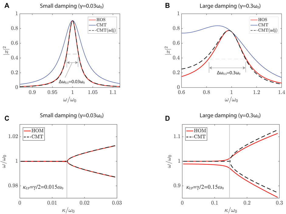
FIGURE 2. Comparison between harmonic oscillator model (HOS) and coupled-mode theory (CMT). (A) Spectral response of a single resonator for small damping (γ = 0.03ω0). (B) Large damping (γ = 0.3ω0). Eigenfrequencies of coupled resonators for γ = 0.03ω0 (C) and γ = 0.3ω0 (D). Produce (A,B) using Eqs. 7, 8 for illustration purpose. Adapt (C,D) from Ref. [42].
The two models are further compared for coupled resonators. The eigenvalues of two resonators are calculated, as the real part of the eigenvalues is plotted as a function of the coupling rate κ in Figures 2C,D. For simplicity, the coupled system consists of lossless and lossy resonators having identical resonance frequency (ω1 = ω2) and reciprocal stiffness coupling (Q1 = Q2 = Q). While CMT uses
This indicates that CMT is a good approximation for relatively low dampings. Although CMT-based results deviate from those of HOM for relatively high damping, CMT provides an physical insight into the coupled system. The lumped parameters used in CMT enable us to explicitly compare the damping rates with the coupling rate characterizing the coupling between the constituent resonators.
The radiation leakage Γ (=mγ) is related to interaction between Resonator 1 (area S1) and radiated waves by oscillating Resonator 1 (velocity U0), which is characterized by complex leakage rate given by
For 2D cases,
where λ is the wavelength and γE is the Euler’s constant of γE = 0.5332. Here,
with
Both leakage rate and coupling rate are derived from the two-dimensional dipole Rayleigh integral. As plotted in Figure 3B, the complex leakage rate is calculated as a function of the resonator width (s). The real part of the leakage rate increases with s while the imaginary part saturates and decreases for larger s. Moreover, the coupling rate is plotted as a function of d, exhibiting a decrease in |κ| with increasing d while circling the origin, as shown in Figure 3C.
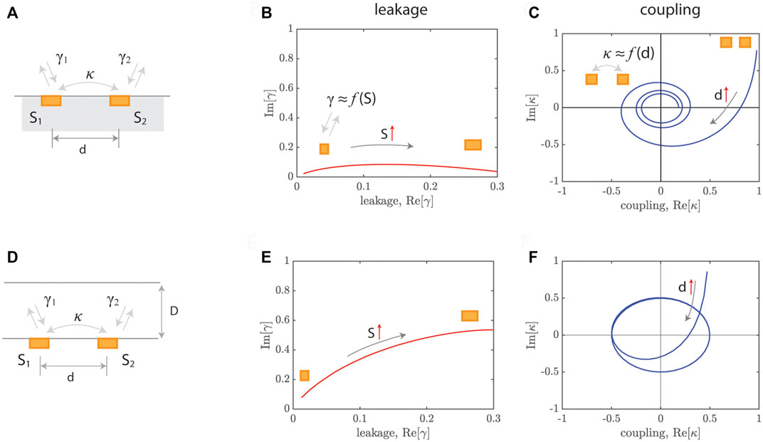
FIGURE 3. Physical understanding of leakage and coupling rate. (A) Coupled resonator in a free field. (B) Leakage rate for different sizes (S) in a free field [11]. (C) Coupling rate for different distances (d) in a free field [11]. (D) Coupled resonator in a waveguide. (E) Leakage rate in a waveguide. (F) Coupling rate in a waveguide. The gray arrows indicate the increase in s and d.
For a single resonator (width s) in a 1D waveguide (1 port) having a width of D, the complex leakage rate is given by [45].
Here, kw is the wave number and
Coupling in a single resonator occurs between the resonator and wave (surrounding), as illustrated in Figure 4A. Such coupling is characterized as leakage rate (γ). In this case, three different coupling regimes are realized depending on leakage rate (γ) relative to loss rate (δ): critical coupling, under-coupling (γ < δ), and over-coupling (γ > δ), as summarized in Figure 4C. The critical coupling states that the leakage rate (γ) should be balanced with the intrinsic loss (δ) [46]:
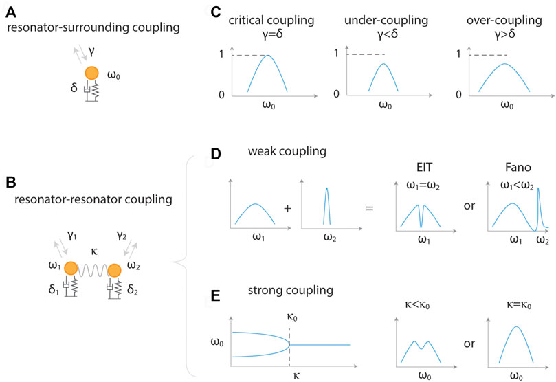
FIGURE 4. Coupling in resonator systems. (A) Coupling between a resonator and environment. (B) Coupling between two resonators. (C) Different coupling regimes in (A), exhibiting critical coupling (γ = δ), under-coupling (γ < δ), and over-coupling (γ > δ). (D) Weak coupling regimes in (B) (κ < |γ1 + δ1| or κ < |γ2 + δ2|) showing EIT and Fano resonance. (E) Strong coupling regimes in (B) (κ > |γ1 + δ1| and κ > |γ2 + δ2|) demonstrating exceptional points.
This condition leads to perfect absorption, which can be readily proved from CMT. The mode amplitude of a single resonator is given by
Thus, the absorption (A) is expressed by
The critical coupling condition is discussed for various cases, as shown in Figure 5. For a single subwavelength resonator in a free field (Figures 5A,B), absorption is characterized by absorption cross section (σabs) defined by the absorbed power (Pabs) relative to the incident power (Pinc), i.e.,
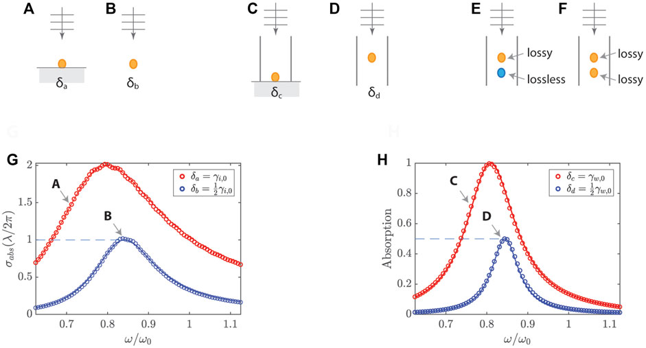
FIGURE 5. Critical coupling for acoustic absorption. Single resonators in a free field with a backing surface (A) and free field (B). Single resonators in waveguides for one-port (C) and two-port systems (D). Dual resonators in a waveguide for loss/lossless (E) and loss/loss (F). (G) Absorption cross section spectra for (A) and (B). (H) Absorption spectra for (C) and (D). Adapt (G) from Ref. [36]; Adapt (H) from Ref. [47].
The critical coupling enables perfect absorption for a single resonator placed in the middle of a waveguide, as illustrated in Figures 5C,D. The one-port system (Figure 5C) shows unity absorption for δc = γw,0 with
The critical coupling condition is further discussed for two resonators in two-port systems, as illustrated in Figures 5E,F. When the two resonators have asymmetric losses (i.e., lossy upstream and lossless downstream resonators), the perfect absorption and critical coupling condition are similar to those of the single resonator in a one-port system (Figure 5C). This is because the downstream resonator functions as a reflector. On the other hand, two resonators having symmetric losses show perfect absorption when the waveguide width (or period) is close to the wavelength at resonance (λ0) and the distance between the resonators is much smaller than the wavelength.
For perfect resonant absorption, the critical coupling is widely used and it is readily realized by either adjusting leakage rate or intrinsic loss [30, 49, 50]. The leakage rate is geometrically controlled by choosing a waveguide of specific width or adjusting the effective size of a resonator. Similarly, the intrinsic loss of a resonator is engineered by changing geometrical parameters for thermal viscous losses or introducing lossy materials. In Figure 6A, the single Helmholtz resonator is attached to the side of the waveguide, fulfilling the critical coupling condition, which is confirmed in a complex frequency map (Figure 6B) [49]. The perfect absorption is enabled for various configurations, as shown in Figure 6C. The results indicate that regardless of the intrinsic losses, the critical coupling condition can be satisfied by carefully adjusting the physical parameters.
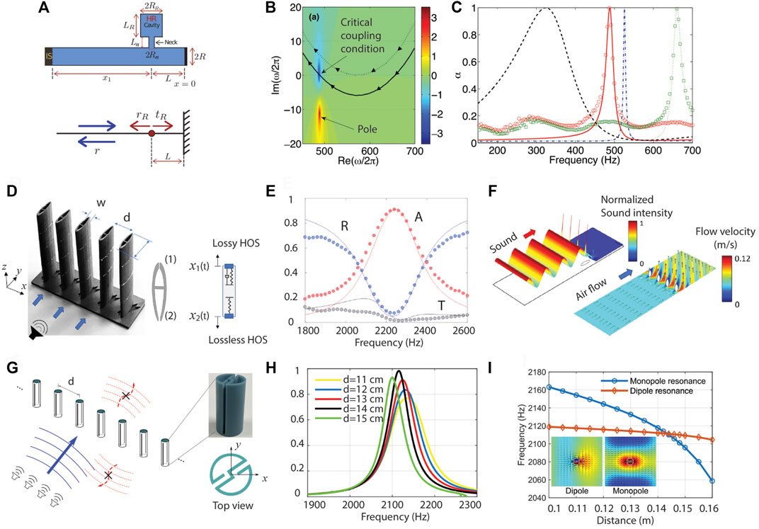
FIGURE 6. Critical coupling for perfect sound absorption. (A) Coupled resonator in a one-port system. (B) Critical coupling conditon. (C) Perfect sound absorption of the resonator system (A). (D) Coupled resonators composed of loss/lossless in a two-port system. (E) Corresponding absorption spectra. (F) Sound absorption and fluid-flow (ventilation) control. (G) Coupled resonators consisting of loss/loss in two-port system. (H) Absorption spectra for different period. (I) Monopole and dipole resonance enabled by a certain period (d = 0.14 m). Reprint (A–C) from Ref. [49]; (D–F) from Ref. [47]; (G–I) from Ref. [51].
Perfect absorption was realized in two-port systems using resonance degeneracy with coupled resonators in a unit cell [28], as illustrated in Figures 5E,F. These absorbers are so called ventilated sparse absorbers since fluid flow is permitted while noises are absorbed [47, 52, 53]. In Figure 6D, a fish-shape unit device consists of a lossy upstream resonator and a lossless downstream resonator [47]. For such a loss asymmetry, the opening (or neck) of the downstream is larger for reducing viscous loss, while its cavity size is increased to maintain its resonance frequency same as that of the upstream resonator. Under the critical coupling condition, the near perfect absorption of the fish-shaped device was experimentally characterized, as shown in Figure 6E. Also, the device having a streamline body enables the control of fluid flow directions while minimizing the flow resistance, as illustrated in Figure 6F.
Two identical resonators having symmetric losses in a two port system show perfect absorption for a relatively large period (or space between unit devices). Such an interesting characteristic was confirmed using coupled resonators, as illustrated in Figure 6G [51]. Depending on the distance between the unit devices (i.e., period), the absorption peak values are varied as shown in Figure 6H. The optimized distance was found to be d = 14 cm, which corresponds to approximately 0.85λ0. This specific distance for perfection absorption results in the degeneracy of monopole and dipole resonances in Figure 6I.
A finite number of coupled resonators exhibit intriguing wave scattering and absorption characteristics, as summarized in Figure 7. Coupled resonators of asymmetric intrinsic losses show different absorption cross section spectra for opposite incidences [44], as shown in Figures 7A,B. In the referred work, the opposite incidences cause a difference in vibration phases, thus promoting asymmetric absorption by increasing the response of the lossy resonator for a specific incidence angle. This concept can be extended to an array system [55].
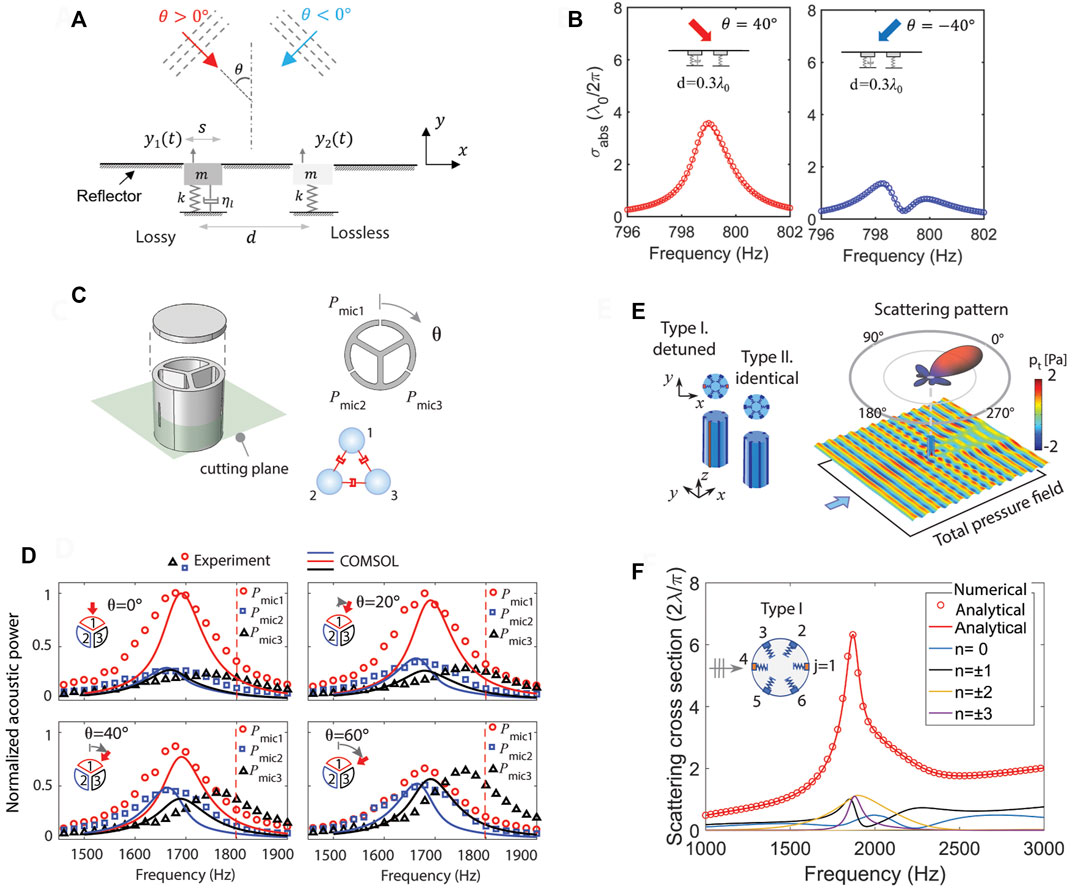
FIGURE 7. Coupled resonators in open field. (A) Asymmetric absorption scattering. (B) Corresponding absorption scattering cross section spectra. (C) Coupled resonators-based acoustic direction sensor. (D) Acoustic power spectra in each resonator of the direction sensor. (E) Coupled resonators for acoustic superscattering. (F) Scattering cross section spectra of the superscatter. Reprint (A,B) from Ref. [44], (C,D) from Ref. [54], (E,F) from Ref. [36].
From the directional characteristics of the coupled resonators (Figure 7A), coupled resonators can be used for sensing the direction of incoming waves [54], as shown in Figure 7C. In the study, three resonators integrated to the cylindrical scatterer are capable of amplifying the acoustic waves depending on the incident angle. In Figure 7D, the response of each resonator is varied for different incident angles. This subwavelength direction sensor is advantageous over conventional direction sensors relying on bulky systems of multiple detectors for considerable differences in wave phases. This conception was originally proposed in optics as angle-sensing, bio-inspired photodetectors [56]. Also, such directional resonance coupling is demonstrated in magnetic wave direction sensing [57].
Multiple resonators within a subwavelength scatterer induce relatively strong coupling, which increases interaction between an incident wave and the resonators [36–38]. Such strong wave interaction is manifested as superscattering, as illustrated in Figure 7E. The scattering cross section of the scatterer is extremely high (approximately six times greater than that of a single resonator), when a large number of scattering channels are excited, as observed in Figure 7F. Due to reciprocal physical properties, the superscattering behavior is closely related to a super-emitter consisting of a source surrounded by resonators, which is demonstrated as a purcell effect [39].
Coupling between resonators is illustrated in Figure 4B. Various coupling phenomena are observed depending on coupling rate relative to leakage (or loss) rate, as shown in Figures 4D,E. Exceptional point states that coupling strength between the coupled resonators is balanced with the loss difference, leading to the eigenvalue coalescence. From Eq. 6, the eigenfrequencies of the coupled resonators are given by
where Δω = ω2 − ω1 and Δ(γ + δ) = γ2 + δ2 − (γ1 + δ1). Here, the two eigenvalues coalesce if the square-root term in Eq. 14 becomes zero. For a real and reciprocal coupling (κ1 = κ2 = κ), the EP occurs when Δω = 0 and 2κ = |Δ(γ + δ)|. From Eq. 14, assuming a purely imaginary coupling
To consider a more general case where the coupling strength (κ) is a complex value, EP conditions are characterized in two cavity resonators coupled via a thin channel, as illustrated in Figure 8A. The complex coupling strength (κ) is defined by a length of the channel (l), which is given by κ = κ0exp (iθ) = κ0 [cos(θ) + i sin(θ)] with
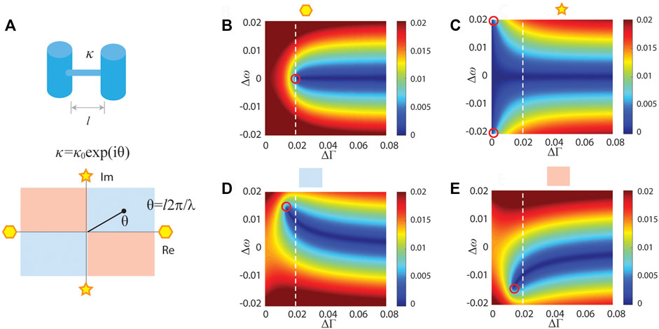
FIGURE 8. Exceptional point in coupled resonators. (A) Coupled cavity resonators having the complex coupling strength (κ) and κ = κ0exp (iθ). (B) Square-root term for θ = π/4 + nπ. The red circle indicates the condition (ΔΓ and Δω) for the zero square-root term. (C) Pure imaginary coupling (θ = π/2 + nπ). (D) π/4 + nπ (E) 3π/4 + nπ.
Non-Hermitian physics and multiple exceptional points are systematically studied for two-state and higher-order systems, as shown in Figure 9A [23]. In a two-state system consisting of two cavity resonators coupled through a coupling tube, the pressure of a single acoustic cavity is characterized by increasing additional loss at the other acoustic cavity. By retrieving the eigenmodes from the experimental data, it is observed that the two eigenmodes coalesce at an EP when ΔΓ = 2|κ| in Figure 9B. Beyond single EP, interesting EP phenomena are enabled at a higher dimension such as a four-state systems (Figure 9C), where multiple EPs are realized for higher-order EP-related physics.
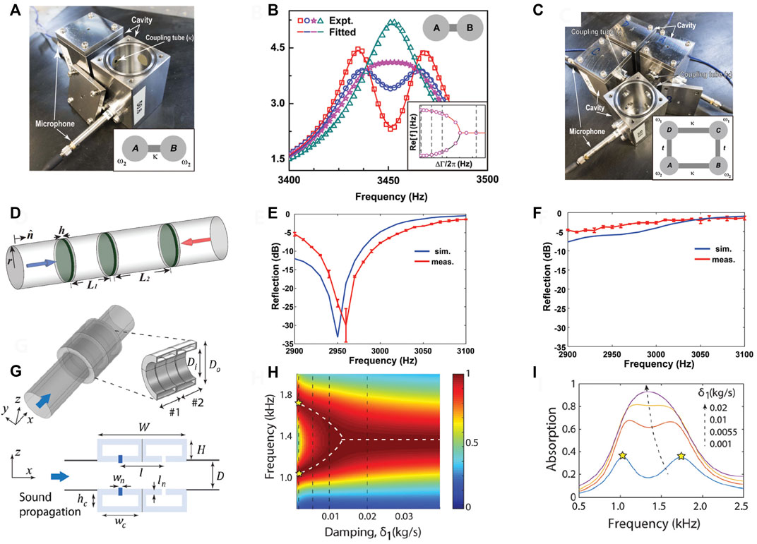
FIGURE 9. Exceptional point in coupled resonator system. (A) Exceptional point of two cavity resonators in a closed system. (B) acoustic spectra for varying loss. (C) Higher-order exceptional point. (D) Exceptional point for unidirectional zero reflection. Reflection spectra from one incidence (E) and the opposite direction (F). (G) EP-based duct silencer for perfect absorption. (H) Absorption spectra for different damping exhibiting absorption peak collapse. (I) Representative absorption spectra. Reprint (A–C) from Ref. [23]; (D–F) from Ref. [59]; (G–I) from Ref. [41].
EPs are observed in a bianisotropic system comprising of three thin plates and two lossy regions in between [59], as illustrated in Figure 9D. Asymmetry is introduced to the system by having different lengths of the lossy regions. With such geometry asymmetry and unbalanced loss, this work demonstrates unidirectional zero reflection for the forward direction in Figure 9E while the high reflection is observed for the backward direction in Figure 9F. The EP condition is confirmed by a degenerate non-Hermitian scattering matrix.
In addition to the unidirectional wave control, EP enables perfect sound absorption of coupled resonators in a duct [41]. The perfect absorption in coupled resonators is realized when both the critical coupling and EP conditions are simultaneously satisfied. In this work, asymmetric loss is implemented into the system, as the upstream resonator has a relatively large loss compared to the downstream resonator. When two resonators are strongly coupled, two absorption peaks of small amplitudes are observed. These two peaks merge into one peak at a EP, as shown in Figures 9H,I. In this two-port system, conditions for critical coupling (δ = γ) and EP (2κ = |Δ(γ + δ)| = δ) are simultaneously met for perfect absorption. For two resonators in a one-port system, the EP condition is not required as long as each resonator meets the critical coupling condition. However, resonance degeneracy is essential to perfect absorption in two-port systems. In this regard, the EP condition is a good indicator to see if resonance degeneracy is achieved. Similarly, EP-based elastic wave absorption is reported in Ref. [60].
A Fano resonance, exhibiting an asymmetric line-shape, occurs when a discrete localized state is coupled to a continuum of states [24]. The asymmetric line-shape is produced by interference between a background (continuum state) and a resonant scattering process. The background scattering amplitude typically varies slowly with frequency whereas the resonant scattering amplitude changes both in magnitude and phase quickly. The response by the Fano resonance characterizes absorption, transmission and scattering. The sharp resonance peak enabled by the Fano resonance is useful for sensing applications. For the coupled resonators, the Fano resonance is observed in the weak-coupling regime: |κ|≪|γ1 + δ1| or |κ|≪|γ2 + δ2|. For f1 ≠ 0, f2 = 0 and a two-oscillator model in the weak-coupling regime, the amplitude of the driven oscillator 1 can be presented in the form [24]:
where
is the dimensionless frequency. The Fano parameter q determines the spectral shape and depends on the spectra detuning of the oscillators ω2 − ω1. q = cotδ, where δ is the phase of the response function
For such a week coupling regime, when two resonators have the identical resonance frequency ω1 = ω2 so that Fano resonance (i.e., interference) happens for q = 0, the high transmission occurs at ω1 = ω2. This spectral lineshape is known as electromagnetically induced transparency (EIT), as illustrated in Figure 4D. Of course, two resonators having similar bandwidths may show EIT for ω1 ≠ ω2 by demonstrating destructive interference and consequently high transmission at a frequency between ω1 and ω2.
Figure 10 shows different cases demonstrating Fano resonances. First, Fano resonances are observed for non-resonant background scattering in free field (Figure 10A) and waveguide (Figure 10B). The reduced scattering is seen for a circular scatterer having a Helmholtz resonator in Figure 10E. The non-resonant background scattering (corresponding to the circular scatterer without resonance) is represented as the dashed line. Similarly, non-resonant background scattering is introduced in a waveguide, as shown in Figure 10F. The near-zero reflection is observed at a frequency before the resonance. Also, the background scattering can be induced by a resonator in a waveguide, as long as the response of the resonator slowly varies. This case is illustrated in Figures 10C,D for different configurations. These dual-resonator systems are slightly different in terms of excitation. In Figure 10C, only one of the resonators is excited whereas both resonators are excited in Figure 10D. Resulting reflection spectra for both systems are similar, promoting zero reflection between two resonance frequencies.
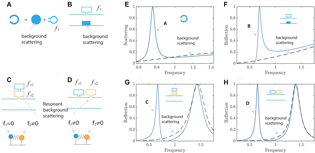
FIGURE 10. Different types of Fano resonances. (A) Resonant scatterer having non-resonant background scattering and resonant scattering (fr) in a free field.(B) Resonator and non-resonant scatterer in a waveguide. (C) Dual resonators in a waveguide having a resonant background scattering (fr2) and a narrow band resonant scattering (fr1). Only the resonator having background scattering is excited (f1 = 0 and f2 ≠ 0). (D) Dual resonators stacked along the waveguide. Both resonators are excited (f1 ≠ 0 and f2 ≠ 0). (E) Scattering spectrum with a background scattering spectrum (dashed line) in a resonant scatterer (A). (F) Reflection spectra of the system (B). (G) Reflection spectra of the system (C). (H) Reflection spectra of the system (D).
Fano resonance is implemented in a waveguide for reducing transmission, as shown in Figure 11A and B [61, 62]. Interference for Fano resonance occurs between non-resonant background scattering and resonant scattering, as illustrated in Figure 10B. Here, non-resonant background scattering is introduced by the central part (highlighted by the yellow region) in Figure 11A, exhibiting reflection due to the area reduction. The resonant reflection enabled by the helical part shows dual peaks at 340 Hz and 695 Hz (dashed green line) in Figure 11B. This concept was first proposed in Ref. [65], where a relatively narrow-band Fano resonance is demonstrated. The helical resonators are a space-coiled version of an open-pipe resonator, which is open at both ends. The resonant frequencies of an open-pipe resonator are
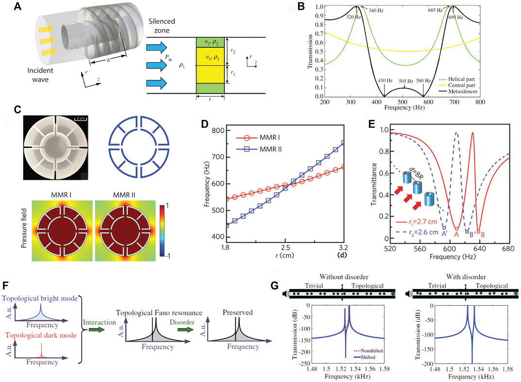
FIGURE 11. Fano resonance in coupled resonators. (A) Fano resonance-based Duct silencer. (B) Transmission spectra of each contribution. (C) Dual Fano resonance by Mie resonators supporting two-type monopole resonances (D) and (E) corresponding transmission spectra. (F) Topological Fano resonance. (G) Robust Fano resonance with and without disorder. Reprint (A,B) from Ref. [61]; (C–E) from Ref. [62]; (F,G) from Ref. [63].
Dual-band Fano resonances are realized by artificial Mie resonances [62], as illustrated in Figure 11C. Two types of monopolar Mie resonances are observed, which are controlled by adjusting the size, as shown in Figure 11D. This exhibits two resonance peaks spaced apart, each promoting a Fano resonance in Figure 11E. Unlike the broadband Fano resonance, dual-band Fano resonances are induced around the resonant frequencies, as each resonant mode leads to destructive interference with the background scattering.
Although Fano resonance has shown promise in sensing applications, it is difficult to construct such a system due to geometrical imperfection. To address this challenge, Fano resonance is combined with 1D topological insulator, demonstrating robust topological Fano resonance [63], as illustrated in Figure 11F. Such an interesting feature was experimentally validated, as shown in Figure 11G.
Fano resonance between resonators also demonstrates asymmetrical spectral line-shape for reflection, as illustrated in Figures 10G,H. For transmission, such Fano resonance between resonators are typically discussed as acoustically induced transparency (AIT) [67–69], where two resonators have detuning and weak coupling interact, supporting Fano resonance. In other words, both AIT and Fano resonance share the same physical mechanism. When one resonator has much wider bandwidth and function as background scattering, the observation can be categorized as Fano resonance. On the other hand, AIT has two resonators with comparable bandwidth.
Traditional coupling phenomena have been further considered with emerging physical concepts such as time modulation of physical properties, non-local interaction (long-range coupling), and non-reciprocity, as shown in Figure 12. As illustrated in Figure 12A, the 3D metamaterial having non-local effects is based on the long-range coupling being stronger than the nearest-neighbor coupling [70]. In this case, the dispersion relation exhibits a sign change of the slopes (group velocity, vg = ∂ω/∂kz) for different wavenumbers (A, B, and C) and the same frequency, as seen in Figure 12B. This negative slope (wavenumber B) implies that the energy flow is reversed, while the phase velocity (vph = ω/kz) remains positive. The theoretical finding was validated with experimental observation [72, 73]. Such Roton-like characteristics observed in correlated quantum superfuids are realized in the classical system relying on coupled resonators, which can serve as simple tabletop experiments for condensed matter physics and quantum mechanics [75].
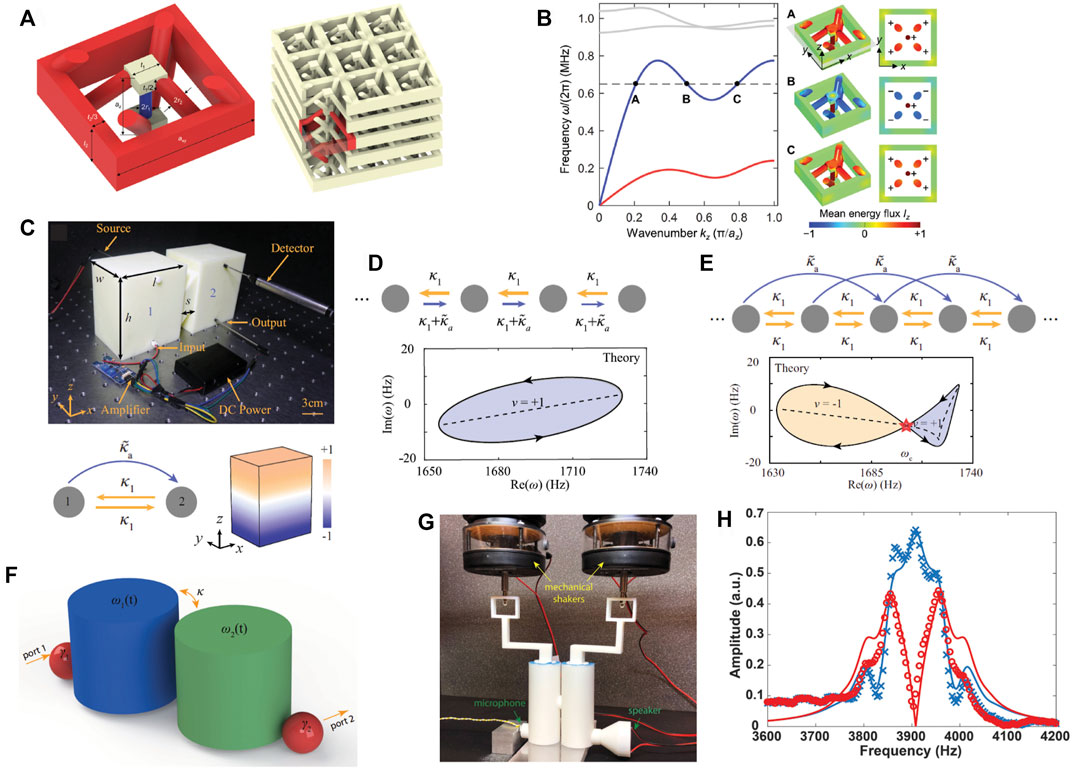
FIGURE 12. Emerging research using coupled resonators. (A) Long-range coupling in coupled resonators. (B) Non-local oddities by the long-range coupling. (C) Asymmetric resonant coupling in cavity resonators. (D) Winding number in nonreciprocal nearest-neighbor coupling. (E) nonreciprocal long-range coupling. (F) Time modulated resonance coupling. (G) Resonance modulation. (H) Nonreciprocal wave transmission for the forward (blue) and backward (red) directions. Reprint (A,B) from Ref. [70]; (C–E) from Ref. [71]; (F–H) from Ref. [72].
Resonance coupling is controlled by implementing an additional coupling through an external circuit, enabling non-reciprocal resonance coupling [71], as shown in Figure 12C. Such non-reciprocal coupling, exhibiting the single-loop winding of the complex energy spectrum (Figure 12D), results in a non-Hermitian skin effect (NHSE) that shows the wave localization on one of the boundaries depending on the winding number. This system further demonstrates non-reciprocal long-range coupling, leading to twisted winding topology with two oppositely oriented loops (i.e., different signs of the winding number) in Figure 12E.
Time-modulated resonators enable interesting coupling behaviors which cannot be observed in traditional resonators [72]. The energy exchange between coupled resonators is regulated by implementing modulated resonance frequencies with proper spatial phase bias, as illustrated in Figure 12F. In Figure 12G, the resonance frequency of each resonator is modulated by the cavity volume change induced by the vibrating upper disk, which is actuated by a mechanical shaker. This coupled system with dynamic modulation demonstrates nonreciprocal energy transmission, as shown in Figure 12H (red: backward, blue: forward).
Coupled resonators are considered as a fundamental building block, enabling effective wave control and sensing. Among several theoretical frameworks characterizing coupled resonance phenomena, the lumped parameter-based models have many advantages by reducing the complicate description of physical systems to a few key physical parameters capturing essential physical characteristics. First, such models are simple but very intuitive by permitting explicit description of coupling strength, which is one of critical parameters dictating interaction between constituent resonators. Also, the explicit coupling strength can be compared with other key parameters such as the leakage rate and intrinsic loss, consequently allowing estimation of the overall system characteristics. After thorough comparison between two representative lumped parameter-based models, various coupled resonance phenomena are discussed, including critical coupling, Fano resonance, and exceptional point.
While having many advantages, the lumped parameter-based models also have disadvantages, requiring ardours extraction of constituent lumped parameters through separate simulation or parameter fitting. Since other physical parameters describing the systems are lumped to a few representative parameters, knowledge of how these lumped parameters are correlated to other physical parameters is often more important. In this sense, lumped parameter-based models are complementary with other theoretical frameworks without using lumped parameters.
For perfect absorption, one can design and optimize an absorber without realizing the critical coupling. Instead, if the absorber exhibits perfect absorption, one claims that the critical coupling must be satisfied. As long as the leakage rate is balanced with the intrinsic loss, the perfect absorption is enabled by multiple optimum solutions. By increasing the leakage rate and intrinsic loss simultaneously, broadband perfect absorbers are constructed [46]. Interaction of resonators with incident waves in open field leads to intriguing physical features. Finite number of resonators are simple, but demonstrating rich coupling behaviors such as directionality and scattering. Also, physical insights into resonant coupling are gained and can be extended to periodic arrays.
For wave sensing, Fano resonance is a great choice due to its sharp spectral line shape, exhibiting high sensing sensitivity. However, such high sensitivity realized in Fano resonance poses challenges in constructing Fano resonance-based sensing systems. Fano resonance in combination with Topological insulators greatly improve system robustness [63]. Moreover, systems with exceptional points have been only implemented for acoustic resonance degeneracy, and they can be a nice sensing platform as proposed in optics. Sensing sensitivity can be improved by implementing higher order exceptional points.
As discussed by introducing the emerging research, metamaterial research based on coupled resonance continues to evolve in a way that enables design of exotic coupling between resonators or resonant modes without any restrictions imposed by the physical distance and reciprocity. For example, resonance coupling can be established through a closed-loop control system, which is composed of a sensor, actuator, and autonomous controllers preprogrammed to define a transfer function between the sensor and actuator [76]. In this example, the mechanical lattice demonstrates non-Newtonian topological insulation with nonreciprocal coupling and next nearest-neighbor coupling. This approach implies that the autonomous controllers can be programmed to support any arbitrary coupling and the electric wires used for the closed-loop control system permit any long-range coupling.
Recently, research on optical metamaterials has advanced to implement synthetic dimensions [77, 78], which enable extension of the geometric dimensionality of a photonic structure such that one-dimensional structures with a synthetic dimension can exhibit two-dimensional-like physical features. For instance, a dynamically modulated ring resonator functions as a one-dimensional lattice in the synthetic frequency dimension [79]. Such optical concepts based on synthetic dimensions are useful in acoustic resonators. With a few number of acoustic resonators, exotic coupling between resonance modes can be realized as it is demonstrated in two coupled ring resonators [80].
Although coupled resonators are a promising platform for wave sensing, resonance-based sensing approaches perturb their measurement and create considerable wave scattering [81]. To avoid such an issue while benefiting from resonance, one can consider a non-resonant sensor connected to electrical resonance, which is so-called virtual acoustic resonance. Therefore, many existing resonant systems can be translated into systems composed of virtual acoustic resonators.
All authors listed have made a substantial, direct, and intellectual contribution to the work and approved it for publication.
TL, XL, ZY, TN, ED and HI were employed by Toyota Motor North America.
All claims expressed in this article are solely those of the authors and do not necessarily represent those of their affiliated organizations, or those of the publisher, the editors and the reviewers. Any product that may be evaluated in this article, or claim that may be made by its manufacturer, is not guaranteed or endorsed by the publisher.
2. Homola J, Yee SS, Gauglitz G. Surface plasmon resonance sensors: Review. Sensors actuators B: Chem (1999) 54:3–15. doi:10.1016/s0925-4005(98)00321-9
3. Liu F, Phipps A, Horowitz S, Ngo K, Cattafesta L, Nishida T, et al. Acoustic energy harvesting using an electromechanical Helmholtz resonator. The J Acoust Soc America (2008) 123:1983–90. doi:10.1121/1.2839000
4. Tang L, Yang Y, Soh CK. Toward broadband vibration-based energy harvesting. J Intell Mater Syst structures (2010) 21:1867–97. doi:10.1177/1045389x10390249
5. Li B, You JH, Kim YJ. Low frequency acoustic energy harvesting using pzt piezoelectric plates in a straight tube resonator. Smart Mater Struct (2013) 22:055013. doi:10.1088/0964-1726/22/5/055013
6. Fleischhauer M, Imamoglu A, Marangos JP. Electromagnetically induced transparency: Optics in coherent media. Rev Mod Phys (2005) 77:633–73. doi:10.1103/revmodphys.77.633
7. Mei J, Ma G, Yang M, Yang Z, Wen W, Sheng P. Dark acoustic metamaterials as super absorbers for low-frequency sound. Nat Commun (2012) 3:756–7. doi:10.1038/ncomms1758
8. Ma G, Yang M, Xiao S, Yang Z, Sheng P. Acoustic metasurface with hybrid resonances. Nat Mater (2014) 13:873–8. doi:10.1038/nmat3994
9. Liu K, Liu J. The damped dynamic vibration absorbers: Revisited and new result. J sound vibration (2005) 284:1181–9. doi:10.1016/j.jsv.2004.08.002
10. Cummer SA, Christensen J, Alù A. Controlling sound with acoustic metamaterials. Nat Rev Mater (2016) 1:16001–13. doi:10.1038/natrevmats.2016.1
11. Lee SH, Park CM, Seo YM, Wang ZG, Kim CK. Acoustic metamaterial with negative modulus. J Phys : Condens Matter (2009) 21:175704. doi:10.1088/0953-8984/21/17/175704
12. Ma G, Sheng P. Acoustic metamaterials: From local resonances to broad horizons. Sci Adv (2016) 2:e1501595. doi:10.1126/sciadv.1501595
13. Li J, Chan CT. Double-negative acoustic metamaterial. Phys Rev E (2004) 70:055602. doi:10.1103/physreve.70.055602
14. Kaina N, Lemoult F, Fink M, Lerosey G. Negative refractive index and acoustic superlens from multiple scattering in single negative metamaterials. Nature (2015) 525:77–81. doi:10.1038/nature14678
15. Zhang S, Xia C, Fang N. Broadband acoustic cloak for ultrasound waves. Phys Rev Lett (2011) 106:024301. doi:10.1103/physrevlett.106.024301
16. Popa BI, Zigoneanu L, Cummer SA. Experimental acoustic ground cloak in air. Phys Rev Lett (2011) 106:253901. doi:10.1103/physrevlett.106.253901
17. Zhu J, Christensen J, Jung J, Martin-Moreno L, Yin X, Fok L, et al. A holey-structured metamaterial for acoustic deep-subwavelength imaging. Nat Phys (2011) 7:52–5. doi:10.1038/nphys1804
18. Mei J, Hou B, Ke M, Peng S, Jia H, Liu Z, et al. Acoustic wave transmission through a bull’s eye structure. Appl Phys Lett (2008) 92:124106. doi:10.1063/1.2903704
19. Bok E, Park JJ, Choi H, Han CK, Wright OB, Lee SH. Metasurface for water-to-air sound transmission. Phys Rev Lett (2018) 120:044302. doi:10.1103/physrevlett.120.044302
20. Cai Z, Zhao S, Huang Z, Li Z, Su M, Zhang Z, et al. Soft acoustic metamaterials: Bubble architectures for locally resonant acoustic metamaterials (adv. Funct. Mater. 51/2019). Adv Funct Mater (2019) 29:1970346. doi:10.1002/adfm.201970346
21. Lee T, Iizuka H. Sound propagation across the air/water interface by a critically coupled resonant bubble. Phys Rev B (2020) 102:104105. doi:10.1103/physrevb.102.104105
22. Bender CM, Boettcher S. Real spectra in non-hermitian Hamiltonians HavingPTSymmetry. Phys Rev Lett (1998) 80:5243–6. doi:10.1103/physrevlett.80.5243
23. Ding K, Ma G, Xiao M, Zhang Z, Chan CT. Emergence, coalescence, and topological properties of multiple exceptional points and their experimental realization. Phys Rev X (2016) 6:021007. doi:10.1103/physrevx.6.021007
24. Limonov MF, Rybin MV, Poddubny AN, Kivshar YS. Fano resonances in photonics. Nat Photon (2017) 11:543–54. doi:10.1038/nphoton.2017.142
25. Fan S, Suh W, Joannopoulos JD. Temporal coupled-mode theory for the Fano resonance in optical resonators. J Opt Soc Am A (2003) 20:569–72. doi:10.1364/josaa.20.000569
26. Zhu W, Fang X, Li D, Sun Y, Li Y, Jing Y, et al. Simultaneous observation of a topological edge state and exceptional point in an open and non-hermitian acoustic system. Phys Rev Lett (2018) 121:124501. doi:10.1103/physrevlett.121.124501
28. Yang M, Meng C, Fu C, Li Y, Yang Z, Sheng P. Subwavelength total acoustic absorption with degenerate resonators. Appl Phys Lett (2015) 107:104104. doi:10.1063/1.4930944
29. Yang M, Chen S, Fu C, Sheng P. Optimal sound-absorbing structures. Mater Horiz (2017) 4:673–80. doi:10.1039/c7mh00129k
30. Jiménez N, Huang W, Romero-García V, Pagneux V, Groby JP. Ultra-thin metamaterial for perfect and quasi-omnidirectional sound absorption. Appl Phys Lett (2016) 109:121902. doi:10.1063/1.4962328
31. Achilleos V, Theocharis G, Richoux O, Pagneux V. Non-hermitian acoustic metamaterials: Role of exceptional points in sound absorption. Phys Rev B (2017) 95:144303. doi:10.1103/physrevb.95.144303
32. Liang Z, Li J. Extreme acoustic metamaterial by coiling up space. Phys Rev Lett (2012) 108:114301. doi:10.1103/physrevlett.108.114301
33. Xie Y, Popa BI, Zigoneanu L, Cummer SA. Measurement of a broadband negative index with space-coiling acoustic metamaterials. Phys Rev Lett (2013) 110:175501. doi:10.1103/physrevlett.110.175501
34. Li Y, Liang B, Tao X, Zhu XF, Zou XY, Cheng JC. Acoustic focusing by coiling up space. Appl Phys Lett (2012) 101:233508. doi:10.1063/1.4769984
35. Cheng Y, Zhou C, Yuan B, Wu D, Wei Q, Liu X. Ultra-sparse metasurface for high reflection of low-frequency sound based on artificial mie resonances. Nat Mater (2015) 14:1013–9. doi:10.1038/nmat4393
36. Lee T, Nomura T, Schmalenberg P, Dede EM, Iizuka H. Directional acoustic superscattering by coupled resonators. Phys Rev Appl (2019) 12:054059. doi:10.1103/physrevapplied.12.054059
37. Sharma GS, Skvortsov A, MacGillivray I, Kessissoglou N. On superscattering of sound waves by a lattice of disk-shaped cavities in a soft material. Appl Phys Lett (2020) 116:041602. doi:10.1063/1.5130695
38. Liu F, Zhang S, Luo L, Li W, Wang Z, Ke M. Superscattering of sound by a deep-subwavelength solid mazelike rod. Phys Rev Appl (2019) 12:064063. doi:10.1103/physrevapplied.12.064063
39. Landi M, Zhao J, Prather WE, Wu Y, Zhang L. Acoustic purcell effect for enhanced emission. Phys Rev Lett (2018) 120:114301. doi:10.1103/physrevlett.120.114301
41. Lee T, Nomura T, Dede EM, Iizuka H. Asymmetric loss-induced perfect sound absorption in duct silencers. Appl Phys Lett (2020) 116:214101. doi:10.1063/5.0009631
42. Yatsugi K, Oishi K, Iizuka H. Ringing suppression of sic mosfet using a strongly coupled external resonator through analogy with passive pt-symmetry. IEEE Trans Power Electron (2020) 36:2964–70. doi:10.1109/tpel.2020.3013399
43. Mellow T, Kärkkäinen L. On the sound fields of infinitely long strips. J Acoust Soc America (2011) 130:153–67. doi:10.1121/1.3596474
44. Lee T, Iizuka H. Acoustic resonance coupling for directional wave control: From angle-dependent absorption to asymmetric transmission. New J Phys (2019) 21:043030. doi:10.1088/1367-2630/ab130d
45. Lauriks W, Allard JF, Lafarge D, Plantier G. Radiation impedance of an array of slits. Acta Acustica united with Acustica (1994) 80:87–9.
46. Lee T, Nomura T, Iizuka H. Damped resonance for broadband acoustic absorption in one-port and two-port systems. Sci Rep (2019) 9:13077–11. doi:10.1038/s41598-019-49222-w
47. Lee T, Nomura T, Dede EM, Iizuka H. Ultrasparse acoustic absorbers enabling fluid flow and visible-light controls. Phys Rev Appl (2019) 11:024022. doi:10.1103/physrevapplied.11.024022
48. Ruan Z, Fan S. Superscattering of light from subwavelength nanostructures. Phys Rev Lett (2010) 105:013901. doi:10.1103/physrevlett.105.013901
49. Romero-García V, Theocharis G, Richoux O, Merkel A, Tournat V, Pagneux V. Perfect and broadband acoustic absorption by critically coupled sub-wavelength resonators. Sci Rep (2016) 6:19519–8. doi:10.1038/srep19519
50. Li Y, Assouar BM. Acoustic metasurface-based perfect absorber with deep subwavelength thickness. Appl Phys Lett (2016) 108:063502. doi:10.1063/1.4941338
51. Su X, Banerjee D. Extraordinary sound isolation using an ultrasparse array of degenerate anisotropic scatterers. Phys Rev Appl (2020) 13:064047. doi:10.1103/physrevapplied.13.064047
52. Wu X, Au-Yeung KY, Li X, Roberts RC, Tian J, Hu C, et al. High-efficiency ventilated metamaterial absorber at low frequency. Appl Phys Lett (2018) 112:103505. doi:10.1063/1.5025114
53. Li L, Zheng B, Zhong LM, Yang J, Liang B, Cheng JC. Broadband compact acoustic absorber with high-efficiency ventilation performance. Appl Phys Lett (2018) 113:103501. doi:10.1063/1.5038184
54. Lee T, Nomura T, Su X, Iizuka H. Fano-like acoustic resonance for subwavelength directional sensing: 0–360 degree measurement. Adv Sci (Weinh) (2020) 7:1903101. doi:10.1002/advs.201903101
55. Song A, Li J, Peng X, Shen C, Zhu X, Chen T, et al. Asymmetric absorption in acoustic metamirror based on surface impedance engineering. Phys Rev Appl (2019) 12:054048. doi:10.1103/physrevapplied.12.054048
56. Yi S, Zhou M, Yu Z, Fan P, Behdad N, Lin D, et al. Subwavelength angle-sensing photodetectors inspired by directional hearing in small animals. Nat Nanotechnol (2018) 13:1143–7. doi:10.1038/s41565-018-0278-9
57. Lee T, Hashemi D, Yatsugi K, Yasunishi M, Yoshimoto H, Iizuka H. Fano resonance among magnetic coils for midrange position sensing capability. IEEE Access (2021) 9:15623–32. doi:10.1109/access.2021.3052689
58. Miri MA, Alu A. Exceptional points in optics and photonics. Science (2019) 363:eaar7709. doi:10.1126/science.aar7709
59. Shen C, Li J, Peng X, Cummer SA. Synthetic exceptional points and unidirectional zero reflection in non-hermitian acoustic systems. Phys Rev Mater (2018) 2:125203. doi:10.1103/physrevmaterials.2.125203
60. Li X, Yu Z, Iizuka H, Lee T. Experimental demonstration of extremely asymmetric flexural wave absorption at the exceptional point. Extreme Mech Lett (2022) 52:101649. doi:10.1016/j.eml.2022.101649
61. Xu ZX, Zheng B, Yang J, Liang B, Cheng JC. Machine-learning-assisted acoustic consecutive Fano resonances: Application to a tunable broadband low-frequency metasilencer. Phys Rev Appl (2021) 16:044020. doi:10.1103/physrevapplied.16.044020
62. Sun YY, Xia JP, Sun HX, Yuan SQ, Ge Y, Liu XJ. Dual-band Fano resonance of low-frequency sound based on artificial mie resonances. Adv Sci (Weinh) (2019) 6:1901307. doi:10.1002/advs.201901307
63. Zangeneh-Nejad F, Fleury R. Topological Fano resonances. Phys Rev Lett (2019) 122:014301. doi:10.1103/physrevlett.122.014301
64. Sun M, Fang X, Mao D, Wang X, Li Y. Broadband acoustic ventilation barriers. Phys Rev Appl (2020) 13:044028. doi:10.1103/physrevapplied.13.044028
65. Ghaffarivardavagh R, Nikolajczyk J, Anderson S, Zhang X. Ultra-open acoustic metamaterial silencer based on Fano-like interference. Phys Rev B (2019) 99:024302. doi:10.1103/physrevb.99.024302
66. Nguyen H, Wu Q, Chen H, Chen J, Yu Y, Tracy S, et al. A Fano-based acoustic metamaterial for ultra-broadband sound barriers. Proc R Soc A (2021) 477:20210024. doi:10.1098/rspa.2021.0024
67. Cheng Y, Jin Y, Zhou Y, Hao T, Li Y. Distinction of acoustically induced transparency and autler-townes splitting by Helmholtz resonators. Phys Rev Appl (2019) 12:044025. doi:10.1103/physrevapplied.12.044025
68. Santillán A, Bozhevolnyi SI. Acoustic transparency and slow sound using detuned acoustic resonators. Phys Rev B (2011) 84:064304. doi:10.1103/physrevb.84.064304
69. Santillán A, Bozhevolnyi SI. Demonstration of slow sound propagation and acoustic transparency with a series of detuned resonators. Phys Rev B (2014) 89:184301. doi:10.1103/physrevb.89.184301
70. Chen Y, Kadic M, Wegener M. Roton-like acoustical dispersion relations in 3d metamaterials. Nat Commun (2021) 12:3278–8. doi:10.1038/s41467-021-23574-2
71. Zhang L, Yang Y, Ge Y, Guan YJ, Chen Q, Yan Q, et al. Acoustic non-hermitian skin effect from twisted winding topology. Nat Commun (2021) 12:6297–7. doi:10.1038/s41467-021-26619-8
72. Shen C, Zhu X, Li J, Cummer SA. Nonreciprocal acoustic transmission in space-time modulated coupled resonators. Phys Rev B (2019) 100:054302. doi:10.1103/physrevb.100.054302
73. Iglesias Martínez JA, Groß MF, Chen Y, Frenzel T, Laude V, Kadic M, et al. Experimental observation of roton-like dispersion relations in metamaterials. Sci Adv (2021) 7:eabm2189. doi:10.1126/sciadv.abm2189
74. Zhu Z, Gao Z, Liu GG, Ge Y, Wang Y, Xi X, et al. Observation of roton-like dispersion relations in acoustic metamaterials (2021). arXiv preprint arXiv:2109.05875.
76. Sirota L, Ilan R, Shokef Y, Lahini Y. Non-Newtonian topological mechanical metamaterials using feedback control. Phys Rev Lett (2020) 125:256802. doi:10.1103/physrevlett.125.256802
77. Yuan L, Lin Q, Xiao M, Fan S. Synthetic dimension in photonics. Optica (2018) 5:1396–405. doi:10.1364/optica.5.001396
78. Lustig E, Weimann S, Plotnik Y, Lumer Y, Bandres MA, Szameit A, et al. Photonic topological insulator in synthetic dimensions. Nature (2019) 567:356–60. doi:10.1038/s41586-019-0943-7
79. Yuan L, Shi Y, Fan S. Photonic gauge potential in a system with a synthetic frequency dimension. Opt Lett (2016) 41:741–4. doi:10.1364/ol.41.000741
80. Wang K, Dutt A, Wojcik CC, Fan S. Topological complex-energy braiding of non-hermitian bands. Nature (2021) 598:59–64. doi:10.1038/s41586-021-03848-x
Keywords: coupled resonance, exceptional points, critical coupling, PT symmetry, Fano resonance
Citation: Lee T, Li X, Yu Z, Nomura T, Dede EM and Iizuka H (2022) Coupled acoustic resonance for wave control and sensing. Front. Phys. 10:998253. doi: 10.3389/fphy.2022.998253
Received: 19 July 2022; Accepted: 26 September 2022;
Published: 12 October 2022.
Edited by:
Xiaoming Zhou, Beijing Institute of Technology, ChinaReviewed by:
Mandeep Singh, National Institute of Technology, Karnataka, IndiaCopyright © 2022 Lee, Li, Yu, Nomura, Dede and Iizuka. This is an open-access article distributed under the terms of the Creative Commons Attribution License (CC BY). The use, distribution or reproduction in other forums is permitted, provided the original author(s) and the copyright owner(s) are credited and that the original publication in this journal is cited, in accordance with accepted academic practice. No use, distribution or reproduction is permitted which does not comply with these terms.
*Correspondence: Taehwa Lee, dGFlaHdhLmxlZUB0b3lvdGEuY29t
Disclaimer: All claims expressed in this article are solely those of the authors and do not necessarily represent those of their affiliated organizations, or those of the publisher, the editors and the reviewers. Any product that may be evaluated in this article or claim that may be made by its manufacturer is not guaranteed or endorsed by the publisher.
Research integrity at Frontiers
Learn more about the work of our research integrity team to safeguard the quality of each article we publish.