- 1School of Astronautics, Northwestern Polytechnical University, Xi’an, China
- 2Xi’an Aerospace Precision Electromechanical Institute, Xi’an, China
- 3Fujian (Quanzhou)—HIT Research Institute of Engineering and Technology, Quanzhou, China
- 4State Key Laboratory of Material Processing and Die & Mould Technology, Huazhong University of Science and Technology, Wuhan, China
The evaluation of the complex workpiece allowance and the scribing the datum line now extremely rely on manual operation. The manual operation is time-consuming and prone to misjudgment, and has a large blind area. To solve these problems, the robot-driven automatic scribing via three-dimensional (3D) measurement sensor method (RAS3DM) is proposed. In this study, we solve the key technology of calibrating the rigid transformation between the 3D measurement coordinate system and laser scribing coordinate system. And a fast and accurate multiple coordinate systems calibration and unification method is proposed, a fixed calibration target and a mobile calibration target are designed. Hence, a structured-light 3D shape measurement sensor driven by an industrial robot with six-degree of freedom (6-DOF) is utilized to obtain the complete 3D shape of the complex workpiece automatically, and then by comparing the 3D measurement result and the standard CAD model, the laser scribing equipment can automatically scribe the mechanical processing datum line to assist further processing. The experiment results illustrate that the proposed method is accurate and efficient: the complex workpiece allowance evaluation and scribing time is about 5 times faster than that of manual operation, and the scribing accuracy is 0.15mm, which can effectively solve various problems of manual scribing. The proposed RAS3DM can be widely applied in factories and laboratories.
1 Introduction
Generally, plenty of complex workpieces in the fields of aerospace and weaponry are manufactured by precision mechanical processing of rough parts. Due to the restriction of the level of casting technology and to ensure that the workpieces meet the drawings and subsequent processing requirements, the workpieces are required to be measured and allocated for mechanical processing allowances, and the mechanical processing datum is positioned accordingly. At this stage, the mechanical processing allowance detection of the complex workpieces and the determination of mechanical processing datum line is mainly carried out by manual scribing. This method has the following defects:
1. Hand-made tools, such as the crochet and the height ruler, are used to level the datum of the workpiece, and then the allowance of each workpiece is evaluated and scribed on the basis of the workpiece design drawings. Therefore, if each workpiece is leveled once in the X, Y and Z directions, each workpiece needs to be leveled at least three times, and there are hundreds of critical dimensions of each workpiece, resulting in low scribing efficiency.
2. The evaluation of the complex workpiece mechanical processing allowance depends entirely on workers’ experience, and whether the allowance evaluation is reasonable or not can be determined only after the whole workpiece is scribed. Once the unreasonable allowance evaluation leads to the lack of allowance, it is necessary to re-determine the datum and re-evaluate the allowance, which will reduce the efficiency and easily lead to the qualified workpiece being misjudged as unqualified.
3. Special-shaped workpiece has many non-perpendicular planes and special-shaped curved surfaces. It is difficult to detect mechanical processing allowance by manual scribing, and there are large blind areas.
In view of the above problems, state-of-the-art techniques and algorithms have been developed to carry out rapid and automatic 3D measurement and scribing of workpieces. In terms of 3D measurement, the Austrian company developed a robot measurement system suitable for harsh working environments, this system measures the crucial parts of the workpiece and compares it with the model to obtain the dimensional deviation. The robot measurement system developed by a Swedish company installed structured light sensors on industrial robots to measure body parts. Navier laboratory in France installed the laser Doppler vibrometer at the end of a 6-DOF industrial robot, and designed the supporting software to realize the function of measuring the surface shape of the object [1]. Wang et al. [2] designed an integrated mobile robot measurement system for accurate 3D automatic measurement of large parts with complex surfaces, which can perform accurate non-contact 3D measurement of large and complex parts. Suresh et al. [3] developed an integrated robotic 3D vision system based on edge projection-based high-resolution structured light 3D vision for high-precision and stable execution of robot assembly. Hong and Wang et al. [4, 5] used a robot to hold a line laser scanner and scan the reference surface and characteristic surface of the blade to generate the blade profile, register the profile data with the blade CAD model, and acquire the processing path in the workpiece coordinate system. Wan et al. [6] proposed a new 6-DOF positioning and grasping method based on boundary features, structured light 3D vision and point cloud matching methods for the 3D posture estimation of metal blank castings in industrial production process. Guo et al. [7] adopted a 3D point cloud measurement system based on a high-precision air floating rotating table which possesses a line structure light sensor, and more than 1.5 million 3D data points can be obtained on the side of the gear tooth flanks within 5 s. Yu et al. [8] proposed a light plane calibration method using binocular cameras, which simplifies the calibration process and improves the 3D measurement accuracy. Liu et al. [9] acquired the 3D model of the tool through the surface structured light 3D measurement technology and measured its geometric parameters. Sha et al. [10] and others improved the 3D equipment to achieve a comprehensive inspection of the large-scale workpiece; Xu et al. [11] and others used 3D scanning technology to directly scan the new product mold and compare it with the design drawing to monitor the development of new products and the quality of parts. In terms of scribing, Ma et al. [12] improved the original manual scribing method and proposed a new type of scribing equipment to reduce human error, nevertheless, this method is still based on manual measurement with vernier calipers, the improvement of effect is limited; Zhang et al. [13] proposed an articulated arm type 3D measurement method to detect the appearance of a large-scale and complex workpiece and improve the work efficiency of the fitter. However, the above methods are all single manual scribing or 3D measurement, which cannot combine the superiorities of scribing and measurement. Moreover, it cannot effectively solve the current problems of mechanical processing allowance detection and processing datum line determination.
To solve the above mentioned problems, the RAS3DM method for complex workpieces is proposed in this work. The RAS3DM is consisted of three key components: the hand-eye calibration, the calibration of the measurement coordinate system and the scribing coordinate system and the rotation axis calibration of the turntable. It can automatically, efficiently, and accurately obtain the 3D point cloud of the workpiece and compare the 3D measurement result and the standard CAD model, so as to realize the rapid measurement of the mechanical processing allowance of the workpiece. With the software’s borrowing function, it can flexibly adjust the allowance distribution according to the need of machining processes and production schedules, recalculate the distribution results, output the reference position, guide the laser scribing equipment to automatically scribe, directly connect with the mechanical processing in the later stage, and effectively solve the current manual scribing problems.
The remainder of this paper is organized as follows. In Section 2, the brief overview of the research framework is presented. In Section 3, the proposed RAS3DM method is elaborated, including the hand-eye calibration based on the fixed calibration target, the calibration of the measurement coordinate system and the scribing coordinate system based on the mobile calibration target and the rotation axis calibration of the turntable based on binocular vision. In Section 4, the experimental results are presented and analyzed. Finally, a comprehensive conclusion of this work is presented in Section 5.
2 Overview of the 3D measurement and scribing system
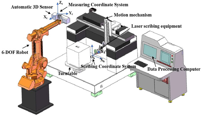
Figure 1 shows the developed 3D measurement and scribing system for complex workpieces. It consists of a 3D measurement subsystem and a laser scribing subsystem. The 3D measurement subsystem is composed of a 6-DOF robot, an automatic 3D measurement sensor. It is utilized to obtain the complete 3D shape of the complex workpiece, compare the 3D measurement result and the standard CAD model, and compute the allowance according to the need of machining processes and production schedules. The laser scribing subsystem consists of a high-precision motion mechanism, a turntable, and a laser scribing equipment. It could scribe the mechanical processing datum line on the complex workpiece to meet the process requirements, according to the result computed by the 3D measurement subsystem.
3 Algorithm principle
The 3D measurement and scribing system uses a structured-light 3D shape measurement sensor driven by an industrial robot with six-degree of freedom (6-DOF) is utilized to obtain the complete 3D shape of the complex workpiece automatically, and then the laser scribing equipment can automatically scribe the mechanical processing datum line to assist further processing, according to the result computed by comparing the 3D measurement result and the standard CAD model. In this process, the key technology is to complete the calibration and unification of multiple coordinate systems for 3D measurement sensor, 6-DOF robot, turntable, and high-precision motion mechanism, so a fast and accurate multiple coordinate systems calibration and unification method is proposed, a fixed calibration target and a mobile calibration target are designed.
In this section, the coordinate system establishment is first interpreted. Thereafter, the hand-eye calibration based on the fixed calibration target, the calibration of the measurement coordinate system and the scribing coordinate system based on the mobile calibration target and the rotation axis calibration of the turntable based on binocular vision are described in detail.
3.1 Coordinate system establishment
The scribing coordinate system OhXhYhZh is established based on the laser beam focus of the laser scribing equipment installed on the motion mechanism. The measurement coordinate system OcXcYcZc is established based on the automatic 3D measurement sensor. In order to realize the 3D scribing, the key is to calibrate the transformation between the measurement coordinate system and the scribing coordinate system, which is illustrated in Figure 1.
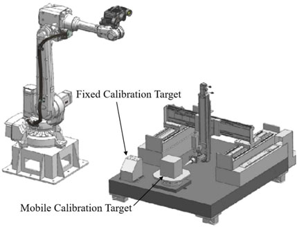
As shown in Figure 2, to unify the measurement coordinate system and the scribing coordinate system, a fixed calibration target and a mobile calibration target are designed. The fixed calibration target is fixedly installed on the corner of the marble platform of the high precision motion mechanism near the robot as the fixed benchmark of the whole system. The mobile calibration block is placed on the turntable and within the travel of the motion mechanism. By unifying the coordinates of the mobile calibration block and the fixed calibration block with the 3D measuring equipment, the problem of limited travel of the motion mechanism and inability to reach the fixed calibration target is solved by using the mobile calibration block as a transition. In addition, the placement can ensure that the laser scribing equipment can accurately align the circle markers on the mobile calibration target. After completing the calibration, the mobile calibration target can be removed.
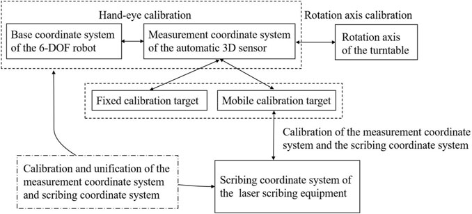
Figure 3 shows all coordinate systems can be unified through the fixed calibration target and the mobile calibration target. The base coordinate system of the 6-DOF robot and the measurement coordinate system of the automatic 3D measurement sensor are unified through the hand-eye calibration. The calibration of the rotation axis is based on the binocular vision system in the automatic 3D measurement sensor. The automatic 3D measurement sensor measures the circle markers on the mobile calibration target and the fixed calibration target to complete the coordinate unity of the two. There is a cross mark at the center of each circular mark. The laser beam focus aligns the circle markers on the mobile calibration target by the alignment b the focus and the cross mark, and the 3D measurement sensor measures the 3D coordinates of these circular markers, so that the transformation between the scribing coordinate system and the measurement coordinate system can be solved. In these ways, based on the fixed calibration target and the mobile calibration target, all coordinate systems are calibrated and unified. The key three steps are the hand-eye calibration based on the fixed calibration target, the calibration of the measurement coordinate system and scribing coordinate system based on the mobile calibration target, and the rotation axis calibration of the turntable based on the binocular vision system.
3.2 Hand-eye calibration based on the fixed calibration target
In the process of performing calibration of the measurement coordinate system with the scribing coordinate system, it is necessary to obtain the 3D coordinates of the marker points on the calibration block under the scribing coordinate system. However, the scribing machine cannot accurately measure the center coordinates of the marker point in the depth direction, so the automatic 3D measurement sensor is installed on the end of the 6-DOF robot to achieve accurate measurement of the coordinates in the depth direction. The rigid transformation between the 3D measurement coordinate system and the base coordinate system of the robot should be calibrated, so a fast and accurate hand-eye calibration method based on fixed calibration target is proposed.
A number of circle markers are pasted on the fixed calibration target. Use the automatic 3D measurement sensor to measure the circle markers to obtain the coordinates (Xci, Yci, Zci) of the circle markers in the 3D measurement coordinate system. The 3D measurement sensor scans and measures the circle markers on the calibration target from different positions, and the coordinates (Xb, Yb, Zb) in the base coordinate system of the 6-DOF robot can be calculated as follows:
where Rbi and tbi are the rotation matrix and translation vector between the flange and the base of the 6-DOF robot, which are calculated by the robot kinematics at the ith scanning. Rh and th are the rigid transformation between the 3D measurement coordinate system and the base coordinate system of the 6-DOF robot. When the circle markers on the fixed calibration target are scanned multiple times, the coordinate can be calculated as follows:
Then, the function can be formalized as follows:
Then, the function can be rewritten as:
Let
Then, the hand-eye calibration function is as follows:
When the robot carries the automatic 3D measurement sensor to complete the multi-directional scanning of the circle markers on the fixed calibration target, the hand-eye calibration matrix x can be calculated.
3.3 Calibration of measurement coordinate system and scribe coordinate system based on the mobile calibration target
After the hand-eye calibration is completed, the unification of the 3D measurement sensor coordinate system and the robot coordinate system is completed. To complete the scribing work, it is also necessary to realize the coordinate unification of the 3D measurement sensor coordinate system and the scribing coordinate system.
3.3.1 Mobile calibration target design
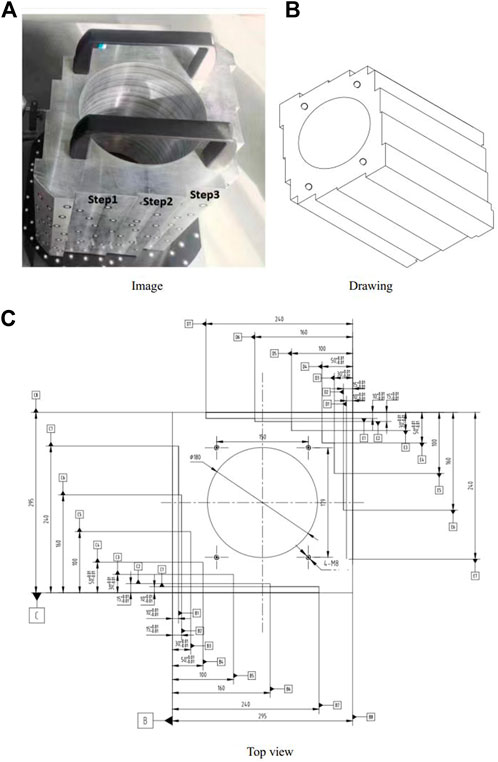
The motion mechanism is a high-precision four-axis platform (three linear axes and a turntable), and the laser scribing equipment does not have the function of center extraction and distance measurement. To obtain the coordinates of the marks points in the scribing coordinate system accurately, and to calibrate the transformation between the 3D measurement coordinate system and the scribing coordinate system, a special mobile calibration target is made, as shown in Figure 4. The mobile calibration target is precisely processed and measured, the bottom surface is perpendicular to the side surface through precision mechanical processing. Simultaneously, the side surface is precisely machined with 3 steps of different heights, and the height difference datum between the steps is precisely measured. Taking the first step as a reference, the height of each step is 0.00 m, 5.01 mm, 15.02 mm. Besides, a distance sensor is fixedly installed beside the laser scribing equipment for the measurement of the Y-axis coordinate.
3.3.2 Obtaining the center coordinates of the marker points in the scribing coordinate system
The mobile calibration target is placed on the turntable so that it is parallel to each axis of the motion mechanism. Some circle markers that can be recognized by the automatic 3D measurement sensor are randomly pasted on each step on the surface of the mobile calibration target, and between the fixed calibration target and the mobile calibration target. The 3D measurement sensor is driven by the 6-DOF robot to scan the circle markers on the fixed calibration block, ensuring that there are at least four to five common circle markers between two adjacent viewpoints. By the Multi-view point clouds registration and stitching, the coordinates Pg of the circle markers on the fixed calibration block and the coordinates Pc of the circle markers on the mobile calibration target in the measurement coordinate system can be obtained, thus the unification of the measurement coordinate system, the fixed calibration target coordinate system, and the mobile calibration target coordinate system is completed. On the premise that the mobile calibration target is not moved, the laser scribing equipment at the end of the motion mechanism is controlled to emit the laser beam focus, adjust the position to focus the laser on the plane of step 1, and make the laser beam focus coincide with the center cross of the first circle marker on step 1. In this case, this process is called point-to-point. At this time, the coordinate Ph1(xh1, yh1, zh1) of the center of the circle marker in the scribing coordinate system can be acquired. In the meantime, record the reading a1 of the distance sensor; move the movement mechanism to make the laser beam focus coincide with the center cross of the second circle marker on step 1, and record the reading a2 of the distance sensor. Then the coordinate of the center of the circle marker in the scribing coordinate system is Ph2(xh1, yh2 (zh1 + a1 − a2)), and so on, the coordinates Ph(xh, yh, zh) of all the circle markers in the scribing coordinate system are completed through the point-to-point. The rotation matrix R and translation vector t from the measurement coordinate system to the scribing coordinate system can be calculated as follows:
The formula is written as a homogeneous equation, as follows:
3.4 Calibration of the turntable
In the scribing process, the workpiece is required to be rotated multiple times to complete the laser scribing of each part of the workpiece. After the rotation, its reference line coordinates also change accordingly, hence, it is necessary to calibrate the parameters of the rotation axis of the turntable.
A high-precision rotation axis calibration method of the turntable based on binocular vision is proposed. The target image is obtained by using the principle of binocular stereo vision. Through high-precision space circle fitting algorithm and optimization, the rotation axis parameters of the turntable under the scribing coordinate system can be calibrated, and then obtained laser scribing data after the turntable is rotated.
3.4.1 Principles of binocular stereo vision
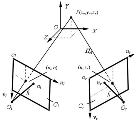
Figure 5 shows the binocular stereo vision model. OlXlYlZl and OrXrYrZr are the left camera coordinate system and the right camera coordinate system, respectively. Olulνl and Orurνr are the left image coordinate system in pixels and the right image coordinate system in pixels (xw, yw, zw) represents the 3D coordinates of a feature point P in the world coordinate system, which is the same feature point of the space object simultaneously observed by the left and right cameras. (ul, νl) and (ur, νr) respectively represent the undistorted homogeneous coordinates of P in the left image coordinate system in pixels and in the right image coordinate system in pixels.
From any point on the image surface of the left camera, as long as the corresponding matching point can be found on the image plane of the right camera (the two points are the same point in space on the left and right camera images), the 3D coordinate value of the point can be determined. Equations (8)–(10) provide the solution of the 3D coordinate value in the camera coordinate system.
Where sl and sr represent the non-zero scale factors, Kl and Kr are the intrinsic matrices of the left and right cameras, Rl and Tl are the rotation matrix and translation vector from the world coordinate system to the left camera coordinate system, respectively. Rr and Tr are the rotation matrix and translation vector from the world coordinate system to the right camera coordinate system, respectively. Ml and Mr are the perspective projection matrices of the left and right cameras. Xr and Xl are the 3D coordinates of the point P of the left and right cameras. Thus, the R and T from the left camera system to the right camera coordinate system could be calculated.
3.4.2 High-precision space circle fitting algorithm
The circle markers are elliptical after being imaged by the camera. After image edge extraction, the boundary of the image of thee circle markers is obtained, and then the center of the ellipse is optimized. The general equation of an ellipse on the plane is:
The above equation can be written in matrix form:
where
where li is the tangent line through the point ui on the ellipse.
Then adopt the weighted least squares method to solve the ellipse parameters, where wi is the weighting factor and n is the number of tangents.
Finally, the center coordinates of the ellipse can be calculated by the following equation:
3.4.3 Rotary axis calibration of turntable
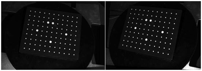
Rotation axis calibration of the turntable is the key to realize rotary scribing. First, the calibration plane is installed on the turntable at a certain angle and rotates with the turntable. Then, at each rotation position, the binocular vision system is used to collect the images of all marks on the calibration plane, as shown in Figure 6. Finally, the 3D coordinates of the marker points are calculated, and the linear equation of the rotation axis of the turntable is as follows:
where l, m and n are the normal vectors of the linear equation in space. The turntable calibration is completed.
4 Experiments and analysis
To verify the scribing accuracy and reliability of the RAS3DM method, an experimental platform of 3D measurement and scribing is constructed, which is shown in Figure 7. Therein, the automatic 3D measurement sensor consists of a digital raster projection profilometry device and two cameras. The image resolution of the camera is 1920 pixels × 1,200 pixels. The measurement accuracy of the automatic 3D measurement sensor is ±0.015 mm, and the measurement range is 430 mm × 280 mm. The payload of the 6-DOF robot is 6 kg, and the repositioning precision is ±0.02mm, the repositioning precision of the high-precision motion mechanism is ±0.005 mm, the repositioning precision of the turntable is ±0.001°, the laser scribing equipment power is 80 W, and the pulse frequency is 20 kHz ∼ 1,500 kHz. The experimental platform could simulate the 3D measurement, multi-coordinate system conversion, 3D repositioning and turntable conversion process in the actual 3D measurement and scribing of complex workpiece in the whole process.
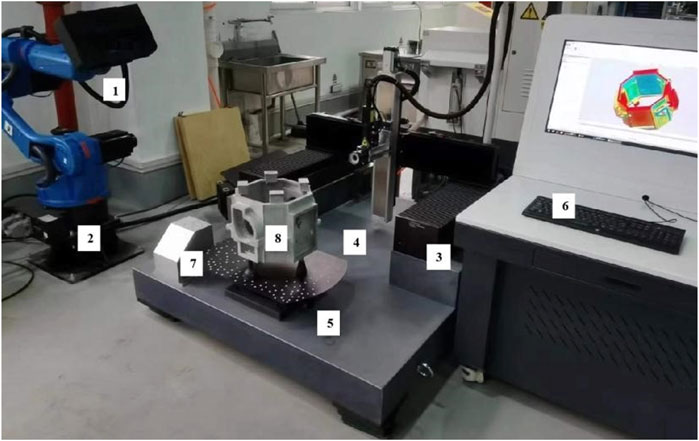
FIGURE 7. 3D measurement and scribing platform. It primarily comprises the following components: 1) automatic 3D measurement sensor, 2) 6-DOF robot, 3) high precision motion mechanism, 4) laser scribing equipment, 5) turntable, 6) Data Processing Computer, 7) fixed calibration target and 8) workpiece.
The workpiece used for the experiment is shown in Figure 8A. The workpiece has several irregular round holes and beveled surfaces, and it is difficult to accurately measure the allowance of each part and scribe the datum line by the traditional manual scribing method.
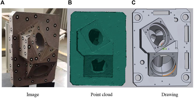
FIGURE 8. Workpiece used for the experiment. (A) Workpiece. (B) Point cloud of the workpiece. (C) 3D designed drawing of the workpiece.
4.1 3D measurement and scribing experiment
4.1.1 Obtain 3D point cloud
The workpiece is placed on the turntable of the 3D measurement and scribing platform. With the cooperation of the 6-DOF robot and the turntable, the 3D measurement sensor automatically obtain the complete 3D shape of the workpiece, as shown in Figure 8B. The whole scanning process takes 10 min.
4.1.2 Align according to the datum
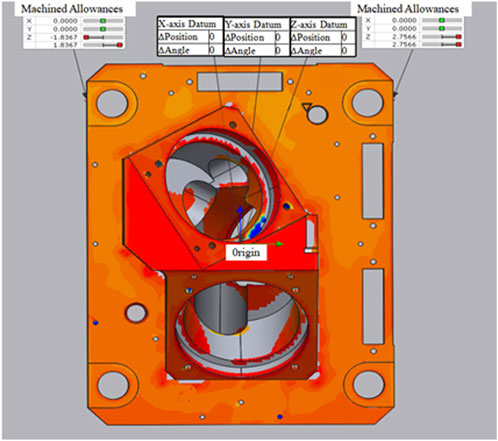
According to the alignment datum required by the process, as shown in Figures 8B,C, the 3D point cloud of the workpiece acquired in real time is aligned with the 3D designed drawing. Then, the system automatically calculates the allowance distribution of the workpiece and displays them as a color difference diagram, as shown in Figure 9. The warm color indicates the place where there is a large amount of mechanical processing allowance, and the cool color indicates the place where the mechanical processing allowance is lacking. The darker the color, the greater the value of excess or deficiency. It can be seen from Figure 8 that the surface of the workpiece is orange-red or red, which means that the machining allowance of each part is sufficient and there is no shortage.
4.1.3 Borrowing and adjusting the distribution of allowance
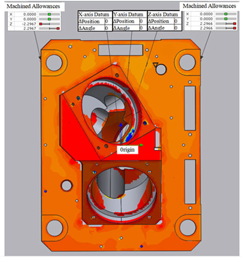
After calculating the allowance distribution, if the allowance distribution in the X, Y and Z directions does not meet the requirements of the machining processes, the allowance in that direction needs to be borrowed, that is, the datum in that direction needs to be translated, so as to redistribute the allowance of the workpiece, make it evenly distributed and meet the requirements of the machining processes. As shown in Figure 10, the allowance of the left and right sides of the workpiece is 1.84 and 2.76 mm respectively, with a difference of 0.92 mm. After the Z-direction datum is translated by 0.46 mm, the allowance on the left and right sides of the workpiece becomes 2.29 mm, and the allowance distribution is more uniform and reasonable.
Finally, according to the result of allowance adjustment, the coordinates of the mechanical processing datum line to be output are decomposed into several point coordinates, converted to the scribing coordinate system, and output to the laser scribing equipment. The whole calculation process takes about 3 min.
4.1.4 Laser scribing
According to the coordinates of the mechanical processing datum line in the scribing coordinate system, the laser scribing equipment scribes the datum line on the workpiece that meets the process requirements. As shown in Figure 11, the black line segment is the line segment scribed by the laser scribing equipment. The scribing time is 5 min.
4.2 Verification experiment of scribing accuracy
4.2.1 Principles of accuracy verification
Complex workpiece is automatically measured by 3D measurement sensor, and the datum coordinates of the initial scribing data are still in the measuring coordinate system after the datum alignment and allowance evaluation and borrowing. Therefore, it is necessary to convert the datum coordinates from the measuring coordinate system to the scribing coordinate system before scribing. Since the surfaces of the workpiece are uneven, traditional direct measurement method could not accurately measure the scribing accuracy. Therefore, in order to verify the scribing accuracy of the RAS3DM method, the cross circle markers pasted on the workpiece surface are the targets to be measured and improve the stability and accuracy of visual measuring.
The 3D measurement sensor, driven by the 6-DOF robot, automatically scans the surface of the workpiece and measures the circle markers, calculates the coordinates of the centre of the circle markers in the measurement coordinate system. Using the calibration of the measurement coordinate system and the scribing coordinate system, the coordinates of the circle markers are converted from the measurement coordinate system to the scribing coordinate system. At the same time, the workpiece is held still and the laser scribing subsystem is manually controlled to move with an accuracy of 0.005 mm, so that the laser beam focus coincides with the centre of the cross on the circle markers, and the current coordinates of the laser scribing subsystem are recorded as the true value of the circle markers centre coordinates. The coordinates of the circle markers measured by the proposed method is compared with the true value to analyze the scribing accuracy.
When it is necessary to rotate the turntable so that the surface of the workpiece to be scribed is facing the laser scribing equipment due to the travel limitations of the motion mechanism, the new measured coordinates of the surface circle markers are calculated using the rotation axis calibration of the turntable and the calibration of the measurement coordinate system and the scribing coordinate system. Finally, comparing the deviation between the real time measured value by the proposed RAS3DM method and the true value, the maximum deviation being the scribing accuracy.
4.2.2 Accuracy verification process
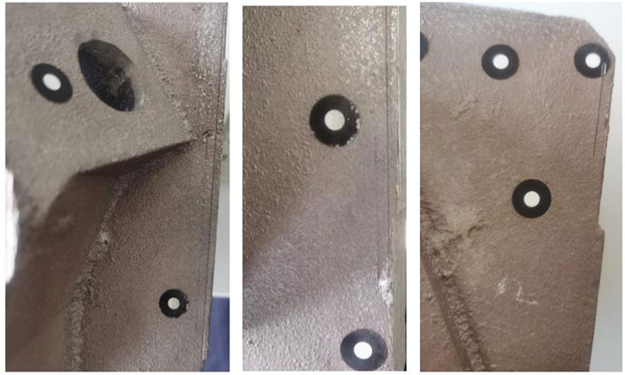
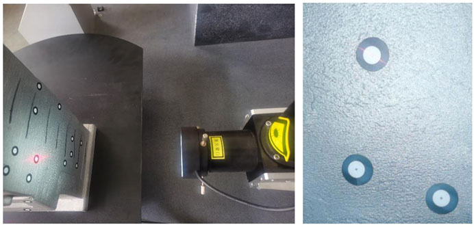
1. Define the four surfaces of the workpiece as 0° surface, 90° surface, 180° surface and 270° surface, which represent the angle at which the turntable needs to be rotated, and paste the circle marker with a cross in the centre of the circle on each surface, as shown in Figure 12, with multiple circle markers at random locations on each surface.
2. The 3D measurement sensor scans all circle markers on the surface of the workpiece and calculates the coordinates of the center of the circle markers in the measurement coordinate system.
3. Using the proposed measurement coordinate system and the scribing coordinate system calibration method, the center coordinates of the circle markers on the 0° surface are converted from the measurement coordinate system to the scribing coordinate system. The coordinate conversion results are the measurement values of the 0° surface.
4. Manually control the movement of the laser scribing subsystem so that the laser beam focus emitted by the laser coincides with the centre cross of the circle marker, as shown in Figure 12. The current coordinate values of the laser scribing subsystem are the true values of the 0° surface.
5. Rotate the turntable clockwise by 90°, and use the proposed measurement coordinate system and the scribing coordinate system calibration method and turntable rotation axis calibration method to convert the coordinates of the centre of the circle mark point on the 90° surface to the scribing coordinate system, the result of the conversion is the measured value of the 90° surface.
6. Repeat the above steps until all the mark points on the four surfaces of the workpiece have been measured, and finally calculate the system scribing accuracy.
4.2.3 Verification results
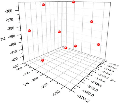
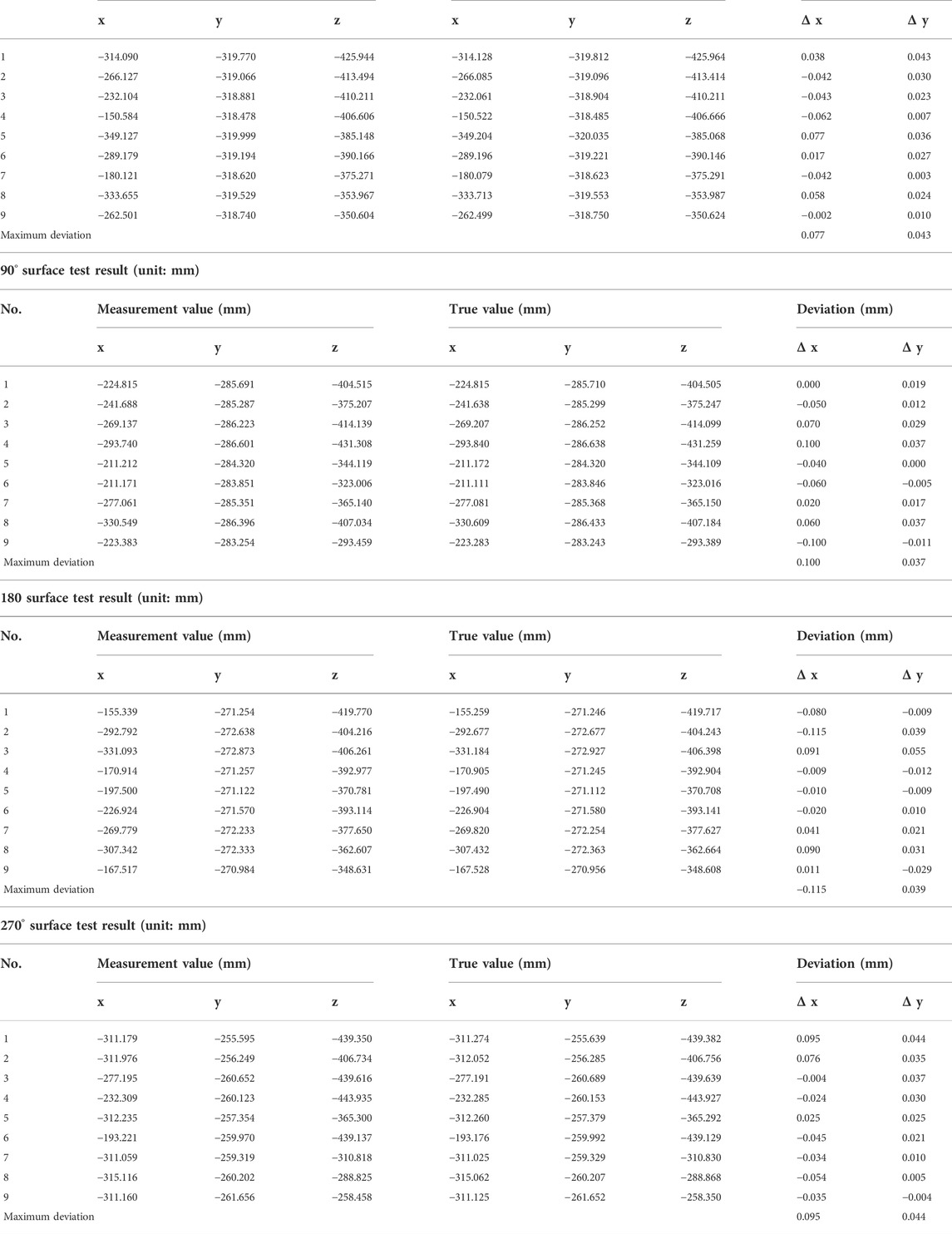
Figure 13 shows the distribution of the circle markers on the 0° surface. The circle markers are randomly and scatteredly distributed on the 0° surface, which fully simulates the uncertainty of the mechanical processing datum position and shows that the calculation results are representative. Table 1 shows the experimental data of all the mark points on the 0° surface, 90° surface, 180° surface and 270° surface. The experimental results prove that the maximum deviation of 0.077 mm on the 0° surface, 0.15 mm on the 90° surface, 0.137 mm on the 180° surface and 0.108 mm on the 270° surface, so the scribing accuracy of the proposed RAS3DM method is less than 0.15 mm.
4.3 Experiment summary
According to the research, it takes an experienced scriber between 1 and 3 h to manually scribe such complex workpieces, with an average of 90 min per workpiece and a scribing accuracy of 0.2–0.5 mm. The experiment proves that by using the proposed RAS3DM method for 3D measurement and scribing, the allowance distribution of complex workpiece is uniform and reasonable, the borrowing of the datum can be carried out according to the requirements of machining processes and production schedules, the laser scribing processing datum line is clear and can be directly docked for later finishing, the total allowance evaluation and scribing time is 18 min, which is 5 times faster than that of manual scribing, the scribing accuracy is 0.15 mm, which is 0.2 mm higher than the average of manual scribing accuracy. Therefore, the proposed RAS3DM method can effectively solve various problems of current manual scribing, and the efficiency and accuracy are greatly improved.
5 Conclusion
This paper proposes a RAS3DM method to facilitate automatic 3D measurement and scribing of the complex workpieces. By analyzing the difficulties of manual 3D measurement and scribing, such as low efficiency, easy to misjudge, unable to deal with irregular surfaces, and large blind areas, a fixed calibration target and a mobile calibration target are designed. And a hand-eye calibration method based on the fixed calibration target is introduced, a calibration method of the measurement coordinate system and the scribing coordinate system based on the mobile calibration target is designed to calibrate the rigid transformation between different coordinate systems, and the corresponding the rotation axis calibration of the turntable based on binocular vision is derived. Thus, based on the robot-driven automatic 3D measurement and scribing, the complex workpiece allowance is evaluated and the datum lines are scribed, which improved the 3D measurement and scribing precision and efficiency.
The proposed 3D measurement and scribing method is verified through real data experiments. Experimental results indicated that the 3D measurement and scribing process can complete automatically if the proposed method is adopted. To evaluate the precision, real-time performance, and efficiency of the proposed RAS3DM method, it is compared with the manual scribing method. Using the proposed method, the allowance distribution of complex workpiece is uniform and reasonable, the borrowing of the datum can be carried out according to the process requirements, the laser scribing processing datum line is clear and can be directly docked for later finishing, the total measuring and scribing time is 18 min, which is 5 times longer than that of manual scribing, the scribing accuracy is 0.15 mm, which is 0.2 mm higher than the average of manual scribing accuracy. Therefore, the proposed RAS3DM method can effectively solve various problems of current manual scribing, and the efficiency and accuracy are greatly improved.
Furthermore, to improve the 3D measurement and scribing operation convenience of complex workpieces on-site, the structural miniaturisation and low cost design of the 3D measurement sensor and the motion mechanism are considered. A further study will be conducted by applying this method to a real 3D measurement and scribing system. In an actual 3D measurement and scribing process, the performance of the proposed RAS3DM method can be influenced by the manufacturing accuracy of the complex workpiece, measurement precision of the circle markers, and positioning precision of the motion mechanism. In the future, a method that can coordinate these precision will also be researched to improve 3D measurement and scribing quality.
Data availability statement
The original contributions presented in the study are included in the article/supplementary material, further inquiries can be directed to the corresponding author.
Author contributions
HL, KZ, and Zhongwei Li contributed to conception and design of the study. HL, KZ and Zhongwei Li organized the database. HL, PL and RL performed the statistical analysis. HL and Zhongwei Li contributed to project administration and funding acquisition. RL wrote the first draft of the manuscript. HL,KZ, PL and Zhongwei Li wrote sections of the manuscript. All authors contributed to manuscript revision, read, and approved the submitted version.
Funding
This research is supported by the National Key Research and Development Program of China (No. 2018YFB1305700).
Conflict of interest
The authors declare that the research was conducted in the absence of any commercial or financial relationships that could be construed as a potential conflict of interest.
Publisher’s note
All claims expressed in this article are solely those of the authors and do not necessarily represent those of their affiliated organizations, or those of the publisher, the editors and the reviewers. Any product that may be evaluated in this article, or claim that may be made by its manufacturer, is not guaranteed or endorsed by the publisher.
References
1. Margerit P, Gobin T, Lebée A, Caron JF. The robotized laser Doppler vibrometer: On the use of an industrial robot arm to perform 3d full-field velocity measurements. Opt Lasers Eng (2021) 137:106363. doi:10.1016/j.optlaseng.2020.106363
2. Wang J, Tao B, Gong Z, Yu S, Yin Z. A mobile robotic measurement system for large-scale complex components based on optical scanning and visual tracking. Robotics and Computer-Integrated Manufacturing (2021) 67:102010. doi:10.1016/j.rcim.2020.102010
3. Suresh V, Liu W, Zheng M, Li B. High-resolution structured light 3d vision for fine-scale characterization to assist robotic assembly. Dimensional Opt Metrology Inspection Pract Appl X (2021) 11732:1173203. (SPIE). doi:10.1117/12.2589755
4. Hong Y, Li C, Yun C. Robot grinding system for 3d complex surface processing. China Mech Eng (2006) S2:150–3.
5. Wang H, Yan G, Ding G. Automatic scribing and cutting system of machine and human profile based on fatigue compensation algorithm. J Shanghai Jiaotong Univ (2002) 36:991–4. doi:10.3321/j.issn:1006-2467.2002.07.023
6. Wan G, Wang G, Xing K, Yi T, Fan Y. 6dof object positioning and grasping approach for industrial robots based on boundary point cloud features. Math Probl Eng (2020) 2020:1–12. doi:10.1155/2020/9279345
7. Guo X, Shi Z, Yu B, Zhao B, Li K, Sun Y. 3d measurement of gears based on a line structured light sensor. Precision Eng (2020) 61:160–9. doi:10.1016/j.precisioneng.2019.10.013
8. Yu H, Huang Y, Zheng D, Bai L, Han J. Three-dimensional shape measurement technique for large-scale objects based on line structured light combined with industrial robot. Optik (2020) 202:163656. doi:10.1016/j.ijleo.2019.163656
9. Liu J, Jia X, Wang N, Li T. Research on tool geometry parameter measurement based on surface structured light projection. Chin J Scientific Instrument (2017) 38:1276–84. doi:10.3390/s20174843
10. Sha X, Ma J. Research and application of digital inspection method for large parts size. Foundry Equipment Tech (2020) 3:26–42. doi:10.16666/j.cnki.issn1004-6178.2020.03.009
11. Xu Z, Zheng C. Application of 3d scanning technology in new product development and process quality control. China Foundry Equipment Tech (2018) 53:34–8. doi:10.3969/j.issn.1006-9658.2018.06.009
12. Ma Q, Wang D. Analysis on the problems existing in the mechanical line marking machine and the improvement measures. China South Agric Machinery (2017) 48:8. doi:10.3969/j.issn.1672-3872.2017.02.004
Keywords: complex workpiece, mechanical processing allowance, datum line, 3D scribing, 3D measurement sensor
Citation: Luo H, Zhang K, Li R, Liang P and Li Z (2022) A robot-driven automatic scribing method via three-dimensional measurement sensor. Front. Phys. 10:979447. doi: 10.3389/fphy.2022.979447
Received: 27 June 2022; Accepted: 14 September 2022;
Published: 04 October 2022.
Edited by:
Santosh Kumar, Liaocheng University, ChinaReviewed by:
Dharmendra Kumar, Madan Mohan Malaviya University of Technology, IndiaAnkur Saharia, Manipal University Jaipur, India
Copyright © 2022 Luo, Zhang, Li, Liang and Li. This is an open-access article distributed under the terms of the Creative Commons Attribution License (CC BY). The use, distribution or reproduction in other forums is permitted, provided the original author(s) and the copyright owner(s) are credited and that the original publication in this journal is cited, in accordance with accepted academic practice. No use, distribution or reproduction is permitted which does not comply with these terms.
*Correspondence: Hua Luo, bG91aGVhdGhlckAxNjMuY29t
 Hua Luo
 Ke Zhang
 Ruifeng Li
 Peidong Liang3