
95% of researchers rate our articles as excellent or good
Learn more about the work of our research integrity team to safeguard the quality of each article we publish.
Find out more
ORIGINAL RESEARCH article
Front. Phys. , 25 August 2022
Sec. Atomic and Molecular Physics
Volume 10 - 2022 | https://doi.org/10.3389/fphy.2022.971099
This article is part of the Research Topic Quantum Precision Measurement and Cold Atom Physics View all 17 articles
 Xiumei Wang1,2
 Jin He1*Yifei Wang2Yunjia Wang2Wenming Wang2Weili Wang2Shiguang Li2Xi Zhu2Guodong Liu2Shuo Liu2Ye Wang2Liang Wang2Yaxuan Liu2Tongmin Yang2Chunyan Cao2Yiqun Wei3*Yutao Yue3Guoqing Hu1Zhenfeng Liu4Yimin Pan4Lianshan Gao2*
We demonstrate the construction of the optical system in the atomic clock-beyond atomic fountain based on 87Rb atom. The optical system includes a high-stability laser system and an optical lattice. The high-stability laser system with the new scheme of frequency locking and shift is introduced in detail, which is an important laser source for laser cooling. The optimized frequency and intensity stability are achieved to 4 × 10–14
Laser cooling can produce the cold atoms with low temperature and high density, which has been widely used in different fields, such as atomic clocks [1–5], atomic interferometer [6–8], atomic optics [9], Bose-Einstein condensate (BEC) [10, 11], quantum computing [12], quantum communication [13], etc. The atomic clocks can provide the unprecedented precision in the determination of time and the SI second is experimentally determined by measuring the 133Cs hyperfine transition with atomic fountain clocks [14]. However, due to the gravity, the usual coherent interrogation time of the atomic fountain clock reaches around one second. The more longer coherent interrogation time in the atomic fountain clock on Earth seems impractical. However, the cold atoms trapped in the optical traps can be stored with a long lifetime even up to hundreds of seconds with negligible optical scattering and minimal laser-noise-induced heating [15, 16]. Using this method, the optical trapping without affecting the internal energy-level of the atoms is desirable, which is attractive particularly in the atomic fountain clock. Some authors have proposed a novel microwave atomic clock, combining the atomic fountain clock and optical lattice configurations [17, 18]. Compared with the conventional atomic fountain clock, the new microwave atomic clock with higher frequency stability and accuracy can be achieved. This new microwave atomic clock is called beyond atomic fountain clock, which is abbreviated to the “beyond fountain” [17]. In the beyond fountain, not only the coherent interrogation time is increased to improve the frequency stability of 10–15 at one second, but also the frequency accuracy of 10–15 to 10–17 is feasible, due to the dramatic elimination or suppress of the cavity related shifts, the collision shift and the Doppler effect [18]. They have proven that we can attempt to overcome the limitation of coherent interrogation time, when the cold atoms are trapped in the optical lattice. This microwave atomic clock provides an easy way to improve the atomic fountain clock performance by adding a trapping laser beam in the conventional atomic fountain clock without any further complicated modifications. It is still feasible to achieve the microwave atomic clock for 87Rb or 133Cs cold atoms with a high accuracy even though no magic wavelength exists [18], in contrast to the optical lattice clocks employing a dipole trap at a magic wavelength to suppress the differential light shift. Besides, based on the proposal of the beyond fountain, several approaches have been predicted to further suppress the differential light shift, such as magic wavelengths on microwave transitions for Al and Ga [19], the laser traps of particular polarization combined with a specific magnetic field [20, 21] and the cancellation at the expense of a small magnetic-field sensitivity [22].
The beyond fountain has attracted much attention and it is of great practical significance to develop to broaden the field of microwave atomic clock. However, in the beyond fountain, the preparation of cold atoms is primary to provide the atomic medium and the optical lattice is utilized to trap the cold atoms for long coherent interrogation time. On the basis of conventional atomic fountain clock, the beyond fountain can prepare the cold atoms in the magneto-optical trap (MOT) zone directly and the optical lattice can be specially designed with the upward movement of cold atoms. For the cold atoms, the quality of laser frequency locking and the fluctuation of cold atoms number caused by the laser intensity are still problems, because they seriously determine the hyperfine transition of laser cooling and the stability of cold atom number. For the optical lattice, it should be investigated to optically load and trap atoms along the gravity, which coincides with the atomic trajectory from the conventional atomic fountain clock. It is obtained that the construction of the optical system including a high-stability laser system and an optical lattice is very necessary in the beyond fountain, which will meet the laser cooling and optical trapping requirements of cold atoms.
In this paper, the construction of the optical system in the beyond fountain based on 87Rb atom is proposed. The high-stability laser system with the new scheme of frequency locking and shift is introduced in detail, which is an important laser source for laser cooling. In the high-stability laser system, we have built the diode laser with narrow linewidth and measured the optimized frequency and intensity stability. Together with the MOT, the laser system is expected to capture the cold atoms with μK temperature by Doppler and sub-Doppler cooling mechanism. These cold atoms are prepared to be loaded into the optical lattice. On the basis of the conventional atomic fountain clock, the optical lattice is specially investigated along the direction of gravity, which is located above the Ramsey microwave cavity. This engineered scheme can realize the optical lattice and the performance for trapping can be observed directly. It is predicted that the cold atoms can be loaded into the optical lattice by an appropriate time sequence successfully. Thus, the investigation on the construction of the optical system will effectively promote the development of the beyond fountain.
As shown in Figure 1, we consider an experimental scheme of 1D optical lattice in the physical package of the beyond fountain, which is the combination of atomic fountain clock and optical lattice configurations. In contrast to the complexity of 2D and 3D optical lattices [23], the 1D optical lattice is formed by two counter-propagating laser beams [24–26], which is uncomplicated and can be integrated with the atomic fountain clock along the direction of gravity by the standing wave. Compared with the optical dipole trap (ODT) formed by a traveling wave, the potential well depth at the laser beam waist of the 1D optical lattice is four times larger than the ODT, with the identical laser intensity. The 1D optical lattice can cause the more attractive force for the cold atoms than the ODT, which will contribute the more tightly confining cold atoms. So the 1D optical lattice is chosen over the ODT. To facilitate the integration, the optical lattice laser is injected above the vacuum tube of the atomic fountain clock by an optical cage structure and reflected by the mirror at the bottom of MOT zone. Using the 1D standing wave, the optical lattice can be produced above the Ramsey microwave cavity. The launching cold atoms from the MOT zone can be loaded into the 1D optical lattice and trapped for a long time before releasing. The 1D optical lattice is designed to minimize any structure distortion, which hardly affects the vacuum environment and microwave oscillation. Two optical windows are established at the top of the vacuum tube and the bottom of the MOT zone for the injection and reflection of laser. Several windows are established at the sides of the vacuum tube for the injection of probe laser and the observation of fluorescence from cold atoms in the optical lattice. These optical windows are vacuum sealed and nonmagnetic. An electronic multiple charge coupled device (EMCCD) needs to be installed outside of the vacuum tube to observe the fluorescence from the cold atoms.
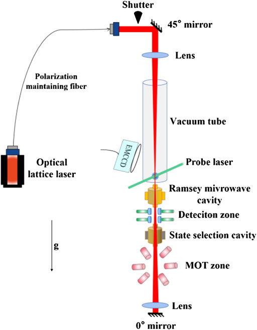
FIGURE 1. The experimental scheme of 1D optical lattice in the physical package of the beyond fountain.
In order to load the cold atoms into the optical lattice as much as possible, the potential well depth is predicted to tens of microkelvin temperature and the cold atoms should be cooled to several microkelvin temperature in MOT zone. In addition, we assume that the velocity of cold atoms is almost zero, when the cold atoms reach to the position of optical lattice. That means the cold atoms are loaded under static condition and then trapped in the ultra-high vacuum environment. It is worth noting that the cold atoms launching from the MOT zone should have a good stability to ensure the uniformity of trapped cold atoms in every duty cycle. The coherent interrogation time are mainly determined by the optical lattice depth, the beam waist and the vacuum environment.
In the MOT zone, the laser system including the cooling and repumping light [3, 27, 28] is used in the cold atom experiments. These lights interact with the hyperfine energy level of atoms, so the linewidth of them should be reduced preferably to hundreds of kHz or tens of kHz. The stability of cold atom number are determined by the stability of cooling light, so the cooling light requires the sufficient stability of laser wavelength, single mode and intensity. The factors affecting the laser stability can be divided into the external and internal factors. The external factors include mechanical vibration, temperature, pressure, magnetic field, etc. The internal factors include spontaneous emission, power supply circuit, aging, etc. Therefore, it is very important to reduce the linewidth and improve the laser stability by the locking technology. There are many frequency locking schemes, such as dichroic atomic vapour laser lock (DAVLL) [29], polarization spectroscopy [30], frequency modulation spectroscopy [31], Pound-Drever-Hall (PDH) [32], saturation absorption spectroscopy (SAS) [33] and modulation transfer spectroscopy (MTS) [34]. Among them, the usual SAS modulates the laser frequency by current and the laser frequency is locked by the negative feedback loop, in which the additional laser noise will be introduced to the output laser. Compared with the widely used SAS, the MTS with the external modulation can avoid the modulation disturbance to the output laser. Here, we develop the MTS technology to achieve the frequency stabilization. This technology does not modulate the frequency of the output laser, so it will not bring the additional noise. Besides, the slope of the error signal is large and the background noise is small, which is beneficial for the frequency locking. For the stabilization of laser intensity, in order to achieve the desired performance, it is necessary to select an appropriate device as the feedback actuator and an acousto-optic modulator (AOM) will be suitable.
To achieve the narrow linewidth and improve the stability of laser frequency, the laser system for laser cooling is optimized. As shown in Figure 2, the new scheme of laser frequency locking and shift is proposed. In the scheme, an external cavity diode laser (ECDL) and a distribution feedback Bragg (DFB) laser allow us to minimize the number of laser source and simplify the laser frequency shift processes. The frequency of the ECDL is locked to the 87Rb D2 line F = 2→F’ = 3 by MTS and then shifted to form the frequency of the cooling and probe lights simultaneously. One basic light resonant with D2 line F = 2→F’ = 2 is formed by the negative frequency shift from the locked frequency of the ECDL. The cooling light (red-detuning of D2 line F = 2→F’ = 3) is formed by the positive frequency shift from the basic light. The probe light (near resonance of D2 line F = 2→F’ = 3) is also formed by the positive frequency shift from the basic light. The DFB laser offers the repumping light, whose frequency is locked to the D2 line F = 1→F’ = 1&2 by SAS. The repumping light is formed by the positive frequency shift from the DFB laser, because its frequency is resonant with D2 line F = 1→F’ = 2. The scheme of the optical path with four laser frequency shift processes will be realized by the acoustic-optical modulators (AOMs). In the above process, the expected characteristics of lights in the laser system is shown in Table 1. It is worth noting that the cooling light has different detuning and power in the different laser cooling stage.
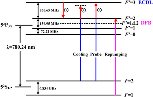
FIGURE 2. The scheme of laser frequency locking and shift for 87Rb.
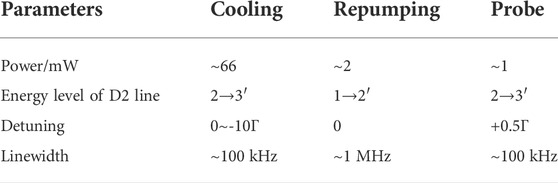
TABLE 1. The requirement of laser beams in the laser system with87Rb.
In the laser system, an interference-filter-type ECDL (IF-ECDL) offers an ultra-narrow interference filter to replace the alignment-sensitive diffraction grating in the conventional Litman-Metcalf-type and Littrow-type [35, 36]. It is easier to achieve the narrow linewidth and the sufficient stability of laser frequency, due to the insensitivity to the pressure, mechanical, thermal strain, etc. As shown in Figure 3, instead of the diffraction grating, a narrow bandwidth interference filter and a cat’s eye mirror are placed for wavelength selection and optical feedback, respectively. The emitted light from the laser diode is collimated using an aspheric lens and the collimated beam passes through an interference filter. The collimated beam is then focused on the surface of the cat’s eye mirror by an aspheric lens. The piezoactuator having external threads on one side is attached to the cat’s eye mirror with a threaded cap. Finally, the output laser is collimated by an additional aspheric lens. All the optical components are integrated and the length of the external cavity is about 73 mm. The output single mode and the laser wavelength are fine-tuned by the voltage applied to the piezoactuator. Not only the output laser with the wavelength 780 nm, the frequency no-hopping range 5–20 GHz and the linear polarization has been obtained, but also the laser linewidth well below 100 kHz has been achieved successfully.
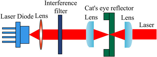
FIGURE 3. The scheme of IF-ECDL.
To stabilize the laser frequency of the IF-ECDL, the MTS is applied. Figure 4 shows the experimental set-up for the frequency stabilization by MTS. This modulation transfer is described as an example of four-wave mixing, which only takes place when the sub-Doppler resonance condition is satisfied. This leads to the flat, zero background signal and the position of the zero-crossing always falls on the centre of the sub-Doppler resonance. The IF-ECDL is used to provide the laser at 780 nm with an optical isolator to prevent the laser being reflected back into the IF-ECDL. Two counter-propagating laser beams can be referred as the pumping and probe lights as in SAS [37], and two polarizing beam splitters (PBSs) are utilized to split and then overlap the two lights. A free-space electro-optic modulator (EOM) is driven by an oscillator at the modulation frequency ωm and applied as the phase modulator to provide the sideband-offset for pumping light. The transmission of the EOM is greater than 98% and its aperture is 3 × 3 mm for easy alignment. The transmitted phase-modulated pumping light can be represented in terms of the carrier and sidebands frequency separated by the modulation frequency ωm. The phase modulated pumping light and the counter-propagating, unmodulated probe light are aligned through an 87Rb vapour cell. If the interaction of the pumping and probe lights with the atomic vapour are sufficiently nonlinear, the modulation will appear on the unmodulated probe light. After passing through the vapour cell, the probe light is incident on a photo-detector (PD). The sidebands frequency of the probe light generated in the vapour beats with the carried frequency of the probe light to produce an alternating signal at the modulation frequency ωm. This alternating signal is mixed with the RF signal to generate the MTS signal, and the MTS signal can be used to feedback the IF-ECDL. The size of optical components in Figure 4 has been miniaturized and the optical simplification of the experimental setup is convenient for the integration with the IF-ECDL to be locked.

FIGURE 4. The experimental set-up for the frequency stabilization by MTS.
To stabilize the laser power of the IF-ECDL, an AOM can be used with an electrical drive signal [38]. It is based on the acousto-optic effect, i.e., the modification of the refractive index of the crystal material by the oscillating mechanical strain of a sound wave. A piezoelectric transducer attached to the crystal obtains a strong oscillating electrical signal from a RF driver and is used to excite a sound wave. The sound wave generates a traveling strain wave in the crystal material. The photo-elastic effect leads to a traveling refractive index grating, at which the light can experience the Bragg diffraction. The angle of Bragg diffraction
where
where
The optical lattice is the periodic dipole trap formed by the opposite laser beams, which is located above the Ramsey microwave cavity. The space-time atomic trajectory for loading is shown in Figure 5. The 87Rb atoms are laser-cooled to about 2 μK, prepared in the D2 line F = 2 state, and then launched into the free fall. After the launch, the atomic trajectory includes the upper half part of MOT zone, selection microwave cavity, detection zone and Ramsey microwave cavity. The launched cold atoms reach the apex after 400 ms of free fall time (corresponding to height from the center of MOT zone to the optical lattice Δh≈800 mm). At the apex, the counter-propagating laser beams are turned on and the cold atoms are loaded into the optical lattice. Then the cold atoms will be stored for a time τL. If the cold atoms with kinetic energy lower than the potential well depth, they will be trapped for a long time. Upon turning off the counter-propagating laser beams, the optical lattice will disappear and the cold atoms will be released into the free fall, due to the gravity.
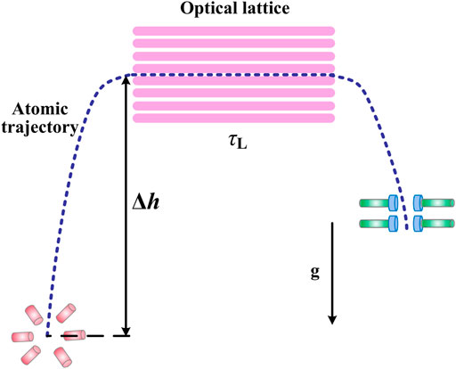
FIGURE 5. Space-time atomic trajectory for loading.
Let us consider the two counter-propagating laser beams of linear polarization and of the same wavelength. The potential well depth experienced by the cold atoms
where P is the laser power,
where
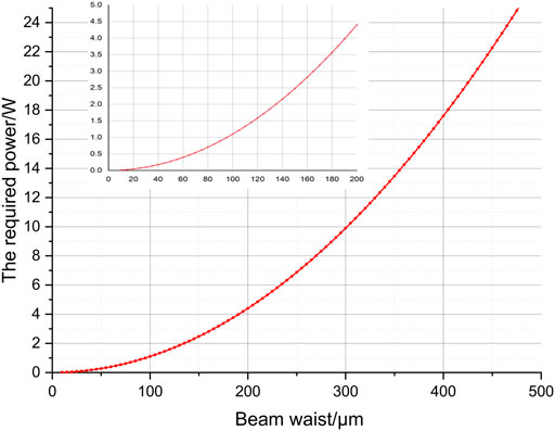
FIGURE 6. The required power versus the beam waist in case of potential well depth
The radius of cold atom cloud in the MOT zone
where
and the number of trapped cold atom will take the form
As shown in Figure 7, the larger beam waist leads to the more number of trapped cold atom. However, a large number of cold atom trapped will require much more laser power. Therefore, it is necessary to take the appropriate beam waist and laser power for the optical lattice in the experiment. Under our experimental conditions, it would be proper to take the laser power about
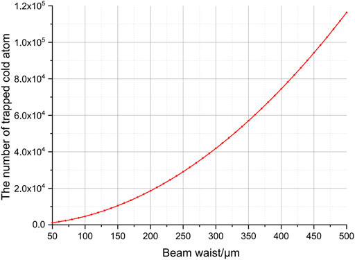
FIGURE 7. The number of trapped cold atom versus the beam waist of the optical lattice.
Figure 8 shows the schematic diagram of the optical path for laser cooling. Details on the energy level and the specifications of the IF-ECDL have been described in Section 2.2. For the experimental set-up, an IF-ECDL and a DFB laser at the same wavelength 780 nm are applied, whose frequencies are locked to D2 line F = 2→F’ = 3 by MTS and D2 line F = 1→F’ = 1&2 by SAS, respectively. The power IF-ECDL is about 100 mW, which is necessary to be amplified to provide the cooling and probe lights. Considering the difficulty of optical tuning, the power is amplified sufficiently to 3 W and a single-mode polarization-maintaining fiber is applied to introduce the laser beam to the optical bench. After the fiber, the laser beam is collimated and beam diameter is about 1 mm. This laser beam is then shifted to F = 2→F’ = 2 by an AOM, which is divided into three lights: one cooling light in the upward direction at the bottom half of MOT zone, one cooling light in the downward direction at the upper half of MOT zone, and one probe light for fluorescence detection. These lights require the different RF frequency and power driving on AOMs for the control of their detuning. In addition, these AOMs allow the laser frequency to be tuned without optical path changing. The repumping light is achieved by the DFB laser and an AOM, which is the usual approach in the atomic fountain clock. Some fiber beam splitters will be applied to introduce these lights to the MOT or detection zone to interact with atoms in the vacuum. All lasers can be continuously monitored by the PD and two mechanical shutters are installed for the time sequence.
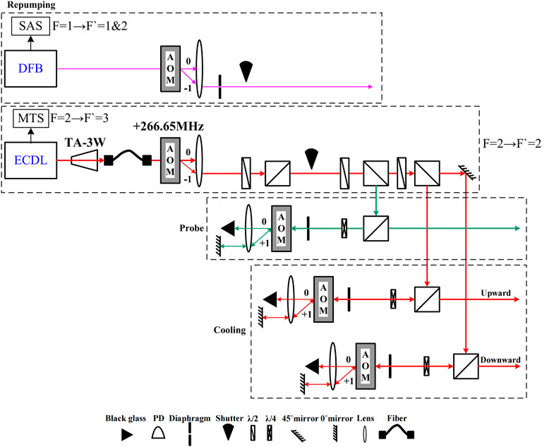
FIGURE 8. The schematic diagram of the optical path for laser cooling.
The laser power of IF-ECDL for laser cooling is strongly dependent on the diffraction of AOM, so the AOM is selected as a feedback device for the control of laser power. Figure 9 shows the scheme of stabilizing the laser power with an AOM. The first-order diffraction beam is picked up by a 0° mirror and turned back for the second pass-through of the AOM. Some of them are reflected by a PBS and monitored by the PD in the in-loop. The in-loop signal of the PD is compared to a reference voltage issued from a voltage reference with low noise and low drift. After the comparison, the error signal shows the difference between the PD signal and the voltage reference and it will be applied to the diffraction efficiency of the AOM. Due to this procedure, the fluctuation of laser power can be decreased.
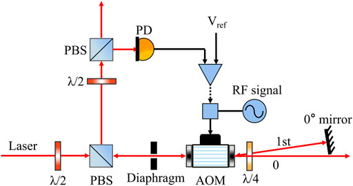
FIGURE 9. The scheme of stabilizing the laser power with an AOM.
The optical lattice employs the large red-detuning from resonance to achieve the long trapping time, in which the cold atoms are trapped at antinodes. In our experiment, an amplified tunable diode laser with high power up to 3 W is applied, whose wavelength is 852 nm. After the fiber coupling, the laser power is estimated to be 1 W. We can build the optical lattice with this power value. From Figure 6 and Figure 7, it is obtained that the beam waist is about 100 μm and the number of trapped cold atom is about 4,650. Although the number of trapped cold atom is not large enough for the clock signal, it is still beneficial for loading and observing the cold atoms in the optical lattice. If the diode laser with higher power is offered, the more cold atoms will be trapped. Figure 10 shows the optical path for trapping in the optical lattice built by the available laser. According to Figure 1, it is difficult to focus at the apex of the free fall with the usual lens, because of the long distance between the center of MOT zone and the Ramsey microwave cavity. Therefore, the lens is specially customized with the diameter of D = 25.4 mm and focal length f = 900 mm, which is designed to meet the beam diameter for two counter-propagating laser beams. For the lens, if the radius of curvature is much greater than the focal length, the beam waist
where
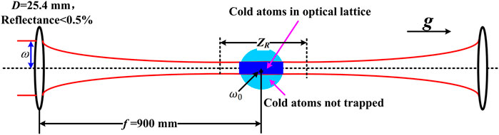
FIGURE 10. The schematic diagram of optical path for optical lattice.
Once the optical lattice is home-built successfully, the centers of the optical lattice and cold atom cloud should coincide as much as possible. It is necessary to be carefully adjusted in the experiment. The atomic transition in optical lattice is excited by the probe light, and we observe the fluorescence image of cold atoms from the EMCCD to evaluate the coincidence. When the fluorescence image of the trapped cold atom cloud reaches to the brightest, and the width of the cold atom cloud is close to the beam waist, it can be considered that the centers of the optical lattice and cold atom cloud accurately coincide [39]. For the coarse adjustment, the center of the optical lattice can be moved by the two lenses along the direction of gravity. When the coarse adjustment is completed, more fine adjustment and calibration on the angle of the incident light are required. Recently, we have built a miniaturized vacuum system with about 2 × 10⁻⁷Pa for 133Cs shown in Figure 11. Although it is not for 87Rb, it can also be used for laser cooling and applied as an apparatus to optically trap cold atoms by the optical lattice.
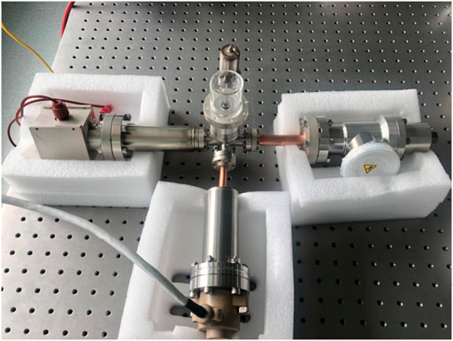
FIGURE 11. The miniaturized vacuum system.
As shown in Figure 12, the time sequence for the preparation and loading of cold atoms is proposed from the atomic fountain clock, which is used for the experiments of cold atoms. The atoms are laser-cooled to about 10 μK at the MOT and Molasses cooling stage, and launched into the free fall. At the beginning of the free fall, the post-cooling further reduces the temperature of atoms to about 2 μK. Then at the free fall, the cold atoms will travel through the upper half part of MOT zone, selection microwave cavity, detection zone and Ramsey microwave cavity. At the apex of the free fall, the cold atoms just pass the Ramsey microwave cavity and are loaded into the optical lattice. The cold atoms will be trapped into the optical potential well for a long time. This trapping time is the desired parameter to evaluate the performance the optical lattice. Then the cold atoms trapped in the optical lattice are detected by the pulsed probe light (near resonance of D2 line F = 2→F’ = 3). At the same time, in order to observe the fluorescence image from optical lattice, an EMCCD is placed outside of the vacuum tube. The experimental detuning and power parameters of probe light can be optimized by observing the fluorescence image. In this time sequence, the mechanical shutters are turned on and off for the time control.
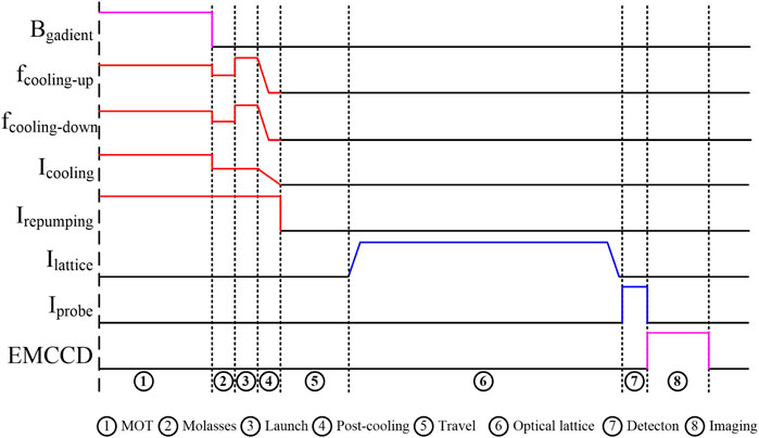
FIGURE 12. Time sequence for the preparation and loading of cold atoms for optical lattice.
The laser frequency of the IF-ECDL depends on the temperature and diode current. The temperature has an impact on the length of the external cavity, which is actively monitored by a negative temperature coefficient (NTC) thermistor and controlled by a thermo electric cooler (TEC). This active temperature control will be combined with the external cavity length feedback to stabilize the laser frequency. As shown in Figure 13A, the output laser power of the IF-ECDL versus the diode current has been measured. Once the current is higher than the specific threshold 25 mA, the output laser power is almost linear to the diode current and can be over 100 mW. During operation, the diode current should be set above the threshold and well below the nominal maximum. Besides, we must effectively narrow the laser linewidth to avoid mode hopping and drift, because the laser cooling require the laser with low noise and high frequency stability. As shown in Figure 13B, the frequency beat-note signal of our laser with another IF-ECDL shows that the laser frequency noise is suppressed effectively, and the linewidth of about 75 kHz is achieved. A master oscillator power amplifier (MOPA) is applied to amplify the output laser of the IF-ECDL, which is used as the seed laser. The power of the seed laser between 10 and 30 mW can be amplified up to nearly diffraction limited power values in the Watt-range. Here, the temperature of the MOPA is lower than the room temperature and the difference between them should be as small as possible, which is beneficial to avoid the condensation on the surface of the MOPA.
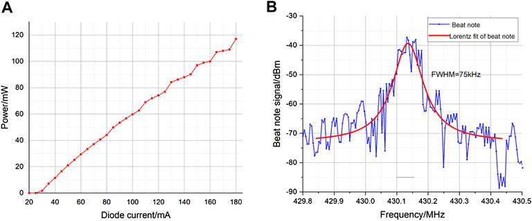
FIGURE 13. The characteristic of the IF-ECDL (A) the output laser power versus the diode current (B) the frequency beat-note signal with another IF-ECDL.
According to the scheme of laser frequency locking and shift shown in Figure 2, the frequency of the IF-ECDL should be locked to the 87Rb D2 line F = 2→F’ = 3 by MTS. The scanned MTS signal is shown in Figure 14. After optimization, the slope of the F = 2→F’ = 3 spectral line is very sensitive to the fluctuation of the frequency, which can improve the accuracy of frequency locking. As shown in Figure 15, the laser frequency is stabilized on the 87Rb D2 line F = 2→F’ = 3, and the frequency stability is achieved to 4 × 10–14
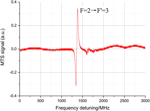
FIGURE 14. The scanned MTS signal of 87Rb D2 line.

FIGURE 15. The frequency stability of IF-ECDL with MTS.
By positioning a PD to monitor the diffraction light produced by the AOM, the stabilized laser light is achieved. Here the PD is home-built, whose gain is 1.8 × 10⁵V/W and the maximum output voltage is 5 V. Using this PD, the intensity stability of the monitored laser is shown in Figure 16. The intensity stability of 4 × 10⁻⁵
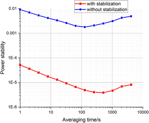
FIGURE 16. The intensity stability of the monitored laser with and without stabilization.
The optical lattice that shifts from the focused laser beam red-detuned about 72 nm below an atomic dipole resonance using the ac Stark, is designed to trap the 87Rb cold atoms. The cold atoms in ground state F = 2 can be trapped when the optical lattice laser is turned on. The lifetime of cold atoms in the trap will be determined by the interactions of the cold atoms with photons, and the collisions with other atoms [40]. During the interaction between the cold atoms with light, an atom will absorb a photon and emits a photon spontaneously. The direction of the emitted photon and the recoil momentum of atoms are random, which will cause the heating rate due to the momentum diffusion. When the accumulated collision between cold atoms and background gas atoms exceeds the potential well depth, the cold atoms will escape from the well and the lifetime will be limited. In addition, the accumulated heating caused by the fluctuation of potential well depth can raise the temperature of the cold atoms. Once the temperature of the cold atoms exceeds the optical depth, the cold atoms will also escape from the well.
Although the heating rate due to the momentum diffusion may be small at large detuning, the diffusive heating always introduces an upper limit on the lifetime. As described in Section 3.3, the detuning
where
where
The optical lattice is performed in a vacuum tube attached to an ion pump. The lifetime of cold atoms in the trap is also limited by the collisions with other atoms. The lifetime limited by the collisions
It is assumed that the collision cross section
When the cold atoms are trapped in a noisy optical lattice, we have to consider the heating rate caused by the fluctuation of optical lattice laser power and polarization. The fluctuation of potential well depth arises naturally due to the fluctuations of the optical lattice laser, which is time-dependent. The accumulated heating caused by the fluctuation of potential well depth can raise the temperature of the cold atoms. Once the temperature of the cold atoms exceeds the optical depth, the cold atoms will also escape from the well and the lifetime will be limited. The heating process caused by the fluctuation of optical lattice laser power and polarization is related to the noise spectrum and the many-body dynamics. Here, we ignore the lifetime limited by the fluctuations of optical lattice laser, and it will be studied in the future.
The potential in the optical lattice can be approximated by the harmonic trap in both the longitudinal and radial dimensions yielding the vibrational frequencies. The theoretical calculation formulas of the longitudinal
To determine the stabilized laser system and optical lattice contributions, the frequency stability is calculated by the Ramsey spectroscopy. We present the frequency stability of
where
In conclusion, the construction of the optical system in the atomic clock-beyond atomic fountain based on 87Rb atom is investigated. By optimizing the laser frequency locking and shift, we demonstrate the stabilized and simple laser system for laser cooling. The frequency and intensity stability are achieved to 4 × 10–14
The original contributions presented in the study are included in the article/Supplementary Material, further inquiries can be directed to the corresponding authors.
XW, JH, YWe, and LG developed the principle, designed the Experimental set-up and wrote the manuscript; YiW, YuW, WW (5th author), WW (6th author), SLi, XZ, GL, SLiu, and YeW carried out the experiments and tests; YYu and GH analyzed the calculation data; ZL and YP analyzed the spectroscopy and data; LW, YL, TY, and CC revised the manuscript.
This work was funded by the Fundamental Research Project of Shenzhen Sci. & Tech. Fund (JCYJ20210324115812036, JCYJ20200109144612399, JCYJ20200109144601715), 2021Szvup002, IERF202002 and IERF202105.
We give our best wishes to Prof. Yiqiu Wang and congratulate him on his achievements in quantum precision measurement and cold atom physics on the occasion of his 90th birthday. We are also grateful to Yige Lin and Qiang Wang (National Institute of Metrology, China) for fruitful discussions in this paper.
ZL and YP were employed by Zhejiang Faraday Laser Technology Co.,Ltd.
The remaining authors declare that the research was conducted in the absence of any commercial or financial relationships that could be construed as a potential conflict of interest.
All claims expressed in this article are solely those of the authors and do not necessarily represent those of their affiliated organizations, or those of the publisher, the editors and the reviewers. Any product that may be evaluated in this article, or claim that may be made by its manufacturer, is not guaranteed or endorsed by the publisher.
1. Gibble K, Chu S. Laser-cooled Cs frequency standard and a measurement of the frequency shift due to ultracold collisions. Phys Rev Lett (1993) 70:1771–4. doi:10.1103/physrevlett.70.1771
2. Santarelli G, Laurent P, Lemonde P, Clairon A, Mann AG, Chang S, et al. Quantum projection noise in an atomic fountain: A high stability cesium frequency standard. Phys Rev Lett (1999) 82:4619–22. doi:10.1103/physrevlett.82.4619
3. Liu L, Lü DS, Chen WB, Li T, Qu QZ, Wang B, et al. In-orbit operation of an atomic clock based on laser-cooled 87Rb atoms. Nat Commun (2018) 9:2706. doi:10.1038/s41467-018-05219-z
4. Liu P, Meng YL, Wan JY, Wang XM, Wang YN, Xiao L, et al. Scheme for a compact cold-atom clock based on diffuse laser cooling in a cylindrical cavity. Phys Rev A (2015) 92:062101. doi:10.1103/physreva.92.062101
5. Nicholson TL, Campbell SL, Hutson RB, Marti GE, Bloom BJ, McNally RL, et al. Systematic evaluation of an atomic clock at 2 × 10⁻¹⁸ total uncertainty. Nat Commun (2015) 6:6896. doi:10.1038/ncomms7896
6. Hardman KS, Kuhn CCN, McDonald GD, Debs JE, Bennetts S, Close JD, et al. Role of source coherence in atom interferometry. Phys Rev A (2014) 89:023626. doi:10.1103/physreva.89.023626
7. Peters A, Chung KY, Chu S. Measurement of gravitational acceleration by dropping atoms. Nature (1999) 400:849–52. doi:10.1038/23655
8. Gustavson TL, Bouyer P, Kasevich MA. Precision Rotation Measurements with an atom interferometer gyroscope. Phys Rev Lett (1997) 78:2046–9. doi:10.1103/physrevlett.78.2046
10. Anderson MH, Ensher JR, Matthews MR, Wieman CE, Cornell EA. Observation of Bose-Einstein condensation in a dilute atomic vapor. Science (1995) 269:198–201. doi:10.1126/science.269.5221.198
11. Davis KB, Mewes MO, Andrews MR, van Druten NJ, Durfee DS, Kurn DM, et al. Bose-Einstein condensation in a gas of Sodium atoms. Phys Rev Lett (1995) 75:3969–73. doi:10.1103/physrevlett.75.3969
12. Monroe C. Quantum information processing with atoms and photons. Nature (2002) 416:238–46. doi:10.1038/416238a
13. Duan LM, Lukin MD, Cirac JI, Zoller P. Long-distance quantum communication with atomic ensembles and linear optics. Nature (2001) 414:413–8. doi:10.1038/35106500
14. Wynands R, Weyers S. Atomic fountain clocks. Metrologia (2005) 42:S64–S79. doi:10.1088/0026-1394/42/3/s08
15. Takekoshi T, Knize RJ. CO_2 laser trap for cesium atoms. Opt Lett (1996) 21:77–9. doi:10.1364/ol.21.000077
16. O’Hara KM, Granade SR, Gehm ME, Savard TA, Bali S, Freed C, et al. Ultrastable CO2 laser trapping of lithium Fermions. Phys Rev Lett (1999) 82:4204–7.
17. Chen JB, Zhou XJ, Chen XZ. Beyond fountain. Miami, FL: Institute of Electrical and Electronics Engineers (2006). 281–3.
18. Zhou XJ, Chen XZ, Chen JB, Wang YQ, Li JM. Microwave atomic clock in the optical lattice with specific fre quency. Chin Phys Lett (2009) 26:090601. doi:10.1088/0256-307X/26/9/090601
19. Beloy K, Derevianko A, Dzuba VA, Flambaum VV. Micromagic clock: Microwave clock based on atoms in an engineered optical lattice. Phys Rev Lett (2009) 102:120801. doi:10.1103/physrevlett.102.120801
20. Derevianko A. "Doubly magic" conditions in magic-wavelength trapping of ultracold alkali-metal atoms. Phys Rev Lett (2010) 105:033002. doi:10.1103/PhysRevLett.105.033002
21. Chicireanu R, Nelson KD, Olmschenk S, Lundblad N, Derevianko A, Porto JV. Differential light-shift cancellation in a magnetic-field-insensitive transition of 87rb. Phys Rev Lett (2011) 106:063002. doi:10.1103/PhysRevLett.106.063002
22. Lundblad N, Schlosser M, Porto JV. Experimental observation of magic-wavelength behavior of 87Rb atoms in an optical lattice. Phys Rev A (2010) 81:031611. doi:10.1103/physreva.81.049904
23. Campbell SL, Hutson RB, Marti GE, Goban A, Darkwah Oppong ND, McNally RL, et al. A Fermi-degenerate three-dimensional optical lattice clock. Science (2017) 358:90–4. doi:10.1126/science.aam5538
24. Li X, Li XP, Sarma SD. Mobility edges in one-dimensional bichromatic incommensurate potentials. Phys Rev B (2017) 96:085119. doi:10.1103/physrevb.96.085119
25. Lüschen HP, Scherg S, Kohlert T, Schreiber M, Bordia P, Li X, et al. Single-particle mobility edge in a one-dimensional quasiperiodic optical lattice. Phys Rev Lett (2018) 120:160404. doi:10.1103/PhysRevLett.120.160404
26. Blatt S, Thomsen JW, Campbell GK, Ludlow AD, Swallows MD, Martin MJ, et al. Rabi spectroscopy and excitation inhomogeneity in a one-dimensional optical lattice clock. Phys Rev A (2009) 80:052703. doi:10.1103/physreva.80.052703
27. Fang F, Chen WL, Liu K, Liu NF, Suo R, Li TC. Design of the new NIM6 fountain with collecting atoms from a 3D MOT loading optical molasses. IEEE Int Frequency Control Symp (2015) 2015:492–4. doi:10.1109/fcs.2015.7138891
28. Fang F, Li MS, Lin PW, Chen WL, Liu NF, Lin YG, et al. NIM5 Cs fountain clock and its evaluation. Metrologia (2015) 52:454–68. doi:10.1088/0026-1394/52/4/454
29. Corwin KL, Lu ZT, Hand CF, Epstein RJ, Wieman CE. Frequency-stabilized diode laser with the Zeeman shift in an atomic vapor. Appl Opt (1998) 37:3295–8. doi:10.1364/ao.37.003295
30. Wieman C, Hänsch TW. Doppler-free laser polarization spectroscopy. Phys Rev Lett (1976) 36:1170–3. doi:10.1103/physrevlett.36.1170
31. Bjorklund GC. Frequency-modulation spectroscopy: A new method for measuring weak absorptions and dispersions. Opt Lett (1980) 5:15–7. doi:10.1364/ol.5.000015
32. Black ED. An introduction to Pound-Drever-Hall laser frequency stabilization. Am J Phys (2001) 69:79–87. doi:10.1119/1.1286663
33. Preston DW. Doppler‐free saturated absorption: Laser spectroscopy. Am J Phys (1996) 64:1432–6. doi:10.1119/1.18457
34. Shirley JH. Modulation transfer processes in optical heterodyne saturation spectroscopy. Opt Lett (1982) 7:537–9. doi:10.1364/ol.7.000537
35. Baillard X, Gauguet A, Bize S, Lemonde P, Laurent P, Clairon A, et al. Interference-filter-stabilized external-cavity diode lasers. Opt Commun (2006) 266:609–13. doi:10.1016/j.optcom.2006.05.011
36. Jiang ZJ, Zhou Q, Tao ZM, Zhang XG, Zhang SN, Zhu CW, et al. Diode laser using narrow bandwidth interference filter at 852 nm and its application in faraday anomalous dispersion optical filter. Chin Phys. B (2016) 25:083201. doi:10.1088/1674-1056/25/8/083201
37. Qi XH, Chen WL, Lin Y, Zhou DW, Zhou T, Xiao Q, et al. Ultra-stable rubidium-stabilized external-cavity diode laser based on the modulation transfer spectroscopy technique. Chin Phys Lett (2009) 26:044205. doi:10.1088/0256-307X/26/4/044205
38. Tricot F, Phung M, Lours S, Guérandel ED, de Clercq E. Power stabilization of a diode laser with an acousto-optic modulator. Rev Scientific Instr (2018) 89:113112. doi:10.1063/1.5046852
39. Wei Chun-Hua CH, Yan Shu-Hua SH, Yang Jun J, Wang Guo-Chao GC, Jia Ai-Ai AA, Luo Yu-Kun YK, et al. Design and control of large-detuned optical lattice based on 87Rb atoms. Acta Phys Sin (2017) 66:010701. doi:10.7498/aps.66.010701
Keywords: laser cooling, cold atom, laser stabilization, optical lattice, atomic fountain clock
Citation: Wang X, He J, Wang Y, Wang Y, Wang W, Wang W, Li S, Zhu X, Liu G, Liu S, Wang Y, Wang L, Liu Y, Yang T, Cao C, Wei Y, Yue Y, Hu G, Liu Z, Pan Y and Gao L (2022) Construction of optical system for an atomic clock-beyond atomic fountain. Front. Phys. 10:971099. doi: 10.3389/fphy.2022.971099
Received: 16 June 2022; Accepted: 22 July 2022;
Published: 25 August 2022.
Edited by:
Xuzong Chen, Peking University, ChinaReviewed by:
Kaikai Huang, Zhejiang University, ChinaCopyright © 2022 Wang, He, Wang, Wang, Wang, Wang, Li, Zhu, Liu, Liu, Wang, Wang, Liu, Yang, Cao, Wei, Yue, Hu, Liu, Pan and Gao. This is an open-access article distributed under the terms of the Creative Commons Attribution License (CC BY). The use, distribution or reproduction in other forums is permitted, provided the original author(s) and the copyright owner(s) are credited and that the original publication in this journal is cited, in accordance with accepted academic practice. No use, distribution or reproduction is permitted which does not comply with these terms.
*Correspondence: Jin He, ZnJhbmtoZUBwa3UuZWR1LmNu; Yiqun Wei, d2VpeXFAaWVyLm9yZy5jbg==; Lianshan Gao, Z2FvbGlhbnNoYW4yNThAMTI2LmNvbQ==
Disclaimer: All claims expressed in this article are solely those of the authors and do not necessarily represent those of their affiliated organizations, or those of the publisher, the editors and the reviewers. Any product that may be evaluated in this article or claim that may be made by its manufacturer is not guaranteed or endorsed by the publisher.
Research integrity at Frontiers
Learn more about the work of our research integrity team to safeguard the quality of each article we publish.