 Danjie Yin
 Kaijun Yi
 Zhiyuan Liu1
 Rui Zhu
- 1School of Aerospace Engineering, Beijing Institute of Technology, Beijing, China
- 2Wuhan Second Ship Design and Research Institute, Wuhan, China
Thin-walled cylindrical shells are widely used in industries, such as the main parts of aircrafts, rockets, and submarines. Except for meeting the load-bearing capacities, such structures must also have good vibration and acoustic performances. However, it is still a challenge to control the multi-modal vibration of cylindrical shells at low frequencies. This study explores the cutting-edge local resonant piezoelectric metamaterials to control the low-frequency vibration of cylindrical shells. A novel cylindrical meta-shell with piezoelectric materials and digital circuits was proposed, and a multi-resonance transfer function is implemented in each digital circuit. A method to optimizing the parameters in the transfer function for the purpose of vibration reduction is developed. The vibrational characteristics of the meta-shell are numerically analyzed using the finite element method. Numerical results clearly demonstrate that by delicately designing the parameters in the transfer function, the meta-shell can reduce the peak amplitudes of the first five modes by 30 dB or more. Therefore, the proposed piezoelectric cylindrical meta-shell may open new opportunities in vibration mitigation of transport vehicles and underwater equipment.
1 Introduction
Thin-walled cylindrical shells are widely used in industries, for example, the main parts of aircrafts, rockets, and submarines are all made of cylindrical shells. The radiation noise generated by the vibrating cylindrical shells may harm precise equipment inside the aircrafts, and even cause fatigue failure of structures [1]. As a result, cylindrical shells must have good vibration and acoustic performances while meeting static bearing capacity. To fulfill such demands, many methods have been proposed to reduce the vibration and the corresponding radiation noise of cylindrical shells. Boily et al [2] investigated the impact of viscoelastic and porous materials on vibration and noise reduction of cylindrical shells. Ji et al [3] proposed a method to control the vibration of pipelines by using magneto-rheological (MR) vibration reduction technology. Zhang [4] proposed to control the vibration of the cylindrical shell by periodically or non-periodically–attached dynamic vibration absorber (DVA). In addition to damping and absorbing vibration, there are also vibration control methods. Wang et al [5] investigated the vibration isolation effects of a blocking mass on a double-layer cylindrical shell and demonstrated that it can effectively prevent the transmission of vibration waves. Huang et al [6] used a numerical model to investigate the vibration transmission from vibrating machinery to the cylindrical shell structure through the active vibration isolators. In order to improve the performances and effects of viscoelastic damping layers, Baz et al [7] proposed the concept of an actively constrained damping layer. Ray et al [8] arranged the actively constrained damping layers on a large-scale cylindrical shell, and optimized the parameters and positions of the damping layer to realize good vibration reduction effects. However, the aforementioned methods and many others only have good effects at middle or high frequencies; controlling low-frequency vibration of cylinder shells is still a huge challenge.
During the last decades, the emerged elastic metamaterials provide possibility to dealing with the low-frequency vibration. Such manmade materials show bandgaps at low frequencies generated by local resonators. The elastic metamaterial with local resonators is first proposed by Liu et al [9] in 2000. After that, researchers studied the unprecedented properties of metamaterials, such as negative mass density [10–12], negative modulus [13, 14], and even simultaneous negative density and modulus [15, 16]. From the perspective of materials, bandgaps are the consequences of negative effective parameters. Within these bandgaps, propagation of elastic waves is prohibited. Consequently, the vibration of structures made by metamaterials is significantly reduced. Chen et al [17] proposed the addition of local resonators into a sandwich beam and studied the bandgap effects in this metamaterial beam, results show the waves are significantly attenuated. Claeys et al [18] designed a local resonant metamaterial plate and investigated the noise radiation properties within the bandgaps, good vibroacoustic behaviors of this plate are observed. Jung et al [19] explored the use of metamaterials to reduce the low-frequency noise radiation of an automobile dash panel structure, numerical and experimental results verified the idea. Recently, metamaterials are also used in shell structures. Droz et al [20] mounted local resonators on a curved panel to enhance the sound transmission loss at the ring frequency. Jin et al [21] designed a metamaterial cylindrical shell by introducing local resonators into unit cells of a traditional cylindrical honeycomb sandwich structure, and they studied the bandgap phenomena in such metastructures and found that within the bandgaps, vibration of the cylinder shell is considerably mitigated. It should be noted that metamaterials usually suffer the drawback of narrow sizes. To broaden the bandgaps, metamaterials with multiple resonators in a single unit cell [22–26] or gradually varying in space [27, 28] were proposed and studied. The working frequency regions of these metamaterials are enlarged to some extent, however, at the cost of adding considerable extra mass. In summary, even though metamaterials with local resonators are promising candidates for reducing low-frequency vibration, they either have narrow working frequencies or would add too much mass into the original systems, which makes them unsuitable to control multi-modal resonances of thin-walled cylindrical shells at low frequencies.
In addition to the previously introduced metamaterials, which are composed of passive mechanical local resonators, piezoelectric metamaterials based on resonant shunts are also widely studied. These so-called local resonant piezoelectric metamaterials (LRPMs) generate bandgaps via piezoelectric materials and electronic resonators. Throp et al [29] first proposed to periodically distribute piezoelectric patches with resonant shunts on a rod and observed bandgaps induced by shunts. Spadoni et al [30] extended this concept to two-dimensional structures and developed piezoelectric metamaterial plates. Csadei et al [31] designed a method to predict the attenuation properties of the periodically assembled unit cells, and verified it experimentally. Furthermore, Airoldi and Ruzzene [32] studied a beam with periodically shunted piezoelectric patches, and they found that the equivalent stiffness of the metamaterial beam is significantly affected by circuit parameters and has resonance characteristics near the circuit resonant frequency, leading to bandgaps. Therefore, from the perspective of metamaterials, periodical piezostructures with resonant shunts are new types of metamaterials. To broaden the overall bandgap size, Sugino et al [33] proposed a transfer function to realize multiple resonances in a piezoelectric metamaterial beam. Wang et al [34] designed digital circuits using separated patches as sensors and actuator to realize multiple resonances in a piezoelectric metamaterial beam. However, these multi-resonant metamaterials are limited to beam structures. Recently, Yi et al [35] developed a general method to design multi-resonant piezoelectric metamaterials based on digital circuits, multiple bandgaps and the wave isolation effects are demonstrated using a plate structure. Theoretically, the method developed in [35] can be expanded to design any type of multi-resonant metamaterial structures, including cylindrical shells, which gives a new possibility to control broadband low-frequency vibration of such complex structures.
In this study, a novel cylindrical meta-shell is designed based on piezoelectric materials and digital circuits. A transfer function to realize multi-resonance developed by the authors in [35] is implemented in the digital circuit. A method was developed to optimizing the transfer function for realizing the best vibration reduction effects at low frequencies. The vibration characteristics of such metashells are numerically studied, and multi-modal vibration reduction effects are clearly demonstrated. The rest of this study is organized as follows: Section 2 introduces the conception and major components of the meta-shell with piezoelectric patches and digital circuits; in Section 3, a reduced and corrected model is developed to efficiently calculate the forced response of piezoelectric metashells; an algorithm to optimize the parameters in the transfer function is proposed in Section 4; Section 5 verifies the excellent multi-modal vibration reduction performances at low frequencies; finally, Section 6 presents conclusions of this work.
2 Cylindrical meta-shell with piezoelectric materials and digital circuits
In this section, the model of the studied cylindrical meta-shell with piezoelectric materials and digital circuits is presented. Such a meta-shell is composed of four main parts: (I) a host passive shell structure, (II) piezoelectric patches distributed on the outer surface of the host shell, (III) digital circuits connecting to the patches, and (IV) a suitable transfer function implemented in the digital circuit.
2.1 Mechanical parts of the piezoelectric cylindrical meta-shell
As shown in Figure 1A, the presented meta-shell is composed of a host structure covered with piezoelectric patches periodically distributed on the outer surface of the host structure. The polarization of the patches is along the normal direction. The thickness of piezoelectric patches is
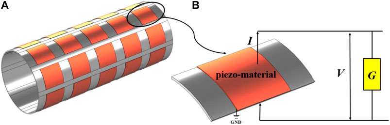
FIGURE 1. (A) Physical model of the cylindrical meta-shell with piezoelectric patches and digital circuits, (B) a unit-cell of the meta-shell,
TABLE 1. Material and geometry parameters of the meta-shell.
2.2 The transfer function to generate multiple resonances
The transfer function proposed by the authors in [35] is used to generate multiple resonances. It is expressed as:
Here,
Therefore, we can set the transfer function’s zeros
It is well demonstrated in [35] that the transfer function
3 Reduced model for calculating dynamic responses of the piezoelectric cylindrical meta-shell
This section develops a reduced model to efficiently calculate the vibration responses of the cylindrical piezoelectric meta-shell. The reduced model is obtained in three steps. First, the piezoelectric meta-shell is modeled using the finite element method. Second, the whole model is reduced using the modal synthesis method. Last, the reduced model is corrected through the modification of the intrinsic capacitances of the patches.
The equilibrium equations for the discretized fully coupled piezoelectric system are [36]:
Here,
The reduced model is obtained through a transformation between the displacement d and a set of modal coordinates q.
Here,
Here,
Here, E is the identity matrix. Using Eqs 5, 7, 8, the governing Eq. 4 is represented in modal coordinates as:
Only a few modes in modal matrix
However, the reduced model in Eq. 9 cannot adequately capture the system’s piezoelectric behaviors because the truncation of the higher-order modes will cause a static reduction error [36]. The static error will result in a non-negligible electrostatic voltage error when compared to the full model, it is as follows:
Here,
The reduced model is corrected by modifying the blocked intrinsic capacitance matrix C to produce more accurate voltage responses. The voltage responses are corrected by ensuring that the voltage outputs V(i) of the ith piezoelectric patch in the corrected reduced model and the full model are consistent when the same static electric input Q(i) is applied to this patch. According to Eqs 4, 9, such requirements are fulfilled by modifying the capacitance matrix
The reduced model obtains an excellent accuracy after error correction and improves computational efficiency, and it provides an efficient tool to calculate the dynamic responses of the piezoelectric meta-shell, which is a very important step in the optimization algorithm developed in Section 4.
4 Optimization method for the parameters in the transfer function
For the transfer function in Eq. 1,
As analyzed in [35], if a transfer function contains n poles and these poles are well separated, they have negligible influences on each other, which means that the values of
When the target modes are selected, we can determine the number of poles n needed in the transfer function. The values of
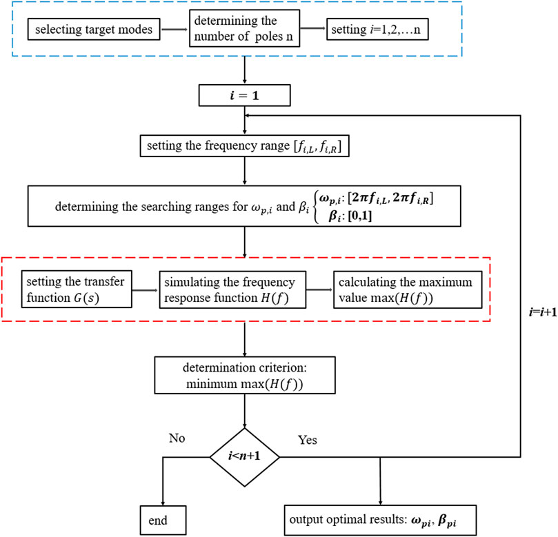
FIGURE 2. Flow chart of the optimization algorithm to calculate the optimal electrical parameters.
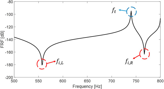
FIGURE 3. Example to show the left and right anti-resonance frequencies
5 Numerical verification of multi-modal vibration reduction of piezoelectric cylindrical meta-shell
In this section, the multi-modal vibration reduction effects of piezoelectric cylindrical meta-shell are numerically verified. Figure 4 shows the finite element model of the studied piezoelectric meta-shell. There are 8∗5 = 40 piezoelectric patches glued on the surface of the passive shell. The geometry and material parameters of the cylindrical piezoelectric meta-shell are the same as those in Table 1. The convergence of the model is verified; refining the meshes to double the number of DOFs only changes the calculated natural frequencies of the first 10 modes by less than 0.2%. A harmonic load F is applied at point O to mimic a source of disturbance.
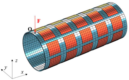
FIGURE 4. Finite element model of a piezoelectric cylindrical meta-shell.
5.1 Level of mean square normal velocity of cylindrical shells
The level of mean square normal velocity (MSNV) of the meta-shell is used to evaluate the vibration reduction performances. The cylindrical coordinate system and the degrees of freedom are depicted in Figure 5,
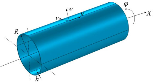
FIGURE 5. Schematic diagram of the shell coordinate system.
Since the thickness of the shell is much smaller than the radius of it, we can assume that the normal velocity does not change along the radial direction. Therefore, the MSNV of the shell is calculated by only considering the points on the outer surface of the shell, and the expression of it is as follows [37]:
Here,
The level of MSNV is defined as [37]:
Here, the velocity reference
5.2 Verification of the multi-modal vibration control effects
To demonstrate the vibration reduction effects of the cylindrical piezoelectric meta-shell, three cases are studied targeting different resonant modes. In case 1, the targeted modes are the first two, since the frequencies of the first and second modes are very close, a one-pole transfer function is designed. In case 2, they are the first four modes, the third and fourth modes are also very close, one single pole can be used to control them, therefore, in this case, a two-pole transfer function is used. In case 3, we target all the first five modes and a three-pole transfer function is used to control.
First of all, the optimal values in the transfer function for each case are designed using the optimization method developed in Section 4. The frequency response function at point O (Figure 4) is used in the process of optimization, and it is calculated by dividing the amplitude of the normal displacement of point O by the amplitude of the excitation force at the same point. Here, we used case 3 as an example to show how the optimum values are determined. In this case, a 3-pole transfer function is used, results in Figure 6 illustrate the influences of
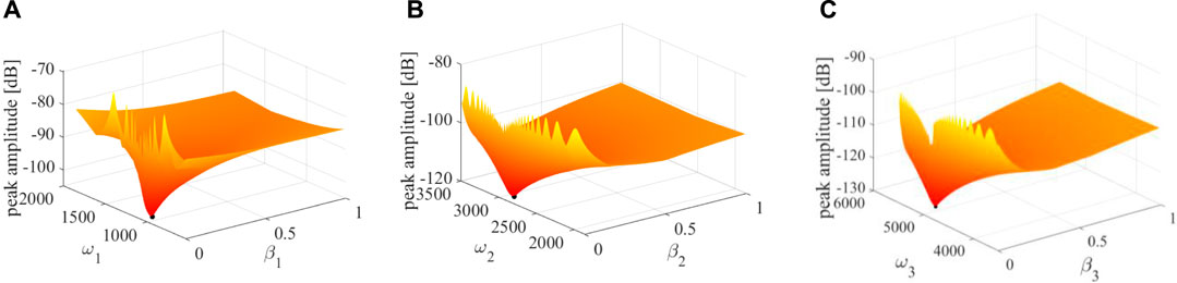
FIGURE 6. Influences of
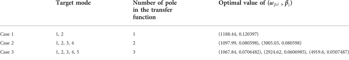
TABLE 2. Optimum parameters of the transfer functions used in different cases.
Figure 7 shows the vibration reduction effects for the three different cases calculated using the finite element model. In each case, the level of MSNV of the shell at short-circuited condition is used as a reference, it is the uncontrolled case. First, take the first two modes as the target to reduce vibration, Figure 7A shows that the peak of frequency response curves in the 1-pole case decreased by an average of 32 dB compared to the case without control. Second, in case two, the first four modes are targeted, and all the peak amplitudes, in this case, are reduced by more than 30 dB, as shown in Figure 7B. Finally, when aiming at the first five modes, as shown in Figure 7C, the amplitudes of all the peaks are reduced by about 30 dB. In summary, the cases studied earlier clearly verify that the meta-shell proposed in this work can achieve excellent multi-modal vibration reduction effects at low frequencies.
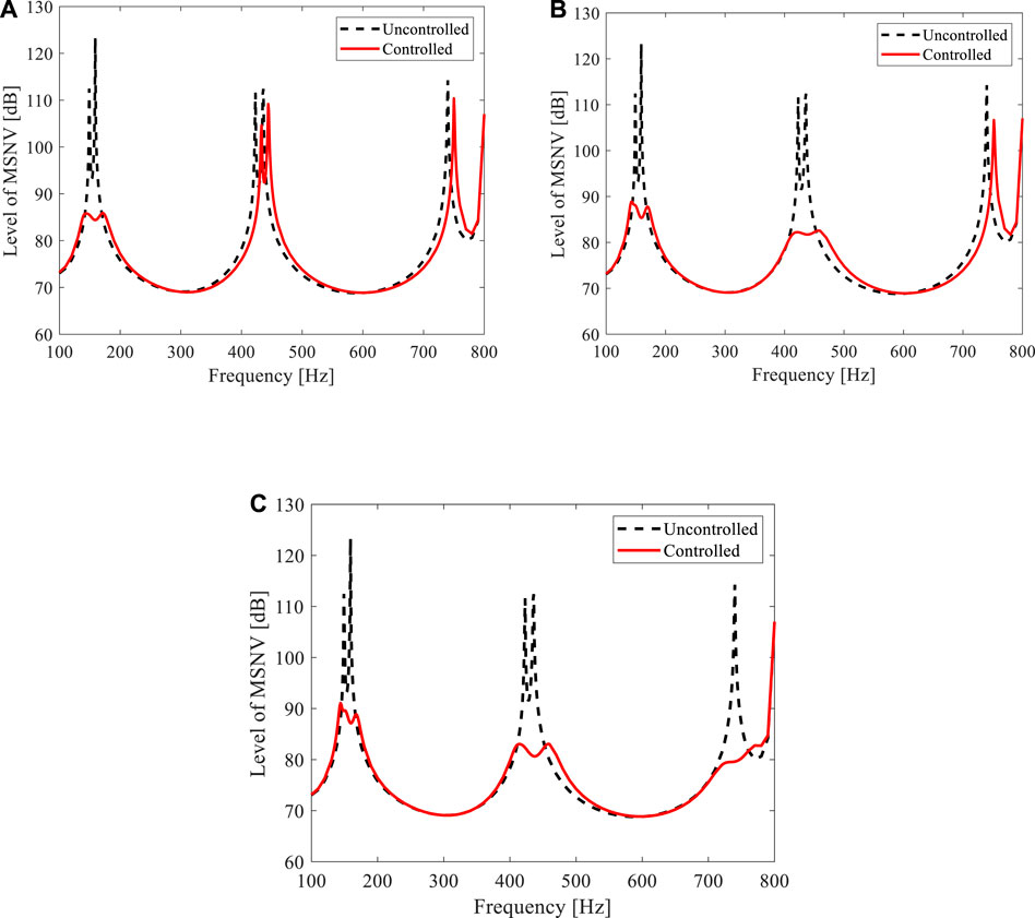
FIGURE 7. Frequency response curves of level of MSNV of the piezoelectric cylindrical meta-shell with different optimized transfer functions. The first (A) two, (B) four, and (C) five modes are targeted, respectively.
6 Conclusion
In this study, a cylindrical meta-shell with piezoelectric materials and digital circuits is designed, and the multi-modal vibration reduction effects of it are demonstrated. The mechanical parts of the meta-shell include a host cylindrical shell, piezoelectric patches distributed on the outer surface of the shell, and digital circuits shunted to the patches. A suitable transfer function is implemented in the digital circuit to generate multiple resonances. To analyze the dynamic responses of the designed piezoelectric cylindrical meta-shell, a reduced model is obtained based on the modal truncation technique and the accuracy of it is corrected by modifying intrinsic capacitances of the patches. An optimization algorithm is developed to design the optimum parameters in the transfer function for the purpose of vibration reduction. Finally, cases are studied to verify the multi-modal vibration reduction abilities of the meta-shell. The results clearly demonstrate that by designing the parameters of the transfer function, multi-modal vibration reduction effects can be achieved for desired resonant modes, the peak magnitudes of these modes are suppressed by more than 30 dB. Therefore, this novel piezoelectric cylindrical meta-shell could open new opportunities in vibration mitigation of transport vehicles and underwater equipment.
Data availability statement
The original contributions presented in the study are included in the article/Supplementary Material; further inquiries can be directed to the corresponding author.
Author contributions
DY: writing—original draft, methodology, software, data curation, editing, visualization, and investigation. KY: conceptualization, writing and review of the manuscript, structural scheme design, and theoretical model analysis, supervision, funding acquisition. ZL: methodology. AZ: investigation. RZ: investigation.
Funding
This work is supported by the National Natural Science Foundation of China (Nos. 11991030, 11991031, and 11872112), National Key Research and Development Program of China (2021YFE0110900), and Innovation Foundation of Maritime Defense Technologies Innovation Center (No. JJ-2020-719-05).
Conflict of interest
The authors declare that the research was conducted in the absence of any commercial or financial relationships that could be construed as a potential conflict of interest.
Publisher’s note
All claims expressed in this article are solely those of the authors and do not necessarily represent those of their affiliated organizations, or those of the publisher, the editors, and the reviewers. Any product that may be evaluated in this article, or claim that may be made by its manufacturer, is not guaranteed or endorsed by the publisher.
References
1. Goldman RL. Mode shapes and frequencies of clamped-clamped cylindrical shells. AIAA J (1974) 12(12):1755–6. doi:10.2514/3.49599
2. Boily S, Charron F. The vibroacoustic response of a cylindrical shell structure with viscoelastic and poroelastic materials. Appl Acoust (1999) 58(2):131–52. doi:10.1016/s0003-682x(98)00070-x
3. Ji H, Huang Y, Nie S, Yin F, Dai Z. Research on semi-active vibration control of pipeline based on magneto-rheological damper. Appl Sci (2020) 10(7):2541. doi:10.3390/app10072541
4. Zhang JJ. The optimization analysis on the vibration control of cylindrical shell with dynamic vibration absorber attached. Vibroengineering Proced (2018) 20:5–10. doi:10.21595/vp.2018.20093
5. Wang XZ, Sun LQ, Yao XL, Isolation characteristics of cylindrical shell with blocking mass bass[J]. Huazhong Univ Sci Tech (2012) 40:50–3. doi:10.1007/978-3-540-76833-3_309
6. Huang XC, Zhang ZY, Zhang ZH, Hongxing H. Multi-channel active vibration isolation for the control of underwater sound radiation from A stiffened cylindrical structure: A numerical study. J Vib Acoust (2012) 134(1):011012. doi:10.1115/1.4004684
7. Baz AM, Ro JJ. The concept and performance of active constrained layer damping treatments[J]. Sound and Vibration (1994) 28(3):18–21. doi:10.1006/jsvi.2001.4196
8. Ray MC, Baz A. Optimization of energy dissipation of active constrained layer damping treatments of plates[J]. J Sound Vibration (1997) 208(3):391–406. doi:10.1006/jsvi.1997.1171
9. Liu Z, Zhang X, Mao Y, Zhu YY, Yang Z, Chan CT, et al. Locally resonant sonic materials. Science (2000) 289(5485):1734–6. doi:10.1126/science.289.5485.1734
10. Yao S, Zhou X, Hu G. Experimental study on negative effective mass in a 1D mass–spring system. New J Phys (2008) 10(4):043020. doi:10.1088/1367-2630/10/4/043020
11. Huang HH, Sun CT. Wave attenuation mechanism in an acoustic metamaterial with negative effective mass density. New J Phys (2009) 11(1):013003. doi:10.1088/1367-2630/11/1/013003
12. Huang HH, Sun CT, Huang GL. On the negative effective mass density in acoustic metamaterials. Int J Eng Sci (2009) 47(4):610–7. doi:10.1016/j.ijengsci.2008.12.007
13. Fang N, Xi D, Xu J, Ambati M, Srituravanich W, Sun C, et al. Ultrasonic metamaterials with negative modulus. Nat Mater (2006) 5(6):452–6. doi:10.1038/nmat1644
14. Zhou X, Hu G. Analytic model of elastic metamaterials with local resonances. Phys Rev B (2009) 79(19):195109. doi:10.1103/physrevb.79.195109
15. Liu XN, Hu GK, Huang GL, Sun CT. An elastic metamaterial with simultaneously negative mass density and bulk modulus. Appl Phys Lett (2011) 98(25):251907. doi:10.1063/1.3597651
16. Zhu R, Liu XN, Hu GK, Sun CT, Huang GL. Negative refraction of elastic waves at the deep-subwavelength scale in a single-phase metamaterial. Nat Commun (2014) 5(1):5510. doi:10.1038/ncomms6510
17. Chen JS, Sharma B, Sun CT. Dynamic behaviour of sandwich structure containing spring-mass resonators. Compos Structures (2011) 93(8):2120–5. doi:10.1016/j.compstruct.2011.02.007
18. Claeys CC, Sas P, Desmet W. On the acoustic radiation efficiency of local resonance based stop band materials. J Sound Vibration (2014) 333(14):3203–13. doi:10.1016/j.jsv.2014.03.019
19. Jung J, Kim HG, Goo S, Chang KJ, Wang S. Realisation of a locally resonant metamaterial on the automobile panel structure to reduce noise radiation. Mech Syst Signal Process (2019) 122:206–31. doi:10.1016/j.ymssp.2018.11.050
20. Droz C, Robin O, Ichchou M, Atalla N. Improving sound transmission loss at ring frequency of a curved panel using tunable 3D-printed small-scale resonators. The J Acoust Soc America (2019) 145(1):EL72–8. doi:10.1121/1.5088036
21. Jin Y, Jia XY, Wu QQ, Yu GC, Zhang XL, Chen S, et al. Design of cylindrical honeycomb sandwich meta-structures for vibration suppression. Mech Syst Signal Process (2022) 163:108075. doi:10.1016/j.ymssp.2021.108075
22. Huang GL, Sun CT. Band gaps in a multiresonator acoustic metamaterial. J Vib Acoust (2010) 132(3):031003. doi:10.1115/1.4000784
23. Zhu R, Huang GL, Hu GK. Effective dynamic properties and multi-resonant design of acoustic metamaterials. J Vib Acoust (2012) 134(3):031006. doi:10.1115/1.4005825
24. Chen YY, Barnhart MV, Chen JK, Hu G, Sun C, Huang G. Dissipative elastic metamaterials for broadband wave mitigation at subwavelength scale. Compos Structures (2016) 136:358–71. doi:10.1016/j.compstruct.2015.09.048
25. Barnhart MV, Xu X, Chen Y, Zhang S, Song J, Huang G. Experimental demonstration of a dissipative multi-resonator metamaterial for broadband elastic wave attenuation. J Sound Vibration (2019) 438:1–12. doi:10.1016/j.jsv.2018.08.035
26. Gorshkov V, Sareh P, Navadeh N, Tereshchuk V, Fallah AS. Multi-resonator metamaterials as multi-band metastructures. Mater Des (2021) 202:109522. doi:10.1016/j.matdes.2021.109522
27. Meng H, Chronopoulos D, Fabro AT, Elmadih W, Maskery I. Corrigendum to “Rainbow metamaterials for broadband multi-frequency vibration attenuation: Numerical analysis and experimental validation” [J. Sound Vib. (2020) 115005]. J Sound Vibration (2020) 465:115577. doi:10.1016/j.jsv.2020.115577
28. Meng H, Elmadih W, Jiang H, Lawrie T, Chen Y, Chronopoulos D. Broadband vibration attenuation achieved by additively manufactured 3D rainbow hollow sphere foams. Appl Phys Lett (2021) 119(18):181901. doi:10.1063/5.0069801
29. Thorp O, Ruzzene M, Baz A. Attenuation and localization of wave propagation in rods with periodic shunted piezoelectric patches. Smart Mater Struct (2001) 10(5):979–89. doi:10.1088/0964-1726/10/5/314
30. Spadoni A, Ruzzene M, Cunefare K. Vibration and wave propagation control of plates with periodic arrays of shunted piezoelectric patches. J Intell Mater Syst Structures (2009) 20(8):979–90. doi:10.1177/1045389x08100041
31. Casadei F, Ruzzene M, Dozio L, Cunefare KA. Broadband vibration control through periodic arrays of resonant shunts: Experimental investigation on plates. Smart Mater Struct (2009) 19(1):015002. doi:10.1088/0964-1726/19/1/015002
32. Airoldi L, Ruzzene M. Design of tunable acoustic metamaterials through periodic arrays of resonant shunted piezos. New J Phys (2011) 13(11):113010. doi:10.1088/1367-2630/13/11/113010
33. Sugino C, Ruzzene M, Erturk A. Design and analysis of piezoelectric metamaterial beams with synthetic impedance shunt circuits. IEEE ASME Trans Mechatron (2018) 23(5):2144–55. doi:10.1109/tmech.2018.2863257
34. Wang G, Cheng J, Chen J, He Y. Multi-resonant piezoelectric shunting induced by digital controllers for subwavelength elastic wave attenuation in smart metamaterial. Smart Mater Struct (2017) 26(2):025031. doi:10.1088/1361-665x/aa53ea
35. Yi K, Liu Z, Zhu R. Multi-resonant metamaterials based on self-sensing piezoelectric patches and digital circuits for broadband isolation of elastic wave transmission. Smart Mater Struct (2021) 31(1):015042. doi:10.1088/1361-665x/ac3b1f
36. Yi K, Monteil M, Collet M, Chesne S. Smart metacomposite-based systems for transient elastic wave energy harvesting. Smart Mater Struct (2017) 26(3):035040. doi:10.1088/1361-665x/aa5a5a
Keywords: metamaterial, piezoelectric material, digital circuit, cylindrical shell, vibration control
Citation: Yin D, Yi K, Liu Z, Zhang A and Zhu R (2022) Design of cylindrical metashells with piezoelectric materials and digital circuits for multi-modal vibration control. Front. Phys. 10:958141. doi: 10.3389/fphy.2022.958141
Received: 31 May 2022; Accepted: 04 July 2022;
Published: 15 August 2022.
Edited by:
Han Zhang, Institute of Acoustics (CAS), ChinaReviewed by:
Yan-Feng Wang, Tianjin University, ChinaQingbo He, Shanghai Jiao Tong University, China
Copyright © 2022 Yin, Yi, Liu, Zhang and Zhu. This is an open-access article distributed under the terms of the Creative Commons Attribution License (CC BY). The use, distribution or reproduction in other forums is permitted, provided the original author(s) and the copyright owner(s) are credited and that the original publication in this journal is cited, in accordance with accepted academic practice. No use, distribution or reproduction is permitted which does not comply with these terms.
*Correspondence: Kaijun Yi, a2FpanVuLnlpQGJpdC5lZHUuY24=