- National Institute of Metrology, Beijing, China
A new Rb fountain clock was built at the National Institute of Metrology with the aim to realize robustness and excellent long-term instability for time keeping. While some basic designs have been adopted from our Cs fountain clocks, new features have been included for improved performance. A double-metal interrogation microwave cavity with a thermal expansion self-compensating mechanism was used to reduce the clock sensitivity to temperature fluctuations for the first time, to our knowledge. Moreover, a compact optical system was developed to ensure robustness. These features dramatically increased the ambient temperature range. The developed Rb fountain clock achieved a typical fractional frequency instability of
1 Introduction
The quantum era in time and frequency metrology began when the SI unit second was redefined from an astronomical one to the hyper-fine transition frequency of Cs atoms [1]. Nowadays, Cs fountain clocks are employed as the primary frequency standards to realize the definition of the second [2, 3], and they have achieved the Type B uncertainties of a few parts in 1016 with instability ranging from a few parts in 1015 to several parts in 1016 in a day [4–16]. Furthermore, they are playing important roles in generating Coordinated Universal Time (UTC) [17] and providing accurate absolute frequency measurements for different atomic transitions [18]. For a Cs fountain clock, the detection of abundant atoms is highly desirable to increase the signal-to-noise ratio (SNR) for low instability. However, more atoms will result in a larger collisional frequency shift [19]. Thus, a compromise needs to be achieved between these two requirements during the clock operation. The collisional frequency shift of 87Rb is about 50 times lower than that of 133Cs; consequently, an 87Rb fountain clock can operate with a higher atomic density than a133Cs clock, thereby reducing the frequency uncertainty [20, 21]. Furthermore, the laser sources used for trapping and cooling 87Rb atoms are more stable than those for trapping and cooling Cs atoms, which improves the operation robustness of fountain clocks. Thus, 87Rb fountain clocks have attracted significant interest and have been used as secondary frequency standards and time-keeping clocks [21–25]. For a commercial clock, it is important to release the operating requirements. One of the requirements is ambient temperature. Both Ramsey cavity and optical system are sensitive to it. A Ramsey cavity composed of oxygen-free copper (OFC) is sensitive to ambient temperature variations and its typical thermal coefficient of resonance frequency reaches up to 150 kHz/°C [24], which results in these fountain clocks only operating at the preset temperature with a narrow range.
Herein, a Rb fountain clock for time-keeping that was built at the National Institute of Metrology (NIM) is reported. Notably, it has a low-temperature sensitive Ramsey cavity that is based on a double-metal thermal expansion self-compensating mechanism, which has been used for the first time to reduce the clock temperature sensitivity. This cavity functions as both a microwave resonator and a part of the vacuum chamber, making the clock physical package more compact. Additionally, a compact and robust laser system with a laser frequency auto-locking technology is employed to enable continuous operation for months without intervention.
Section 2 presents a detailed description of the NIM Rb fountain clock apparatus, focusing on the new designs. In Section 3, the deterioration of the clock frequency instability in relation to the Ramsey cavity is analyzed. Finally, the experimental results are presented, and the clock instability is evaluated and analyzed.
2 Rb Fountain clock apparatus
Similar to our Cs fountain clocks, the Rb fountain clock comprises four systems: physical package, optical bench, microwave rack, and control rack. Each system is connected with cables or fibers, and it is transportable and easy to reassemble for operation.
2.1 Physical package
Figure 1 displays the schematic of the physical package of the Rb fountain clock. It comprises four main functional units: the magneto-optical trap (MOT), state-selection unit, interrogation unit, and detection unit. The novel feature of this system is the double-metal Ramsey cavity. This cavity is a typical TE011 cylindrical microwave resonator, but the cylindrical tube is composed of titanium (Ti) and the two caps are composed of OFC. Thus, the changes of the cavity resonance frequency to temperature can be self-compensated due to the different thermal expansions of the two metals [26], and the system becomes insensitive to the temperature variations. This cavity design enables the resonance frequency to remain stable during the operation, leading to a highly stable Ramsey pulse amplitude and reduced frequency shift, such as cavity pulling. This design also ensures that the clock operates in a wide operating-temperature range and realizes the tolerance of the clock to ambient temperature changes. Furthermore, the two microwave-coupling holes on the cylindrical tube of the cavity are sealed with a ceramic window, as shown in Figure 1. Thus, the cavity itself can function as both a microwave resonator and a part of the vacuum chamber of the physical package. The Ramsey cavity is directly connected to the detection chamber and the flight tube via indium wires for vacuum seals. The rigid copper microwave coaxial cables are totally out of the vacuum. Compared to a traditional design of atomic fountain clocks with a Ramsey cavity inside the vacuum [9, 15, 16], the physical package in the proposed design is smaller and lighter, has less microwave leakage to the interrogation regime, and is much easier to assemble. Additionally, the resonance frequency of the cavity can be fine-tuned after vacuum baking. A detailed description of our constructed Ramsey cavity can be found in [26]. The Ti tube inner surface is coated with a copper layer and a thin gold layer to maintain a suitable
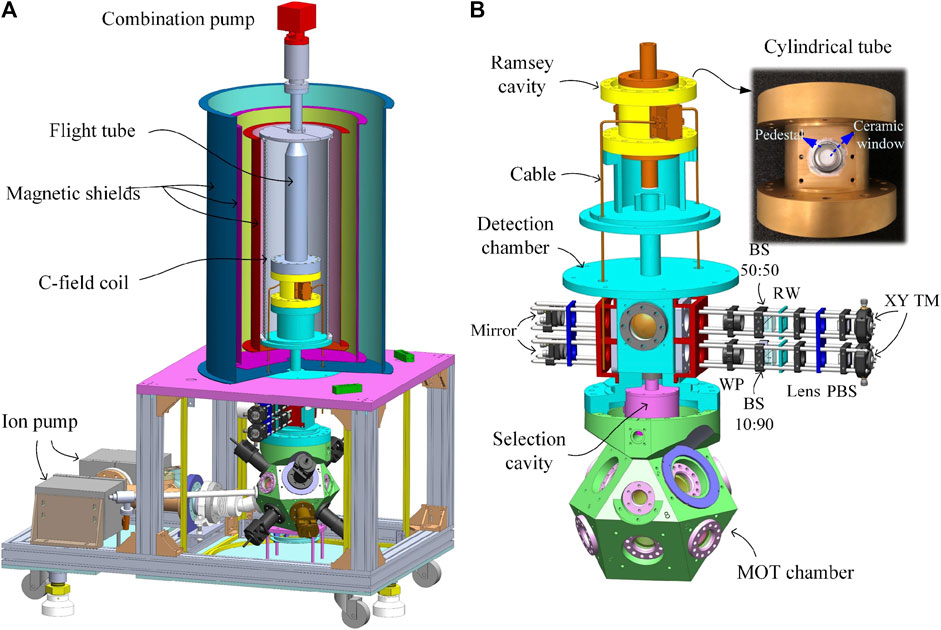
FIGURE 1. (A) Schematic of the Rb fountain clock physical package. (B) The cavities and detection system (XY TM: XY translation mount, PBS: polarization beam splitter, RW: rectangular window, BS: non-polarization beam splitter, and WP: waveplate).
Above the flight tube, a complex pump is attached to maintain a pressure of 7 × 10⁻⁸ Pa in the flight tube. Two ion pumps are attached at the lower part of the vacuum system, and each of them is shielded with soft iron to maintain a pressure of 3 × 10⁻⁷ Pa in the MOT chamber. They are placed in opposite directions to balance the magnetic field produced by them. A tube reservoir connected to the MOT chamber holds an ampule of rubidium at room temperature, providing rubidium vapor. The Rb atoms are cooled and trapped in the MOT chamber, which has a design similar to that of the NIM5 Cs fountain clock [9]. Seven beam expanding and collimating modules (BECMs) are directly mounted on the MOT chamber, providing seven laser beams (diameter 24 mm, 1/e2 level): one for repumping atoms and six for cooling atoms. The adjustments of these modules for beam collimation, polarization, and angle are performed offline. A cylindrical state-selection cavity composed of aluminum with a
The detection system of the developed Rb fountain clock has a novel design that differs from that of our Cs fountain clocks. As shown in Figure 1, to shorten the optical path and improve the reliability, the detection system, comprising two 30-mm cage systems in a parallel layout, is directly mounted on the detection chamber using a homemade adapter. The lights for atomic detection and repumping are input from two polarization-maintaining (PM) fibers and are then shaped by the cage systems to yield two rectangular parallel standing wave beams with a spacing of 50 mm in the vertical direction. A fiber is connected to the fiber adapter mounted on the XY translation mount of the upper cage system to transport the detection light, and then, the light is collimated by a lens with a focal length of 100 mm. Thereafter, a 16 × 8 mm2 rectangular detection light beam is cut out by a rectangular window (RW) and is incident on to a non-polarization beam splitter (BS) with a splitting ratio of 50T:50R. The transmission light through the BS is used as the detection light that interacts with the
Three pairs of Helmholtz coils with a mutually orthogonal layout are used to compensate for the magnetic field around the MOT chamber and the state-selection unit. A pair of anti-Helmholtz coils set along the axis of one pair of light modules is used to afford the MOT magnetic field. A vertical magnetic field of approximately 130 nT is applied in the flight tube using a double wound solenoid coil (called C-field coil) with a length of approximately 1 m surrounded by three layers of μ-metal magnetic shields, with the aim to provide a quantum axis and lift the degeneracy of the Zeeman sublevels. To obtain a uniform magnetic field, two additional coils are wound at both ends of the C-field coil.
2.2 Optical bench
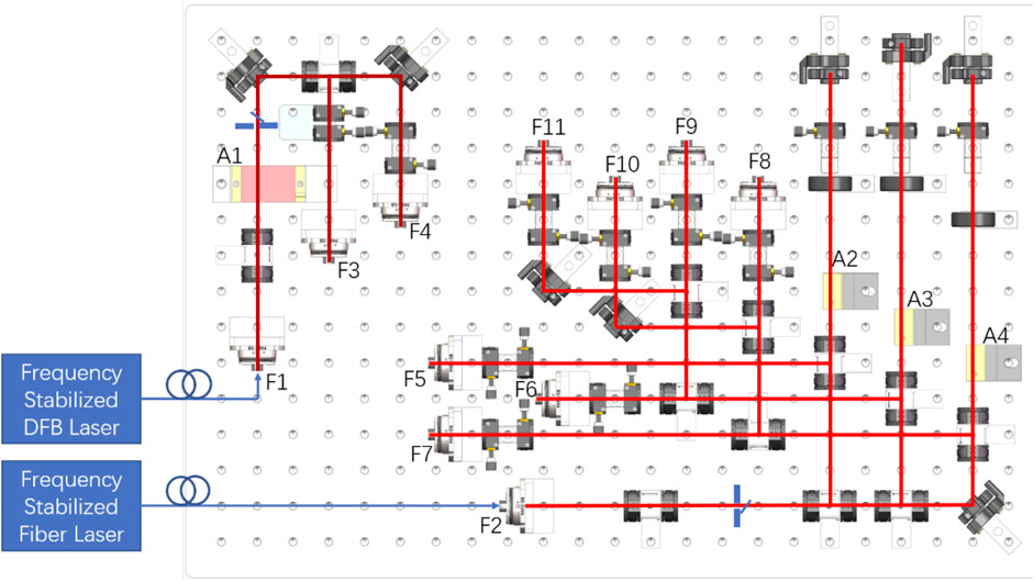
Figure 2 displays the optical schematic of the Rb fountain clock. The master laser is a commercial second harmonic generation fiber laser with an output power of more than 1 W at a wavelength of 780.24 nm. The repump laser is a customized fiber-coupled-output distributed feedback laser with an output power of more than 10 mW. The frequencies of the master and repump lasers are locked to the
The collimated repump light from F1 is frequency-shifted by A1, a +1-order single-pass AOM working at 78 MHz, and is split into two branches. Each branch is coupled into fibers via F3 and F4, forming the cooling and detection repumping light, respectively. The master laser light collimated by F2 is split into three branches: the detection light, upward and downward cooling lights. Each of them is modulated by a +1-order double-pass AOM, labeled as A2, A3, and A4, driving at 106, 98, and 98 MHz, respectively. The detection light through A2 is directly coupled into a fiber via coupler F5. The upward and downward cooling lights are both divided into three branches with equal powers and coupled into six PM fibers via couplers F6–F11. These fibers transfer the cooling light to the BECMs mounted on the MOT chamber. The cooling light power output from each BECM is greater than 50 mW. According to the diameter of the beams output from the fiber-free space modules, the cooling light density is considerably bigger than the saturation intensity (1.669 mW/cm2) for cooling and detecting Rb atoms. To minimize the noise induced by fibers, which are easily affected by ambient temperature and air pressure, a half-waveplate (WP) and a quarter-WP placed in front of the fiber are used to align the polarization direction of the input light with the slow axis of the PM fiber.
Furthermore, some special designs are incorporated in the optical bench to ensure its functionality, stability, and compactness. First, the optical path is maximally shortened using small optical elements and by optimizing their layout, and the optical height is minimized to 27 mm above the breadboard surface plane. Next, we aim to decrease the number of adjustable mounts using a spring mechanism. Since the optical path and height are preassigned according the layout of the optical elements, the adjustable range requirements of the mounts for polarization beam splitter (PBS) and AOM are small. In this optical bench, these optical elements are adjusted without any springs. Here, a synthesized module, wherein a half-WP and a PBS are mounted on two rotary adjusting frames fixed on the same pedestal, is proposed to accomplish the functions of light reflection, power splitting, and polarization rotation. The incident light at the 27 mm height level can be power-split via the PBS by rotating the half-WP. While the transmission light of the PBS maintains the same direction and height as the incident light, the deflection light can be modified to be perpendicular to the incident light while maintaining the height by properly rotating the pedestal and mount of PBS. Moreover, the commonly used multi-axis mount for AOM is simplified to an L-shape adapter with a long arm that is used to vertically fix the AOM and a short arm to fix the adapter on the breadboard. To optimize the modulation efficiency, AOM can be adjusted with two freedoms by rotating it vertically and rotating the adapter horizontally. The first-pass +1-order light of AOM will shift from the plane at the fixed optical height of 27 mm, but it will be retro-reflected since the double-pass scheme is applied. As shown in Figure 2, A2, A3, and A4 are mounted on this kind of L-shape adapter. Note that there is an exception for A1, which functions with a single-pass scheme and has to sit on a different horizontal adapter.
2.3 Microwave rack and control rack
To facilitate transportation, all instruments for microwave, vacuum, and laser involved in the fountain clock operation are integrated into two standard racks with the same sizes. The microwave rack comprises a 100 MHz distribution amplifier, two microwave sources for state selection and Ramsey interrogation, a DC power supply for the required DC voltages, three drivers of the vacuum maintenance system, and a precise current source for the C-field. The 100 MHz distribution amplifier is used to split the input signal from the H maser into multiple outputs, with minimal degradation of the input signal. A commercially available microwave source whose frequency can be changed by a computer-controlled program was employed for state selection. The interrogation microwave source is homemade, mainly comprising a 6.8 GHz DRO (dielectric resonator oscillator) and a 34 MHz DDS (direct digital synthesizer), both of which directly reference to the 100 MHz signal output from the H maser. The frequency of the 34 MHz DDS can also be precisely varied using the program. The microwave power can be turned on/off by a TTL (transistor-transistor logic) control microwave switch, which is located between two DC blocks interlinked by the feeding cables. The DC blocks are used to isolate the ground connection while avoiding unexpected perturbation. The control rack includes a display screen, a computer with commercial multifunctional IO cards, an I/O interface chassis, a multichannel signal generator for the AOM driver system, and two laser control systems. Using the control program coded by LabVIEW, the computer with the commercial multifunctional I/O cards can generate digital and analog time sequences, acquire the analog signal from the fluorescent detector at the detection zone, and realize the close-loop control of the frequency of the interrogation microwave source. Since the optical system has been compacted into a small-sized optical breadboard, it can be placed at the bottom of the control rack, but it is currently placed on a single support frame.
2.4 Operation time sequence
In addition to the new hardware designs, some new processes are adopted in the operation time sequence. To improve the short-term instability of the fountain clock, the duration of the operation time sequence is set to 1.2 s, which is similar to that of our cesium fountain clocks. This facilitates the comparison between them. The MOT loading time is 340 ms, and the cold atoms are accelerated upward in steps of 1 ms by modifying the frequency of the cooling beams. Thereafter, the power and frequency of the cooling beams are strictly synchronously changed in steps of 1.2 ms for the polarization gradient cooling. Then the cold atoms exhibit a ballistic trajectory, wherein the atoms experience in series Rabi interactions in the selection cavity, pushing the
3 Instability deterioration related to ramsey cavity and atomic number
The fractional frequency instability of a fountain clock is well known to be [27, 28].
where τ is the averaging time, Tc is the duration of one fountain cycle, Qat = ν0/Δν is the quality factor of the atomic clock transition, ν0is the central frequency of the clock transition, Δν isthe line width of the center Ramsey fringe, and SNR is the signal-to-noise ratio. In the parentheses, the first term denotes the limitation of the quantum projection noise andNat is the total number of detected atom; the second term denotes the photon scattering noise, nph is the average scattering photons for each atom, andεc is the coefficient of fluorescent collection; the third term represents the contribution of the detection system and σδN is the noise for detection; and the last term represents the phase noise of the local oscillator. Clearly, to achieve lower instability, the interrogation time could be increased, the atom collecting time could be reduced, or the SNR could be improved.
During the operation of fountain clocks, the change of the ambient temperature induces a shift of the cavity resonance frequency from its original design. Thus, the microwave power building inside the cavity will accordingly change, consequently changing the transition probability. In other words, the SNR gets worse, and consequently, the clock instability becomes worse. From Eq. 1, the instability of a clock can be expressed as the fluctuations of the Ramsey transition probability δP as follows [29]:
where δP is the probability fluctuations at the fountain clock operation frequency ν0±Δν/2. It can be expressed as
where b is proportional to the square root of the microwave power. δ denotes the relative change of bτin with the cavity temperature and it can be expressed as δ = 1 − (pΔT/p0)1/2
where Tp is the time constant when the power changes by (p0 − pΔT)/e because it is a slowly time-varying process; we assume its value to be ∼10,000 s in the real case.
A new double-metal cavity (Ti&OFC cavity) with a Ti tube and two OFC caps is fabricated to reduce the clock’s temperature sensitivity, and the measured temperature sensitivity is −16.3 Hz/°C [26]. Assuming that both the resonance frequencies of the OFC cavity and the Ti&OFC cavity match the Rb clock frequency within 50 kHz, the microwave power inside the cavity will be within 10% from the optimal interrogation power, Tc = 1.2 s, and Δν = 1.2 Hz. The instability deterioration due to the interrogating microwave power variations are evaluated from Eq. 4 and are shown in Figure 3.
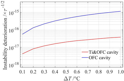
FIGURE 3. Calculated clock instability deterioration due to the temperature variations for two different types of Ramsey cavities. The red line is the instability of an OFC cavity, and the blue dashed line is the instability of a Ti&OFC cavity.
Figure 3 shows that when the temperature increases by 1.0°C within 10,000 s, the corresponding instability deterioration is
4 Experimental results
4.1 Measurement of sensitivity of optical system to the temperature fluctuations
To measure the sensitivity of the optical system to temperature fluctuations, the entire optical bench was heated to different temperatures, and the output power of light from the fiber was monitored at the same time. The longest optical path with a length of 1.275 m was chosen, which should be the most sensitive to temperature variations. The entire optical bench was enclosed in a layer of foam and the air inside was heated using a resistance heater. The duration of the measurement was about 220 min. The results are shown in Figure 4.
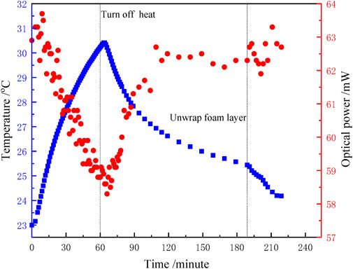
FIGURE 4. Variations of temperatures and output light powers vs time. At 60 min, the heat was turned off. The blue squares indicate the measured bench temperatures, and the red dots indicate the measured light output from the fiber.
In Figure 4, the blue squares represent the measured temperature of the optical bench, and the red dots represent the measure light output from the fiber. The optical bench was heated for 1 h, and the temperature increased from 23 to 30.4°C. Then, the heat was turned off, and the system was cooled. Since the time constant is too long for the system to cool to room temperature, the foam layer was unwrapped at 189 min. As shown in Figure 4, the peak-to-peak variation of the light output power during the entire temperature variation was less than 5.8 mW, about 10% of the output power. When the system was cooled down, the power recovered within acceptable level. This suggests that the proposed compact optical system is robust and insensitive to temperature variations within 7°C.
Figure 5 displays the typical atomic fluorescent signals in 1 day for the fountain clock working in the PID locking mode. The standard deviation was 3.07 with a mean value of 461.35 in arbitrary units, and the peak-to-peak atom number fluctuation in 1 day was 4.3%.
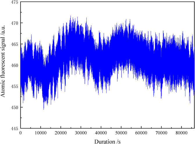
FIGURE 5. Atomic fluorescent signal in 1 day (Vertical axis is the sum of the atomic fluorescent signal of
Considering that the cavity-pulling frequency shift is proportional to the number of atoms interacting with the microwave in the cavity [30, 31],
Here,
4.2 Frequency shift evaluations
Although Type B uncertainty evaluations are not necessary for a time-keeping clock, they will help eliminate the unexpected frequency shifts as the residual fluctuations of a large frequency shift deteriorate the frequency instability. The light shift and the microwave-power-related frequency shift could be a problem and were thus examined in the developed Rb fountain clock.
Various methods are used to eliminate stray light and reduce the possible light shift, such as covering up all fiber couplers and optical shutters with black aluminum foils and increasing the frequency detuning of AOMs during the interrogation. To verify that no light shift occurs, the Rb fountain clock was alternatively operated in two sequences with different AOM-driven powers for the cooling/detection beams during the interrogation, and the results show that the fractional frequency difference is less than 1 × 10–15. The microwave-power-related frequency shifts were also analyzed by operating the fountain at different interrogation microwave powers. The fractional frequency difference between microwave powers of P0 and 9P0 was 2 × 10–15. All the evaluation results show that regular main frequency shifts, such as the light shift and microwave-power-related shift, are small enough to ensure good instability.
4.3 Long-term instability
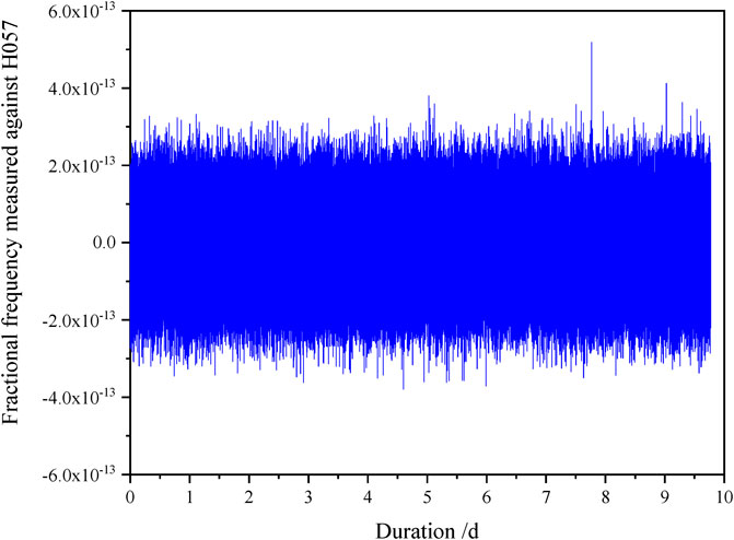
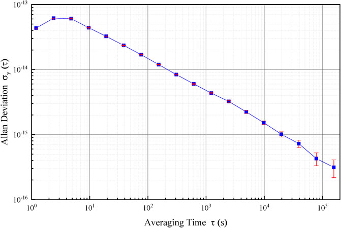
The Rb fountain clock with the 100 MHz signal from the H-maser H057 was continuously operated for 10 days from MJD 59693 to MJD 59703. The results are shown in Figure 6. The clock instability was 1.49 × 10⁻¹⁴ and 4.1 × 10⁻¹⁶ for the averaging time of 100 s and 1 day, respectively, as shown in Figure 7.
The cycle time of one fountain sequence is 1.2 s, and the frequency can be locked after two fountain cycles. Thus, the shape of the instability figure in the short time range depends on the parameters of proportional-integral (PI) control. The PI setting used in the Rb fountain clock is small, and the actually servo frequency is small. This makes the stability at the smallest averaging time less than that of the third averaging time, where the frequency is already in steady-state locking.
5 Conclusion
NIM has been devoted to the research of Cs fountain clocks for decades and has developed two fountain clocks NIM5 and NIM6, achieving Type B frequency uncertainties of 9 × 10–16 and 5.8 × 10⁻¹⁶, respectively. Herein, a novel Rb fountain clock has been built for time keeping by adopting some important features of Cs fountain clocks and some new improvements. One of the most important features of the developed clock is a double-metal Ramsey cavity, which has been used for the first time, to our knowledge, to reduce the clock temperature sensitivity. This cavity functions as both a microwave resonator and a part of the vacuum chamber; consequently, the clock physical package is smaller and lighter, has less microwave leakage to the interrogation regime, and is much easier to assemble. Additionally, the resonance frequency of the cavity can be fine-tuned after vacuum baking. A new compact optical system was also designed and built to ensure stable light power outputs. The temperature dependency of the cavity and optical system were studied. The results show that the Rb fountain clock robustly operates in a large ambient temperature range. During 10 days operation, an instability of
Data availability statement
The original contributions presented in this study are included in the article/Supplementary Material. Further inquiries can be directed to the corresponding author.
Author contributions
CW contributed to the design of the optical system, implementation the experiments, data collection, and interpretation of the results and manuscript preparation. FF was responsible for the physical system and experiment implementation. LK contributed to the magnetic shield, control system, and experiments as well as reviewed the editing. ZF contributed to microwave cavity and physic system design and reviewed the editing. DS contributed to the fluorescent collection system, C-field DC current supply, and reference frequency distribution. ZY helped with the experiment and reviewed the editing. LT supervised the project and contributed to funding acquisition.
Funding
This research was supported by project of the National Natural Science Foundation of China (11873044).
Acknowledgments
We sincerely thank Professor Wang Yuqiu. He is the pioneer in the fountain clock research in China, and as our mentor, he had numerous discussions with us and gave us many valuable suggestions to help us improve our fountain clock. Especially, he has been helped evaluate the cavity pulling and Majorana transition in our NIM5 and NIM6 uncertainty evaluation. We also thank the time keeping lab for their cooperation.
Conflict of interest
The authors declare that the research was conducted in the absence of any commercial or financial relationships that could be construed as a potential conflict of interest.
Publisher’s note
All claims expressed in this article are solely those of the authors and do not necessarily represent those of their affiliated organizations, or those of the publisher, the editors and the reviewers. Any product that may be evaluated in this article, or claim that may be made by its manufacturer, is not guaranteed or endorsed by the publisher.
References
1. Ramsey NF. The past, present, and future of atomic time and frequency. Proc IEEE (1991) 79(7):921–6. doi:10.1109/5.84968
2. Clairon A, Salomon C, Guellati S, Phillips WD. Ramsey resonance in a Zacharias fountain. Europhys Lett (1991) 16(2):165–70. doi:10.1209/0295-5075/16/2/008
3. Clairon A, Laurent P, Santarelli G, Ghezali S, Lea S, Bahoura M. A cesium fountain frequency standard: Preliminary results. IEEE Trans Instrum Meas (1995) 44(2):128–31. doi:10.1109/19.377790
4. Gerginov V, Nemitz N, Weyers S, Schroder R, Griebsch D, Wynands R. Uncertainty evaluation of the caesium fountain clock PTB-CSF2. Metrologia (2010) 47:65–79. doi:10.1088/0026-1394/47/1/008
5. Guéna J, Abgrall M, Rovera D, Laurent P, Chupin B, Lours M, et al. Progress in atomic fountains at LNE-SYRTE. 2012 IEEE Trans Ultrason Ferroelectr Freq Control (2012) 59:391–409. doi:10.1109/tuffc.2012.2208
6. Domnin S, Baryshev N, Boyko I, Elkin GA, Novoselov AV, Kopylov LN, et al. The MTsR-F2 fountain-type cesium frequency standard. Meas Tech (2013) 55:1155–62. doi:10.1007/s11018-012-0102-0
7. Heavner P, Donley A, Levi F, Costanzo G, Parker TE, Shirley JH, et al. First accuracy evaluation of NIST-F2. Metrologia (2014) 51:174–82. doi:10.1088/0026-1394/51/3/174
8. Levi F, Calonico D, Calosso E, Godone A, Micalizio S, Costanzo GA. Accuracy evaluation of ITCsF2: A nitrogen cooled caesium fountain. Metrologia (2014) 51:270–84. doi:10.1088/0026-1394/51/3/270
9. Fang F, Li M, Lin P, Chen W, Liu N, Lin Y, et al. NIM5 Cs fountain clock and its evaluation. Metrologia (2015) 52:454–68. doi:10.1088/0026-1394/52/4/454
10. Weyers S, Gerginov V, Kazda M. Advances in the accuracy, stability, and reliability of the PTB primary fountain clocks. Metrologia (2018) 55:789–805.
11. Takamizawa A, Yanagimachi S, Hagimoto K. First uncertainty evaluation of the cesium fountain primary frequency standard NMIJ-F2. Metrologia (2022) 59:035004. doi:10.1088/1681-7575/ac5e7b/meta
12. Beattie S, Jian B, Alcock J. First accuracy evaluation of the NRC-FCs2 primary frequency standard. Metrologia (2020) 57:035010. doi:10.1088/1681-7575/ab7c54
13. Devengoes L, Domenico G, Stefanov A. Measurement of the magnetic field profile in the atomic fountain clock FOCS-2 using Zeeman spectroscopy. Metrologia (2017) 54:239–46. doi:10.1088/1681-7575/aa62d1
14. Acharya A, Yadav S, Arora P. Present status of primary frequency standards at NPL, India. In: 2016 IEEE International Frequency Control Symposium (IFCS); 09-12 May 2016; New Orleans, LA, USA (2016). p. 1–2. doi:10.1109/FCS.2016.7546774
15. Fang F, Chen W. Advances in the NIM Cs fountain clocks. In: 2019 Joint Conference of the IEEE International Frequency Control Symposium and European Frequency and Time Forum; 14-18 April 2019; Orlando, FL, USA, 8856067. EFTF/IFC (2019).
16. Fang F, Chen W, Liu K The preliminary evaluation of the new fountain clock NIM6. 2019 URSI Asia-pacific Radio Science Conference (2019) 8738417:1–2.
17. Guéna J, Abgrall M, Clairon A, Bize S. Contributing to TAI with a secondary representation of the SI second. Metrologia (2014) 51(1):108–20. doi:10.1088/0026-1394/51/1/108
18. Lin Y, Wang Q, Fang Z, Cao S, Li Y. A 87 Sr optical lattice clock with 2.9×10 -17 uncertainty and its absolute frequency measurement. Metrologia (2021) 58(3):035010. doi:10.1088/1681-7575/abf33e
19. Tiesinga E, Verhaar J, Stoof C, van Bragt D. Spin-exchange frequency shift in a cesium atomic fountain. Phys Rev A (Coll Park) (1992) 45:2671–3. doi:10.1103/physreva.45.r2671
20. Gibble K, Chu S. Laser-cooled Cs frequency standard and a measurement of the frequency shift due to ultracold collisions. Phys Rev Lett (1993) 70:1771–4. doi:10.1103/physrevlett.70.1771
21. Fertig C, Gibble K. Measurement and cancellation of the cold collision frequency shift in an87RbFountain clock. Phys Rev Lett (2000) 85(8):1622–5. doi:10.1103/physrevlett.85.1622
22. Fertig C, Bouttier J, Gibble K. Laser-cooled 87Rb clock, conference on precision electromagnetic measurements. Conf Dig CPEM (2000) 2000:7. doi:10.1109/CPEM.2000.850848
23. Cheng H, Zhang Z, Deng S, Ji J, Ren W, Xiang J, et al. Design and operation of a transportable 87Rb atomic fountain clock. Rev Sci Instrum (2021) 92:054702. doi:10.1063/5.0047715
24. Peil S, Crane S, Swanson T. The USNO rubidium fountain. IEEE International Frequency Control Symposium and Exposition (2006). p. 304–6. doi:10.1109/FREQ.2006.275402
25. Blinov I, Boiko A, Kosheliaevskii N, et al. First experiments on application of Rb fountain frequency standards for TA(SU) time scale maintenance. In: 2018 European Frequency and Time Forum; 10-12 April 2018; Turin, Italy. EFTF (2008). p. 257–62. doi:10.1109/EFTF.2018.8409045
26. Zheng F, Fang F, Wang X, Chen W, Liu K, Dai S, et al. A low temperature-sensitive Ramsey cavity for Rb fountain clocks. In: China satellite navigation conference (CSNC 2022) proceedings. Singapore: Springer (2022). p. 393–402. doi:10.1007/978-981-19-2576-4_35
27. Wynands R, Weyers S. Atomic fountain clocks. Metrologia (2005) 42(3):S64–79. doi:10.1088/0026-1394/42/3/s08
28. Szymaniec K, Park E, Marra G, Chalupczak W. First accuracy evaluation of the NPL-CsF2 primary frequency standard. Metrologia (2010) 47(4):363–76. doi:10.1088/0026-1394/47/4/003
29. Santarelli G, Laurent P, Lemonde P, Clairon A, Mann AG, Chang S, et al. Quantum projection noise in an atomic fountain: A high stability cesium frequency standard. Phys Rev Lett (1999) 82:4619–22. doi:10.1103/physrevlett.82.4619
30. Bize S, Sortais Y, Mandache C, Clairon A, Salomon C. Cavity frequency pulling in cold atom fountains. 2001 IEEE Trans Instrum Meas (2001) 50:503–6. doi:10.1109/19.918177
Keywords: fountain clock, time keeping, Rb, double metal cavity, instability
Citation: Weiliang C, Fang F, Kun L, Fasong Z, Shaoyang D, Yani Z and Tianchu L (2022) Development of Rb fountain clock for time keeping. Front. Phys. 10:956452. doi: 10.3389/fphy.2022.956452
Received: 30 May 2022; Accepted: 03 August 2022;
Published: 15 September 2022.
Edited by:
Emmanouil P. Benis, University of Ioannina, GreeceReviewed by:
Tom Parker, National Institute of Standards and Technology (NIST), United StatesPoonam Arora, NPLI, India
Copyright © 2022 Weiliang, Fang, Kun, Fasong, Shaoyang, Yani and Tianchu. This is an open-access article distributed under the terms of the Creative Commons Attribution License (CC BY). The use, distribution or reproduction in other forums is permitted, provided the original author(s) and the copyright owner(s) are credited and that the original publication in this journal is cited, in accordance with accepted academic practice. No use, distribution or reproduction is permitted which does not comply with these terms.
*Correspondence: Chen Weiliang, Y2hlbndsQG5pbS5hYy5jbg==; Fang Fang, ZmFuZ2ZAbmltLmFjLmNu
 Chen Weiliang
 Fang Fang
 Liu Kun