 Ivana Kovacic
 Zvonko Rakaric2
 Zeljko Kanovic
 Vladimir Rajs
95% of researchers rate our articles as excellent or good
Learn more about the work of our research integrity team to safeguard the quality of each article we publish.
Find out more
ORIGINAL RESEARCH article
Front. Phys. , 31 August 2022
Sec. Physical Acoustics and Ultrasonics
Volume 10 - 2022 | https://doi.org/10.3389/fphy.2022.934998
This article is part of the Research Topic New Trends in Architectured Functional Materials View all 6 articles
This research focuses on the analysis of the model and performance of lightweight metastructures encompassing a distributed array of internal homogenous oscillators, integrated into the host structure to create a single-piece element. This metastructure performs longitudinal vibrations, whose axis is colinear with the direction of the transverse vibration of the internal oscillators. First, the mechanical models of the separate elements of the metastructure and the metastructure as a whole are created and considered. The first modal frequencies of longitudinal vibrations of the metastructure with blocked and free internal oscillators are tuned to the first modal frequency of transverse vibration of one internal oscillator, yielding the optimal number of internal oscillators for this to be achieved, which is a new result for the proposed design. This theoretical result is then checked experimentally with the metastructures produced by 3D printing technology, comprising a different number of internal oscillators, all of which have the same natural frequency. Besides validating the theoretical results, experimental investigations with blocked and freely vibrating internal oscillators of the constant natural frequency are used to explore other performance characteristics, such as the width of the regions where the reduced amplitude is achieved. Finally, based on the theoretical and additional numerical results, the internal oscillators are modified in two ways, which is an original approach: their natural frequency is increased linearly and nonlinearly along the metastructure in accordance with the previous new theoretical results. The benefits of such new redesigns for the multi-modal performance characteristics of the metastructure are discussed.
Low-frequency noise and vibrations occurring in nature and industry can adversely affect the environmental and occupational conditions, including human health and working regimes of various engineering systems. One of the recent solutions for their mitigation involves the design of metastructures, developed from a metamaterial-inspired concept. Metamaterials encompass the integration of additional elements into the basic constituent(s) to achieve a certain desired feature fundamentally different from the one that the constitutive elements have and from those already existing in nature. Analogously, metastructures involve the integration of internal oscillators (also referred to in the literature as resonators, absorbers, or tuned-mass dampers) into the basic structure to achieve its desirable dynamic behavior, such as vibration mitigation in a certain frequency region or along a wider frequency band.
The metastructures developed so far can be distinguished as containing internal, external, or attached oscillatory elements [1], utilizing mass-in-mass or mass-on-mass principles. Of interest for this work is the case of mass-in-mass systems. Such systems can have only one or multiple internal oscillators. The case with only one internal oscillator has been considered when the internal mass is movable [2, 3] or fixed [4]. The case of multiple internal oscillators has been investigated, with them being arranged in parallel [5] or in series inside one mass [6, 7].
Additionally, they can be divided into two groups with respect to the material of these masses, which is of interest for this work. The pioneering studies [8, 9] investigated the locally resonant systems made of lead spheres coated with rubber, being the first to discover the low-frequency bandgap. Yu et al. [10] confirmed the existence of low-frequency bandgaps using an aluminum beam with periodically attached rubber and copper rings as vibration absorbers. In order to demonstrate an engineering application of an aluminum metastructural plat in a low-frequency bandgap range, the anisotropic inclusions with the material properties of lead, epoxy, and rubber were proposed [11]. The metastructure composed of tungsten columns and rubber placed in a chiral lattice, yielding a very low-frequency bandgap, was presented in [12]. However, such additions to metastructures carry considerable weight, which limits their potential engineering applications in lightweight structures. The intensive development of advanced manufacturing technologies, such as 3D printing, has provided the possibility to create complex structures in a relatively easy way, including lightweight metastructures. The transverse vibrations of a metastructural beam whose sheets are laminates and core is foam with built-in resonators were investigated in [13]. It was shown therein that, by tailoring the local resonance frequency of the resonator, the range and the location of the bandgap can be selected. Longitudinal vibrations of a metastructural rod with periodic absorbers made of 3D polymer printing were studied in [14], with the tunability realized at a locally resonant frequency. A metastructural panel made of built-in resonators and sandwich panels was proposed to block out-of-plane vibration in [15]. Two different boundary conditions were tested: cantilevered and free–free, confirming that the metamaterial core reduces the peak dynamic response at the natural frequencies of the sandwich panel. In [16], single-piece elastic metamaterial beams and plates with interconnected resonators were proposed. Therein, the resonators create a chain so that their interaction leads to a large bandgap at the transverse vibration frequency of the independent resonators and a small bandgap at higher frequencies. The authors observed that more unit cells are needed to produce a significant transmission reduction. A metastructure composed of evenly spaced non-symmetric resonators attached to a beam with a Π-shaped cross-section was investigated in [17] to detect the influence of the change in periodicity caused by additive manufacturing variability. It was shown therein that the mistuned resonators could change the vibration attenuation performance of the metastructure when even small levels of variability exist. The system under consideration in [18] consisted of beams with evenly attached resonators, and the effects of the variability introduced by 3D printer manufacturing (Selective Laser Sintering) on locally resonant metastructures produced were examined. The authors combined a correlation technique for frequency response measurements and a Bayesian framework to estimate the design parameters (the mass ratio and the resonators’ natural frequency) for vibration attenuation. The approach used in [19] is based on liquid-solid interaction: instead of using cohesive material, the authors proposed using the internal liquid as scattering core and thin layers as coatings, enabling easy modification of the system and its capability to block vibration in the broad low-frequency range. The hierarchical metastructures with bi-walled beams were fabricated and assembled using a 3D printing technique in [20]. Experiments were conducted, and the results were validated with the analytical and numerical models with a satisfactory agreement. The tunability and recoverability of the architected metastructures under tension and compression were explored, pointing out future possibilities to utilize structurally unstable elements. In [21], an hourglass-shaped lattice metastructure consisting of two oppositely oriented coaxial domes was presented. Such an approach yields higher customizability and tailorability of its dynamic response. Six classes of hourglass-shaped lattice metastructures were developed by combining solid shells, honeycomb lattices, and auxetic lattices to achieve tunable metastructures over a wide range of operating frequencies. Inman et al. proposed a concept in which the absorbers and the base are made of the same material [22–24], forming a continuous one-piece metastructure, improving it gradually from the first form applicable to longitudinal vibrations [22] to the version that is suitable for longitudinal, transverse, and torsional vibrations [24].
Our paper analyzes the originally proposed concept [22] in detail in terms of the corresponding mechanical models, tuning between the first modal frequencies of the internal oscillators and the metastructure as a whole. The primary focus is on the fundamental natural frequency of the structure given the interest of plenty of engineering applications to suppress the response near the fundamental mode of vibration as it typically results in the highest magnitude response. This study, in its first part, compares the effectiveness of a structure with no absorbers (i.e., the case when the in-built resonators are blocked) with the one with multiple active absorbers. Theoretical, experimental, and numerical investigations are included subsequently. Theoretical considerations are carried out to define certain guidelines for modeling as presented in Section 2, whereas the optimal number of the internal oscillatory elements needed to achieve the frequency tuning is given in Section 3, which have not been provided for this concept so far. Our experimental validation of this optimal number is presented in Section 4, also yielding additional insight into the characteristic dynamic behavior of the metastructures with respect to their vibration mitigation performance. Based on the theoretical results from Section 2 and some additional insight gained numerically in COMSOL Multiphysics, two types of newly redesigned metastructures are created in the second part of the study, Section 5, to improve their multi-modal behavior. The redesign is done in two approaches: first, the natural frequency of the internal oscillators is changed linearly along the metastructure and then nonlinearly. It should be pointed out that this change is not done arbitrarily but in accordance with the preceding theoretical results, which is an original approach.
A metastructure under consideration has a repetitive structure, and its shape is defined in [22], which is plotted here in the upper part of Figure 1. The panel with “A-A” in this figure corresponds to a cross-section view of the structure. For the sake of the subsequent consideration, the metastructure is examined here as combining three systems (Systems 1–3), as labeled in Figure 1.
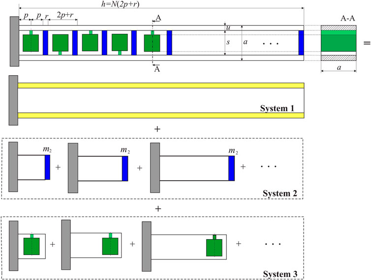
FIGURE 1. Metastructure under consideration in different configurations: System 1 (fixed-free rod), System 2 (additional parts with transversal masses connected in series), and System 3 (parts with internal oscillators).
Its basic structural unit has a hollow square cross-section, labeled as System 1 in Figure 1. The transversal elements (plates) shown in Figure 1, labeled as System 2, divide the structure into parallelepipedal units. One internal oscillator is placed in each unit, and it has the shape of a clamped beam with a concentrated mass on the top (labeled as System 3 in Figure 1). The width of the walls of the basic structure is labeled by u and the distance between them by s; the width of the transversal elements is labeled by r. There are N identical internal oscillators, which are integrated into the walls of the basic structure, composing a one-piece metastructure. The width of each unit is defined as 2p, so that the location where the oscillators are attached to the wall is defined by the distance p from the transversal elements. A series of these distributed internal oscillators, which play an essential role in the vibration mitigation of the whole metastructure, perform transverse (bending) oscillations in the direction that is collinear with the direction of longitudinal (axial) oscillations of the metastructure. The following sections of this paper contain the considerations of the mechanical models of the metastructure and the internal oscillators, as well as the determinations of their fundamental frequencies of interest for this study. Although separate analytical considerations are classical in the mechanical sense, the authors believe that their combinations have not been exploited in this way before.
Let us consider first System 1 from Figure 1, treating it as a fixed-free hollow bar of length h = N (2p + r) that performs longitudinal vibrations (System 1 will be abbreviated as S1 in the subsequent text and equations). Knowing its modulus of elasticity E and the mass density ρ, its fundamental frequency of longitudinal vibrations is known as follows [25]:
In expression (1), the correction in relation to the ideal isotropic rod of the infinitely small cross section is included, where ν is Poisson’s ratio, while
Let us now consider System 2 (it will be abbreviated as S2 in the subsequent text and equations), considering transversal elements of mass m2 (they are shown in blue in Figure 1). The corresponding units are attached mutually in series so that their corresponding fundamental frequency can be obtained as follows:
The internal oscillators perform transverse vibration. Each internal oscillator consists of two parts (Figure 2A): P1 denotes the parallelepipedal part of mass M, which is treated as a concentrated mass; P1 is attached to Part P2 of mass m, which is considered as a column of length L (Figure 2B). Their 3D model with all characteristic dimensions a, b, d, and e is shown in Figure 2A.
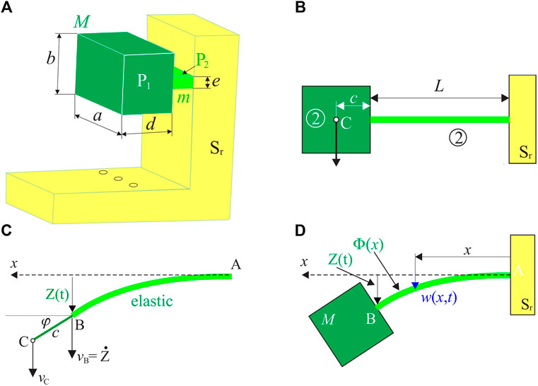
FIGURE 2. Internal oscillator: (A) 3D model; (B) presentation as a clamped beam with a concentrated mass on the top; (C) kinematics of the concentrated mass; (D) deformed configuration.
The corresponding first modal frequency will be determined by applying the theory of generalized coordinates [26]. The first mode is considered only, and the variables x and t are separated as follows
Part P2 exhibits plane motion, and its kinetic energy contains the translatory and rotational parts. The former depends on the velocity
where its mass M is defined by M = ρ a b d, whereas the cross section is given by A = a2
The velocity of Point C can be determined via the velocity of Point B with the assumption that the angle
The following dimensionless parameters are introduced now:
where T is the fundamental period of this oscillator.
The normalized kinetic energy of Part P1 can be represented as
where
and the volume of Part P1 is
The kinetic energy of Part P2, which is considered as a system with distributed mass and stiffness, can be obtained as follows:
where the mass per unit and length of Part P2 are, respectively, given by
The normalized kinetic energy
The potential energy of the internal oscillator resonator stems from the flexural strain energy of Part P2. By using
where I denotes the moment of inertia I = ae3/12, while
Similarly, the normalized potential energy of the resonator reads as
Based on Eqs. 3,8,10, the fundamental frequency of the internal oscillators can be represented as
By using Eqs. (5, A1–A5) from Appendix, as well as the dimensions from Figure 2A, this first modal frequency is found to be
where
The metastructure is created by attaching internal oscillators to the transverse elements of the baseline structure (System 3 in Figure 1). When blocked, they can be treated the same way as the transversal elements of System 2. By using their dimensions and volume defined in Section 2.2, the corresponding frequency is found to be
Thus, the frequency of the metastructure with blocked internal oscillators is defined by
To treat the case when the internal oscillators are free to oscillate, Dunkerley’s method [27, 28] is utilized. Based on the geometry shown in Figure 2, the position of the i-th resonator is defined by (2i + 1) p + i r, as shown in Figure 3. The equivalent model of series-connected springs is created (Figure 3, right part), and the following expression for the fundamental frequency is derived:
where M is the mass of each of them, κi and kr are the stiffness constants from the equivalent model (Figure 3, right part), A is its cross-section, and ωr is defined by Eq. 13.
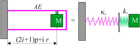
FIGURE 3. Mechanical models of the internal oscillator in a metastructure.
The frequency of the metastructure with free internal oscillators is given by
The tuning condition is defined in a way that the first modal frequency of transverse vibrations of internal oscillators should be equal to the first modal frequency of longitudinal vibrations of the metastructure, which means that Eqs. 13,16 are used to derive
This ratio is plotted in terms of the number of internal oscillators N in Figure 4, while other parameters are taken from Table 1, as defined in [22]. In addition, Poisson’s ratio ν needed for Eq. 1 is 0.3. It should be noted that this ratio does not depend on the ratio (E/ρ)1/2. For the ratio defined by Eq. 19 to be equal to unity and satisfy the tuning condition, the theoretical analysis shows that N needs to be equal to 8, as labeled in Figure 4.
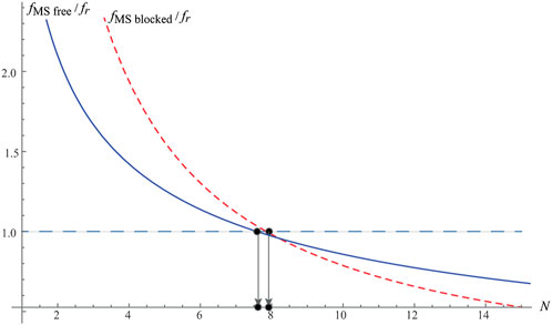
FIGURE 4. Ratio
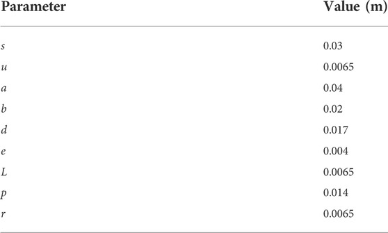
TABLE 1. System parameters.
Analogously, based on Eqs. 13,18, the ratio of the frequency of the metastructure with free internal oscillators normalized with the frequency of internal oscillators is derived:
This ratio is plotted in Figure 4, too. It is interesting to note that it becomes equal to unity when N is close to 8, but the exact value is slightly less than the one obtained for blocked absorbers. However, the obtained results are very close to each other. This analytical result for the metastructure under investigation is novel, and, as far as the authors are aware, it has not been known as such so far. It should also be noted that the region on the righthand side of the first dot labeled in Figure 4 corresponds to
One internal oscillator and different versions of the metastructure were made by 3D printing (fused filament fabrication) with a resolution of 0.1–0.3 mm and 100% filling of acrylonitrile butadiene styrene (ABS) with E = 1490 MN/m2 and ρ = 1.05 g/cm3 (these two values have been obtained from the manufacturer as the material characteristics). The internal oscillator is printed with support added for the sake of experimental analysis, whereas the metastructures are printed with 6, 8, and 10 internal oscillators (Figure 5).
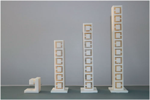
FIGURE 5. 3D printed specimens (from left to right) with the support added for the sake of experimental analysis): one internal oscillator and the metastructures with 6, 8, and 10 internal oscillators.
To examine the transverse oscillations of the internal oscillator and the longitudinal oscillations of the metastructures, they are exposed to the excitation of the base in the vertical direction. The excitation was created, and the response of the top of the metastructure was recorded by the vibration test system (Figure 6), which includes one LDS vibrator type V408,10/32UNF; one LDS amplifier type LPA100; two accelerometers type 4534-B; one COMMETUSB controller type COM-200, and software package SCO-107 for “Sine, Random & Shock” excitation (the first type of excitation was applied with the magnitude equal to unity).
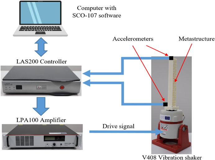
FIGURE 6. Experimental setup.
First, one internal oscillator is experimentally tested (Figure 7). The accelerometer is placed on the top, yielding the amplitude-frequency characteristic for the non-dimensional amplitude shown in Figure 7 (the non-dimensional amplitude is obtained by dividing the vibration amplitude by the length L of the clamped beam, i.e., Part 2, Figure 2B). It is seen that the first modal frequency of its transverse oscillations is 588 Hz. It is of interest now to compare this value with the one obtained theoretically. For the values of E and ρ given by the manufacturer given above, based on Eqs. 13,14, we get that the first modal frequency is 650 Hz. This difference with respect to the experimental value can be explained by the fact that the values for E given by the manufacturer differ from the values for the modulus of elasticity of a structure due to its exposure to the technological process and the dynamic loading. On the contrary, the experimentally obtained value for the modal frequency can be used for a more precise estimate of the modulus of elasticity for a predetermined value of density. Thus, using Eqs. 13,14 for the frequency of 588 Hz and ρ = 1.05 g/cm3, we get that E = 1170 MN/m2. This value can be treated as the corrected value of the modulus of elasticity obtained based on analytical and experimental approaches.
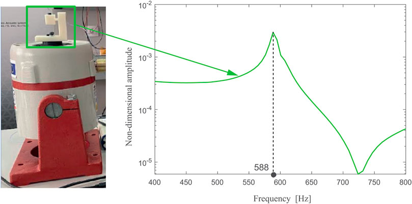
FIGURE 7. Experimentally obtained amplitude-frequency characteristics of one internal oscillator.
Then, the metastructure with 6, 8, and 10 internal oscillators is tested in two configurations (Figures 8–10), with blocked absorbers and free (active) internal oscillators. Note that all of them are equal, that is, with the same natural frequency. Blocking was achieved by inserting thin and light pieces of foam between them and the horizontal surfaces of the structure above and below the concentrated masses, as seen in the left parts of Figures 8–10. By placing the accelerometer again on top of both configurations, the corresponding amplitude-frequency characteristics for their normalized amplitude are obtained, as shown in Figures 8–10. In this case, the non-dimensional amplitude is obtained by dividing the vibration amplitude by the overall height of the metastructure.
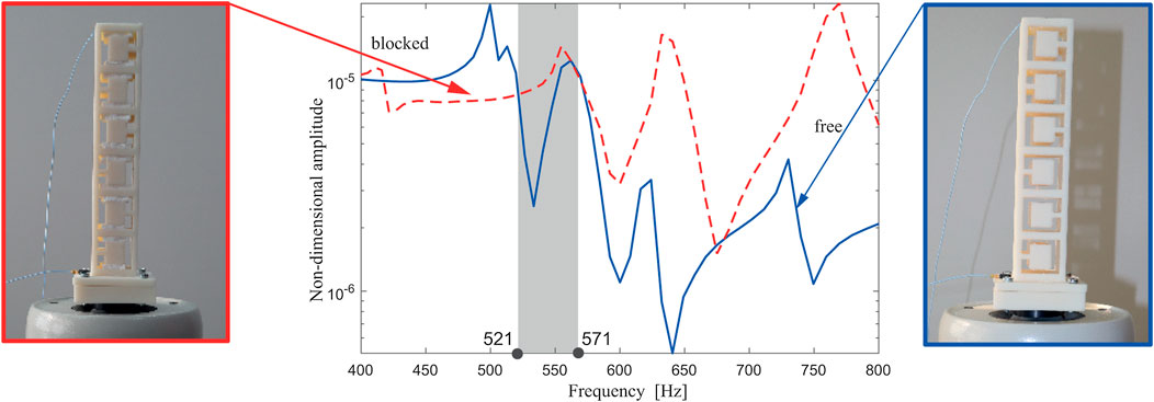
FIGURE 8. Experimentally obtained amplitude-frequency response curve of the metastructure with internal blocked (red dashed line) and free (blue solid line) internal oscillators.
In all three cases (Figures 8–10), the response with blocked and free resonators is plotted and compared mutually. The shaded region corresponds to the attenuation region where the reduction of the non-dimensional amplitude around the first modal frequency exists, i.e., where the performance of the metastructure with free internal oscillators outperforms the one with blocked ones. This region corresponding to the case with six internal oscillators is relatively narrow. As labeled in Figure 8, it stretches from 521 to 571 Hz, so it covers 50 Hz only. This attenuation region becomes considerably wider for the case of 8 and 10 internal oscillators, as labeled in Figures 9, 10, respectively. Thus, for the case of eight internal oscillators (Figure 9), the attenuation region is between 565 and 738 Hz, so it is more than three times wider. For the metastructure with 10 internal oscillators (Figure 10), the attenuation region is placed between 519 and 712 Hz, which is almost four times wider than for the case of six internal oscillators. This fact about the apparent change for the case of eight internal oscillators supports the theoretically obtained optimal number of internal absorbers labeled in Figure 4. It is of interest again to compare the analytical and experimental results for the first modal frequency. Using the corrected value for E, as well as Eq. 20, it was obtained that, for a structure of 10 resonators, the value of the first modal frequency is 480 Hz. If the value given by the material manufacturer is taken as E, the frequency obtained is 530 Hz. It should be noted that the frequency of 530 Hz is within the attenuation range, which confirms the justification of the application of the corrected value of the modulus of elasticity.
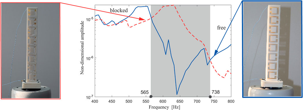
FIGURE 9. Experimentally obtained amplitude-frequency response curve of the metastructure with eight internal blocked (red dashed line) and free (blue solid line) internal oscillators.
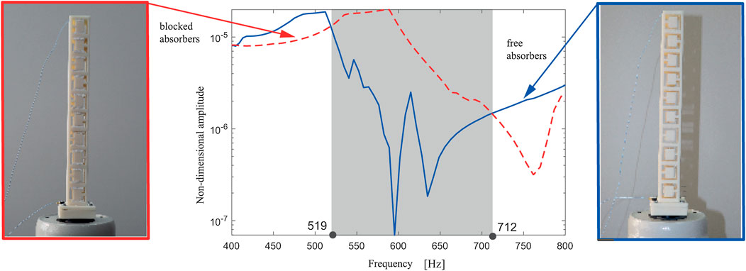
FIGURE 10. Experimentally obtained amplitude-frequency response curve of the metastructure with 10 blocked (red dashed line) and free (blue solid line) internal oscillators.
The previously investigated behavior of the metastructure from [22] with various numbers of internal oscillators, all of which have the same natural frequency, regards the bandgap around the first resonance only, as considered in [22]. However, it is interesting to explore the performance characteristics of the metastructure under consideration in a wider frequency region and at other resonances as well, as this has not been done before for this type of metastructure from [22]. To that end, the metastructure with 10 internal oscillators with the parameters defined in Table 1 is imported and analyzed in the software COMSOL Multiphysics. The dynamic behavior of internal oscillators at various frequencies is analyzed, and it is found that some of them are not as active as would be desirable given their role. This was the motivation to modify them, trying to make them more active, with a general aim to improve the performance characteristics of the metastructure. For the sake of their redesign, the theoretically obtained result for their first angular frequency, Eq. 13, is utilized. It has been decided to change the parameter e—the height of the clamped beam of the internal oscillators (Figure 2A)—as this is the most convenient for practical reasons.
This parameter is changed for the pairs of internal oscillators to create balanced torques in each pair in the static equilibrium position around which they oscillate. The redesign is done using two strategies for creating two new versions of the metastructure (it should be noted that the original version will be labeled as Version 0 subsequently). For the new Version I, the parameter e is increased linearly by 1 mm in each pair. Consequently, following its influence on the fundamental frequency (Figure 11), this yielded the nonlinear increase in the fundamental frequency of the paired internal oscillators, as shown in Table 2. For the new Version II, the fundamental frequency is increased linearly by a constant step between each pair of internal oscillators. Calculating the parameter e from Eq. 13, its nonlinear increase is obtained, as given in Table 2. The other geometric and material parameters of the metastructure are kept constant as in Version 0. As far as the authors are aware, this is a novel idea of how the change of the natural frequency of internal oscillators can be achieved.
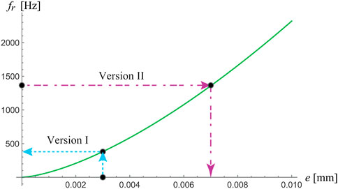
FIGURE 11. Influence of the height of Part 2 (parameter e) on the first bending frequency
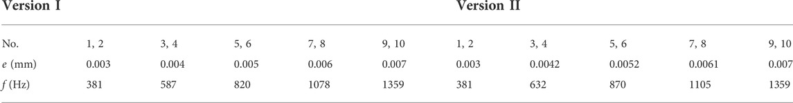
TABLE 2. Modified parameter e of the pairs of internal oscillators (No.) and the corresponding fundamental frequency f in two versions: Version I (linearly increasing e, nonlinearly increasing f) and Version II (linearly increasing f, nonlinearly increasing e).
The corresponding amplitude-frequency response curves for the top of such metastructures are calculated in software COMSOL Multiphysics and plotted together with Version 0 in Figure 12A. Rayleigh damping is chosen as direct input of mass damping parameter of 18.0716 and stiffness damping parameter β of 0.00003 (alternatively, one can define it at two frequencies of 588 and 938 Hz, with the damping ratio of 2.5%). It is seen that both Versions I (cyan dotted line) and Version II (magenta dashed-dotted line) are characterized by considerably lower resonance peaks at the resonances labeled by RA and RB. At resonance RA, the peak amplitude is decreased by 81% in Version I and 49% in Version II. At resonance RB, the peak amplitude decreased more in Version I and Version II. The way how the dynamics of internal oscillators contribute to this reduction is illustrated for both resonances in Figures 12B,C. These presentations enable one to recognize how the new versions employ certain internal oscillators at resonances A and B in terms of their (in)activity and amplitude of vibration.
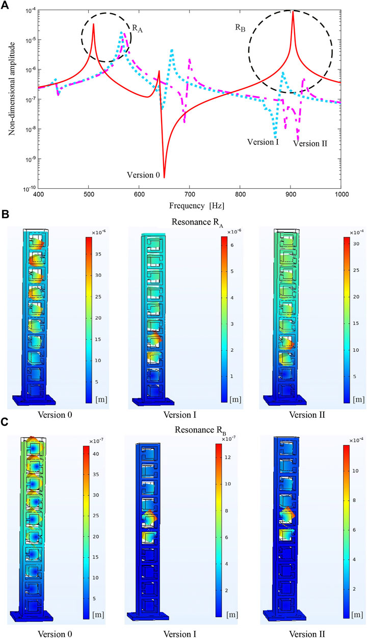
FIGURE 12. Numerically obtained results for the dynamics of internal oscillators for Versions 0, I, and II; (A) amplitude-frequency response curves; (B) presentations of the dynamics at the resonance RA; (C) presentations of the dynamics at the resonance RB.
This study first explored the basic theoretical concept of the use of integrated internal homogenous oscillators that perform transverse oscillations in a metastructure that exhibits longitudinal oscillations. These theoretical considerations have yielded the expressions for the corresponding first modal frequency of the internal oscillators and the metastructure with blocked or free oscillators. Posing the tuning condition that the former and the latter are equal, the required number of internal oscillators has been obtained analytically, and, as far as the authors are aware, this result is novel for the proposed design. This result has also been verified experimentally since the metastructure having such or higher number of internal oscillators showed a considerably wider region in which the amplitude of vibrations is reduced. Besides the benefit related to this attenuation region, the designed metastructures have the first resonant peak reduced and moved to lower frequencies. The theoretical investigations conducted have been used to modify the internal oscillators, achieving either a nonlinear increase in their fundamental frequency or a nonlinear increase in their height, corresponding to the linear increase in their fundamental frequency. The authors believe that this approach to the redesign of the first form of the metastructure from [22] is also original and novel. Such an approach has been utilized and incorporated into COMSOL Multiphysics, providing the proof of concept regarding the better-exploited dynamics of internal oscillators for vibration attenuation at other modal frequencies, thus, improving its multi-modal behavior. Further, the redesigned metastructures can further be utilized for three-dimensional vibration suppression as done in [24] and also as made from metal, which will be done in future research.
The raw data supporting the conclusions of this article will be made available by the authors without undue reservation.
IK: conceptualization, methodologies, writing—review and editing. ZR: theoretical analysis, writing. ZK: preparation for practical realization, experimental analysis, manuscript formatting, and preparation. VR: preparation for experiments, practical realization, numerical analysis.
This paper is the result of the research project “Noise and Vibration Isolation through Nonlinear Metastructures” (NOLIMAST), funded by the Ministry of Education, Science and Technological Development of the Republic of Serbia.
The authors declare that the research was conducted in the absence of any commercial or financial relationships that could be construed as a potential conflict of interest.
All claims expressed in this article are solely those of the authors and do not necessarily represent those of their affiliated organizations or those of the publisher, the editors, and the reviewers. Any product that may be evaluated in this article, or claim that may be made by its manufacturer, is not guaranteed or endorsed by the publisher.
The non-dimensional spatial function is taken in the following form:
where
The effective stiffness and separate masses are obtained as follows (please note that the overall mass M* is their sum):
1. Alati N, Failla G, Santini A. Complex modal analysis of rods with viscous damping devices. J Sound Vibration (2014) 333:2130–63. doi:10.1016/j.jsv.2013.11.030
2. Yao SS, Zhou XM, Hu GK. Experimental study on negative effective mass in a 1D mass–spring system. New J Phys (2008) 10:043020. doi:10.1088/1367-2630/10/4/043020
3. Kulkarni PP, Manimala JM. Realizing passive direction-bias for mechanical wave propagation using a nonlinear metamaterial. Acta Mech (2019) 230:2521–37. doi:10.1007/s00707-019-02415-w
4. Yao SS, Zhou XM, Hu GK. Investigation of the negative-mass behaviors occurring below a cut-off frequency. New J Phys (2010) 12:103025. doi:10.1088/1367-2630/12/10/103025
5. Bukhari M, Barr O. Spectro-spatial analyses of a nonlinear metamaterial with multiple nonlinear local resonators. Nonlinear Dyn (2020) 99:1539–60. doi:10.1007/s11071-019-05373-z
6. Chen YY, Barnhart MV, Chen JK, Hu GK, Sun CT, Huang GL. Dissipative elastic metamaterials for broadband wave mitigation at subwavelength scale. Compos Structures (2016) 136:358–71. doi:10.1016/j.compstruct.2015.09.048
7. Xu XC, Barnhart MV, Fang X, Wen JH, Chen YY, Huang GL. A nonlinear dissipative elastic metamaterial for broadband wave mitigation. Int J Mech Sci (2019) 164:105159. doi:10.1016/j.ijmecsci.2019.105159
8. Liu Z, Zhang XX, Mao YW, Zhu YY, Yang Z, Chan CT, et al. Locally resonant sonic materials. Science (2000) 289:1734–6. doi:10.1126/science.289.5485.1734
9. Sheng P, Zhang XX, Liu Z, Chan CT. Locally resonant sonic materials. Physica B: Condensed Matter (2003) 338:201–5. doi:10.1016/s0921-4526(03)00487-3
10. Yu D, Liu Y, Wang G, Zhao H, Qiu J. Flexural vibration band gaps in Timoshenko beams with locally resonant structures. J Appl Phys (2006) 100:124901. doi:10.1063/1.2400803
11. Zhu R, Liu XN, Huang GL, Huang HH, Sun CT. Microstructural design and experimental validation of elastic metamaterial plates with anisotropic mass density. Phys Rev B (2012) 86:144307. doi:10.1103/physrevb.86.144307
12. Zhu R, Liu XN, Hu GK, Sun CT, Huang GL. A chiral elastic metamaterial beam for broadband vibration suppression. J Sound Vibration (2014) 333:2759–73. doi:10.1016/j.jsv.2014.01.009
13. Chen JS, Sharma B, Sun CT. Dynamic behaviour of sandwich structure containing spring-mass resonators. Compos Structures (2011) 93:2120–5. doi:10.1016/j.compstruct.2011.02.007
14. Qureshi A, Li B, Tan KT. Numerical investigation of band gaps in 3D printed cantilever-in-mass metamaterials. Sci Rep (2016) 6:28314. doi:10.1038/srep28314
15. Yu T, Lesieutre GA. Damping of sandwich panels via three-dimensional manufactured multimode metamaterial core. AIAA J (2017) 55:1440–9. doi:10.2514/1.j055039
16. Beli D, Arruda JRF, Ruzzene M. Wave propagation in elastic metamaterial beams and plates with interconnected resonators. Int J Sol Structures (2018) 139-140:105–20. doi:10.1016/j.ijsolstr.2018.01.027
17. Fabro AT, Meng H, Chronopoulos D. Uncertainties in the attenuation performance of a multi-frequency metastructure from additive manufacturing. Mech Syst Signal Process (2020) 138:106557. doi:10.1016/j.ymssp.2019.106557
18. Souza MR, Beli D, Ferguson NS, Arruda JRde F, Fabro AT. A Bayesian approach for wavenumber identification of metamaterial beams possessing variability. Mech Syst Signal Process (2020) 135:106437. doi:10.1016/j.ymssp.2019.106437
19. Wu L, Geng Q, Li Y-M. A locally resonant elastic metamaterial based on coupled vibration of internal liquid and coating layer. J Sound Vibration (2020) 468:115102. doi:10.1016/j.jsv.2019.115102
20. Jiao P. Hierarchical metastructures with programmable stiffness and zero Poisson's ratio. APL Mater (2020) 8:051109. doi:10.1063/5.0003655
21. Gupta V, Adhikari S, Bhattacharya B. Exploring the dynamics of hourglass shaped lattice metastructures. Sci Rep (2020) 10:20943. doi:10.1038/s41598-020-77226-4
22. Hobeck JD, Laurent CMV, Inman DJ. 3D Printing of metastructures for passive broadband vibration suppression. In: Proceedings of the 20th International Conference on Composite Materials; 19-24 July 2015; Copenhagen (2015).
23. Reichl KK, Inman DJ. Lumped mass model of a 1D metastructure for vibration suppression with no additional mass. J Sound Vibration (2017) 403:75–89. doi:10.1016/j.jsv.2017.05.026
24. Essink BC, Inman DJ. Three-dimensional mechanical metamaterial for vibration suppression. Conf Proc Soc Exp Mech Ser (2020) 5:43–8.
25. Chree C. Longitudinal vibrations in solid and hollow cylinders. Proc Phys Soc Lond (1897) 16:304–22. doi:10.1088/1478-7814/16/1/334
26. Cimellaro GP, Marasco S. Introduction to dynamics of structures and earthquake engineering. Cham: Springer (2018). p. 598.
Keywords: metastructure, internal oscillators, longitudinal vibration, vibration attenuation, transverse vibration
Citation: Kovacic I, Rakaric Z, Kanovic Z and Rajs V (2022) Metastructure with integrated internal oscillators of constant, linearly and nonlinearly varying natural frequency. Front. Phys. 10:934998. doi: 10.3389/fphy.2022.934998
Received: 03 May 2022; Accepted: 19 July 2022;
Published: 31 August 2022.
Edited by:
Marco Scalerandi, Politecnico di Torino, ItalyReviewed by:
Yangyang Chen, Hong Kong University of Science and Technology, Hong Kong SAR, ChinaCopyright © 2022 Kovacic, Rakaric, Kanovic and Rajs. This is an open-access article distributed under the terms of the Creative Commons Attribution License (CC BY). The use, distribution or reproduction in other forums is permitted, provided the original author(s) and the copyright owner(s) are credited and that the original publication in this journal is cited, in accordance with accepted academic practice. No use, distribution or reproduction is permitted which does not comply with these terms.
*Correspondence: Zeljko Kanovic, a2Fub3ZpY0B1bnMuYWMucnM=
Disclaimer: All claims expressed in this article are solely those of the authors and do not necessarily represent those of their affiliated organizations, or those of the publisher, the editors and the reviewers. Any product that may be evaluated in this article or claim that may be made by its manufacturer is not guaranteed or endorsed by the publisher.
Research integrity at Frontiers
Learn more about the work of our research integrity team to safeguard the quality of each article we publish.