 Shaohui Jin
 Lanlan Nie1,2*
 Xinpei Lu
- 1State Key Laboratory of Advanced Electromagnetic Engineering and Technology, School of Electrical and Electronic Engineering, Huazhong University of Science and Technology, Wuhan, China
- 2The GBA National Institute for Nanotechnology Innovation, Guangzhou, China
- 3School of Chemical and Biomolecular Engineering, University of Sydney, Sydney, NSW, Australia
Non-thermal atmospheric pressure plasma jets (NAPPJs) using ambient air as the inducer are of particular and desirable interest but with significant challenges. In this study, we report an air APPJ driven by ionization in the afterglow region, resembling noble gas APPJs. A pin-to-nozzle electrode is used for the air plasma jet with a nanosecond-pulsed DC high voltage as the power supply. Results show that the nozzle diameter plays an essential role in forming the air plasma jet. When the nozzle diameter is 3 mm, the air APPJ is driven by ionization in the afterglow region which is proved by the following three phenomena. First, with an exposure time of 0.1 s, an obvious shiny line (the narrow channel plasma) formed by electron accumulation is observed in the jet. The narrow channel becomes much brighter with a grounding pin approaching the nozzle vertically. In comparison, there is no such phenomenon with a 1-mm diameter nozzle. Second, the afterglow region discharge current of the ionization-driven processes is hundreds of mA distinguished from airflow-driven processes, the afterglow region current of which is typically zero. By using E-FISH to measure the electric field in the afterglow region, it can detect the electric field which has a maximum value of 10.5 kV/cm. Third, the intensity of the N2+ band is much stronger with a 3-mm diameter nozzle than with a 1-mm diameter nozzle, indicating that the local electric field plays an important role in the discharge. We expect this study can offer useful guidelines on the design and understanding of ionization-driven air plasma jets.
Introduction
Atmospheric pressure plasma jets (APPJs) capable of producing various reactive species have attracted increasing attention because of their potential applications in plasma medicine and material processing [1–10]. With an output voltage ranging from several thousand volts to several tens of kilovolts, the gas in the dielectric tube will be ionized, which can produce ionizing waves. These ionizing waves are highly repeatable and able to propagate along the dielectric tube under the action of airflow and extend to the surrounding air to form APPJs [11–16]. Unlike other plasma discharges, which can only occur in narrow electrode gaps, plasma jets can be generated in an open space. Such plasma jets are then feasible for processing samples with complex three-dimensional structures such as tubes, teeth, and skin, and are highly warranted in the plasma medicine area [17–19]. When the working gas for the plasma jets is a noble gas such as He and Ar, generally, a low breakdown electric field is required and a stable discharge is observed [20–24]. Noble gas plasma jets have already been studied in most available reports. In recent years, air plasma jets have begun to attract widespread attention.
An air plasma jet contains two regions: the active region and the afterglow region. An air plasma jet is formed by plasma propulsion in the afterglow region. The driving process of the plasma in the afterglow region is mainly studied. It is generally believed that the air plasma in the afterglow region is driven by airflow [25, 26]. The propagation of these air plasmas is determined by the transport of active particles with long life, the charged particles are led out directly through the earth electrode, and the propulsion speed is close to the airflow velocity so it is driven by the airflow [27–29]. To obtain a longer air plasma jet in the afterglow region, increasing the gas flow rate is seemingly the only currently available method. Only in the narrow breakdown gap is the effect of airflow relatively obvious, which thereby greatly limits further applications of such jets. Therefore, for the current study on air plasma jets, although the cost of air is lower and more convenient, its application is greatly limited by weak ionization, the low concentration of active particles, and high gas temperature, especially when the treatment targets are fragile and sensitive such as cells and tissues [30–33].
This study aims at developing a more application-oriented ionization-driven air APPJ. A bare pin-to-nozzle electrode configuration in a dielectric tube to generate the bare metal air plasma jet was used with a short-pulsed DC high voltage as the power. It is found that different from the previous air jet driven by airflow, part of this air jet is driven by ionization [29, 34]. It has the following characteristics: the jet cross-section is larger and longer; the ionization strength becomes stronger, increasing the concentration of active particles; and the gas temperature decreases. Therefore, this study focuses on the “propagation” characteristics of the ionization-driven air APPJ.
Experimental Setup
Figure 1 shows the schematic of the plasma jet device. Air is used as the working gas. The dielectric tube is made of quartz. In the middle of the dielectric tube is a metallic pin with a diameter of 2 mm. The inner diameter of the dielectric tube is 38 mm. A horn-like nozzle made of copper is inserted tightly from the right end of the dielectric tube. There are three nozzles with different diameters (1, 2, and 3 mm, respectively). The distance between the pin electrode and the exit of the nozzle is 3 mm. The device is powered by a nanosecond pulse power supply directly connected to the pin electrode, with an adjustable amplitude of 0–10 kV, a repetition frequency of 0–10 kHz, and a pulse width from 100 ns to DC. The nozzle is grounded. A voltage probe (Tektronix P6015A) is used to measure the voltages of the pin electrode and the plasma jet, with a digital oscilloscope (Tektronix MDO3034) recording all the voltage waveforms. The working gas (air) flow direction is from left to right in the dielectric tube with the flow rate controlled by a mass flow meter (MKS GE50A). The plasma photographs are captured by a camera (Canon D7000) with an exposure time of 0.1 s. An intensified charge-coupled camera detector (ICCD) is used to capture the air plasma jet’s dynamics photos. A half-meter spectrometer (Princeton Instruments, Acton SpectraHub 2500i) was used to measure the optical emission spectrum of the discharge.
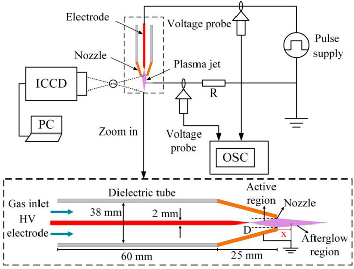
FIGURE 1. Schematic of the air plasma jet device.
Experimental Results
Visible Properties of Air Plasma Jets With Nozzles of Different Diameters
As shown in Figure 2, the different phenomena of the air plasma jet ejected from the nozzle with diameters of 3 and 1 mm are presented, respectively. Clearly, in Figure 2A, an obvious shiny line (the narrow channel plasma) in the central region of the plasma jet with a 3-mm diameter nozzle can be observed. In comparison, the jet from the nozzle with a diameter of 1 mm does not have such a phenomenon, as shown in Figure 2C. To have a deeper insight into this difference, a grounding pin is extended vertically into the air plasma jet to influence the electric field of the afterglow region. As shown in Figures 2B,D, when the distance between the grounding pin and the nozzle is 2 mm, the narrow channel in the central region of the plasma jet with a 3-mm diameter nozzle becomes much brighter, while no visible change can be observed in the plasma jet with a 1-mm diameter nozzle.
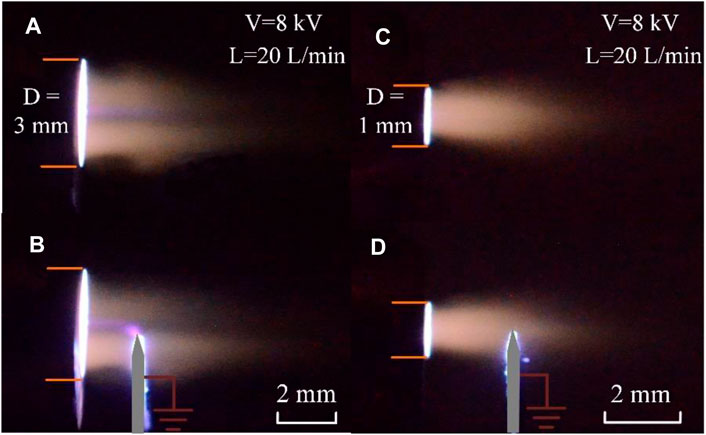
FIGURE 2. Optical photos of the air plasma jet with different diameters nozzles. The nozzle diameter is 3 mm in (A,B) and 1 mm in (C,D). The distance between the pin tip and the nozzle center is 2 mm in (B,D). The airflow rate of air is 20 L/min. The amplitude of the voltage is 8 kV.
Discharge Voltage and Current Characteristics
The discharge voltage and current of the air plasma jet with a 3-mm diameter nozzle are measured. The voltage amplitude is set to 8 kV and the voltage pulse width is set to 250 ns. As shown in Figure 3, with the increase of the applied voltage amplitude, the voltage maintained the pulse waveform until the discharge gap is broken down. When the voltage amplitude rises to 8 kV, the voltage pulse width is reduced to about 130 ns(Figure 3B). The discharge current can be obtained by measuring the displacement current and the total current. The displacement current is measured, as shown in Figure 3A. The measurement result of the total current is shown in Figure 3B. It can be seen that the peak value of the discharge current is very large, which may be due to a large amount of charge flowing directly into the ground electrode.
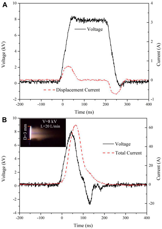
FIGURE 3. Voltage and current waveforms on the pin electrode. (A) Displacement current and (B) total current of the air plasma jet. The airflow rate is 20 L/min. The amplitude of the voltage is 8 kV. The pulse width of the voltage is 250 ns. The frequency of voltage is 5 kHz. The diameter of the nozzle is 3 mm.
The afterglow region of the general air plasma jet cannot measure the current, but there is a bright narrow plasma channel in the air plasma jet of the 3-mm diameter nozzle, which is worth studying. A grounded resistance of 10 kΩ is used to measure the current of the afterglow region. The measuring position is on the same horizontal plane as the jet, and the measuring distance x is the distance between the measuring position and the nozzle outlet. As shown in Figure 4, the measured current became smaller as the measurement distance increased from 2 to 5 mm. Through the small figure in Figure 4, we can see that the phase increases with the measurement distance. The order of magnitude of the current in the afterglow region is confirmed to be 102 mA. This illustrates that there is an electric field in the afterglow region of this air plasma jet. This phenomenon has never been observed and reported before. It is worth mentioning that there is no current in the afterglow region of the air plasma jet with the 1-mm diameter nozzle.
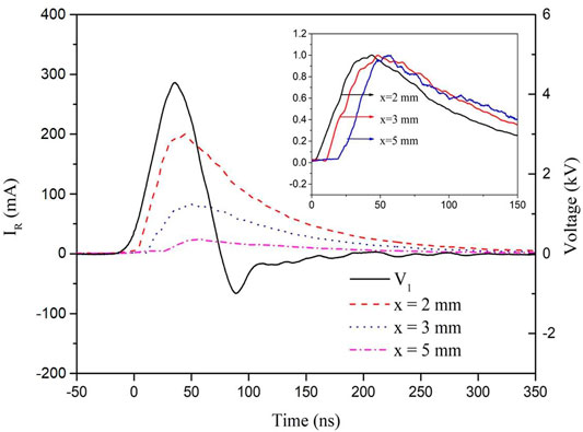
FIGURE 4. Current waveform of the grounded resistance. The resistance is 10 kΩ. V1 is the voltage of the supply. IR is the current on the grounding resistance. x is the distance between the ground resistance pin and the nozzle outlet. The small graph in the upper right corner is obtained by normalizing the waveform of IR with x = 2 mm, x = 3 mm, and x = 5 mm.
Dynamics of the Air Plasma Jet With Different Nozzles
To further understand the propulsion mechanisms of this air plasma jet in the afterglow region, the dynamic of the jet is recorded using a high-speed camera to get high temporal resolution images. For the high-voltage corona discharge with air as the working gas, there are two modes of plasma propulsion. One is the ball-shaped streamers (the plasma bullets) with a velocity of ∼105 m/s. The other one is the uninterrupted plasma plumes with a velocity of ∼102 m/s [35]. From previous works, in the afterglow region, the plasmas in the noble gas jets propagate in the form of plasma bullets, but the plasma in the air jet propagates in the form of the uninterrupted plasma plume. In Figure 5, for the air plasma jet with a 1-mm diameter nozzle, only the uninterrupted plasma plumes can be observed in the afterglow region. The continuous plasma plumes propagate forward gradually, reaching a maximum length at around 70 µs, then weakening until the next discharge. While in Figure 6, which shows the dynamics of the plasma jet with the 3-mm diameter nozzle, when the exposure time is set at 3 ns, the propulsion process of ball-shaped streamers (plasma bullets) from 60 to 120 ns can be captured. At about 110 ns, the plasma bullets reached their peak distance. After 200 ns, with the exposure time adjusted to 1 µs, the uninterrupted plasma plumes can be observed and move forward with a propulsion velocity of ∼50 m/s.
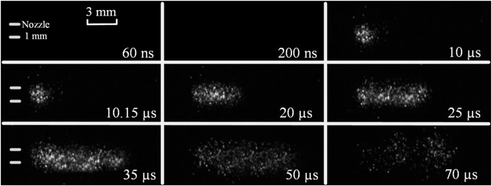
FIGURE 5. Dynamics of the air plasma jet with a 1-mm diameter nozzle in the afterglow region. The exposure time is 1 µs. The time labeled on each image corresponds to the external trigger signal of the fast-speed camera.
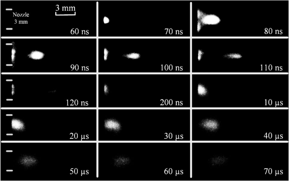
FIGURE 6. Dynamics photos of the air plasma jet with a 3-mm diameter nozzle in the afterglow region. The exposure time is 3 ns in 60∼120 ns and 1 μs in 120∼70 µs, respectively. The time that the external trigger signal gives the camera to start taking pictures is marked in each photo’s bottom right.
According to Figures 5, 6, the position of the plasma plume and the shooting time of each photo can be determined. Therefore, the velocity of the air plasma propagation in the afterglow region can be obtained. The propagation velocity of the plasma with the 1-mm diameter nozzle shown in Figure 5 is calculated to be ∼400 m/s, close to the airflow velocity of 424 m/s, suggesting an airflow-driven propagation. The maximum propagation velocity of the plasma with the 3-mm diameter nozzle (Figure 6) in 60–120 ns is calculated to be 1.34 × 10⁵ m/s, close to that of the plasma bullets with noble gases driven by ionization. In contrast, the velocity of the uninterrupted plasma plumes in 10–70 µs is 50 m/s, approximately close to the airflow velocity of 47 m/s. These results indicate that the air plasma jet with the 3-mm diameter nozzle contains two propulsion processes in the afterglow region, that is, ionization-driven and airflow-driven processes.
Electric Field of the Air Plasma Jets
In order to further prove that there is an ionization-driven process in this air plasma jet with the 3-mm diameter nozzle, electric field–induced second-harmonic generation (E-FISH) has been used to measure the electric field in the afterglow region.
In the experimental system of measuring the electric field by second harmonic, an Nd: YAG–pumped nanosecond pulse laser is used as the fundamental frequency light source, with a working frequency of 10 Hz, a laser pulse width of 7–9 ns, and a laser working wavelength of 1,064 nm. The laser is synchronized with a nanosecond pulse power supply through a Stanford Research System (DG645). The system for the ns E-FISH diagnostic is shown in Figure 7A. A spectrometer connected to an ICCD is used as the detector. Figure 7B shows the plate electrode used in the calibration experiment, and Figure 7C shows the jet structure to measure the electric field.
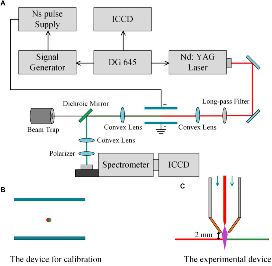
FIGURE 7. System of E-FISH. (A) Schematic of the apparatus for the electric field–induced second-harmonic. (B) Device for calibration. (C) Experimental device.
Two parallel plate electrodes were used for calibration, and the laser passed between the plate electrodes to ensure that the Rayleigh length is in the electrostatic field generated by the electrodes. The distance between the plate electrodes was adjusted so that the air gap distance is 1 cm, different voltages were applied to produce different sizes of uniform electric fields, and the calibration curve was obtained by measuring the second-harmonic signals generated under different electric fields As shown in Figure 8, the linear relationship between the square of the electric field intensity and the second-harmonic signal intensity can be obtained.
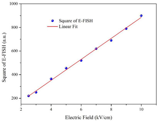
FIGURE 8. Calibration curve of the electric field and square of the second-harmonic signal.
E is the electric field strength. A is the calibration coefficient. IS is the second-harmonic signal strength.
Then, the electric field in the afterglow region of the plasma jet with 3- and 1-mm diameter nozzles was measured, respectively. The laser focusing position was 2 mm below the nozzle. The measured second-harmonic signal intensity is converted into electric field intensity through formula (1). As the result shown in Figure 9, there is no electric field that can be detected in the jet with the 1-mm diameter nozzle, while in the jet with the 3-mm diameter nozzle, the electric field can be detected, and the maximum value is 10.5 kV/cm. It is proved once again that there is an ionization drive in this air plasma jet.
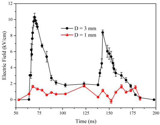
FIGURE 9. Evolution of the electric field with different diameter nozzles.
Optical Emission Spectra of the Air Plasma Jets
Figure 10 shows the spectra of the air plasma jets in the afterglow region. The main emission lines observed are the NO(A-X), N2(B-C), N2+(B-X), N2O, and O atoms in the spectra. Compared with the two nozzles, the similar composition of the active particles and their significantly different shapes and intensities of the spectra were observed. The signal intensity of the spectral band with the 3-mm diameter nozzle is always much stronger than that with the 1-mm diameter nozzle.
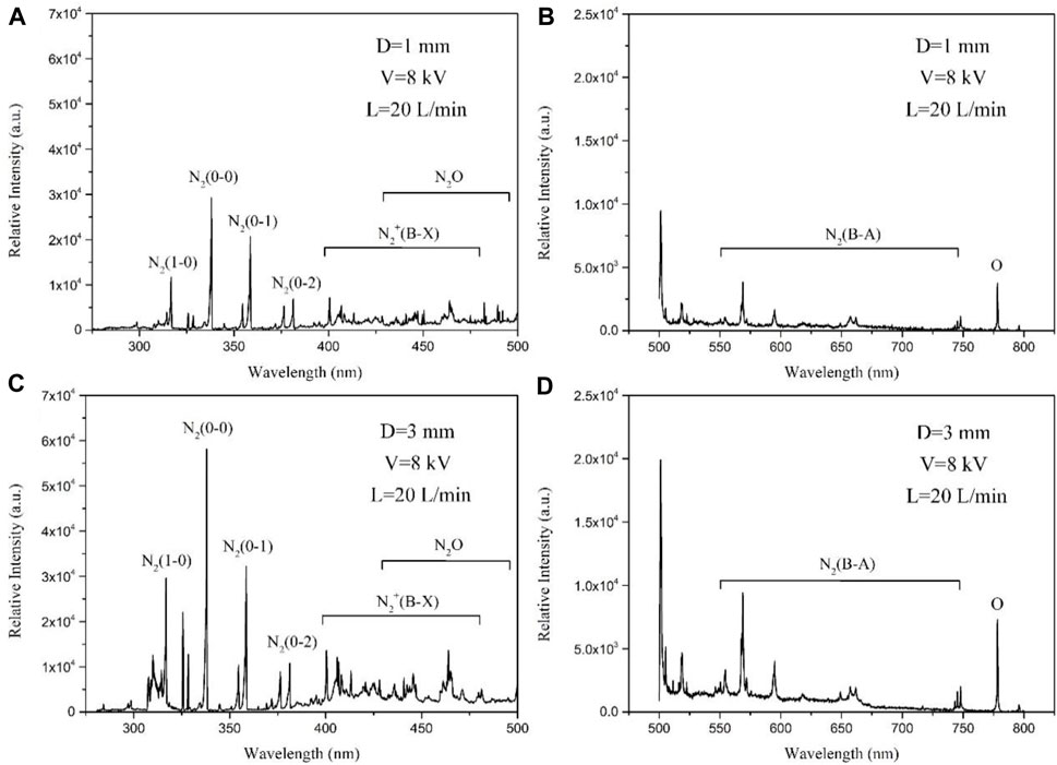
FIGURE 10. Optical emission spectra of plasma jets in the afterglow regions. The direction of the jet is parallel to the slit of the spectrometer. The distance between the sampling position and the nozzle is 2 mm. (A,B) Optical emission spectrum of plasma jets from 300 to 800 nm, D = 1 mm. (C,D) Optical emission spectrum of plasma jets from 300 to 800 nm, D = 3 mm.
Then, the grating of the spectrometer was adjusted to 3,600 g/mm to measure the spectral band near 337 nm. The experimental spectra are fitted with the simulation one to get the rotational temperature. Because of the high collision frequency of the plasma at atmospheric pressure, the rotational temperature is approximately equal to the gas temperature. Figure 11 shows the experimental and simulated spectra of the N2 (337 nm) emission in the afterglow region. For the plasma with the 1-mm diameter nozzle (Figure 11A), the rotational temperature is 330 ± 50 K, while for the plasma with the 3-mm diameter nozzle (Figure 11B), the rotational temperature is 310 ± 50 K in the afterglow region. It is worth mentioning that in the afterglow region, the rotational temperature with the 3-mm diameter nozzle is lower than that with the 1-mm diameter nozzle, which is close to room temperature. This could be linked to the fact that the air plasma jet with the 3-mm diameter nozzle contains an ionization drive process.
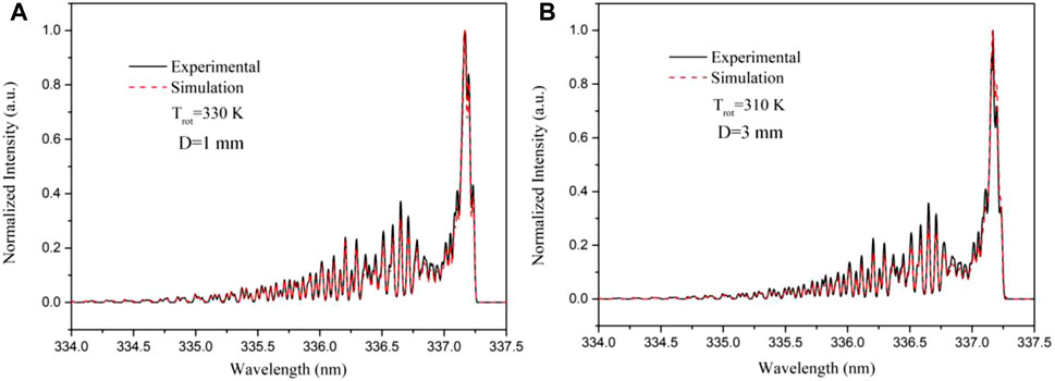
FIGURE 11. Experimental and simulated spectra of the N2 (337 nm) emission. (A) Sampling point is in the afterglow regions, D = 1 mm. (B) Sampling point is in the afterglow regions, D = 3 mm. The simulation spectra are obtained by Specair.
Discussion
It has been generally accepted that the propulsion of the noble gas plasma jets is driven by ionization in the afterglow region [29, 34, 36–38]. The propulsion velocity of the noble gas plasma bullet reaches the order of km/s or even higher. The noble gas is easily broken down, the plasma has high ionization strength, and the gas temperature is close to room temperature. On the contrary, because of the difficulty of air breakdown, the general air jet is generated in the micro-porous structure. The propulsion velocity in the afterglow region is close to the airflow velocity, leading to a great dependence of the air jets on the flow velocity. The gas temperature is high, limiting the application.
In this study, an ionization-driven air plasma jet was obtained by changing the micro-porous structure. The gas temperature was close to room temperature. We observed the propulsion process in the afterglow region of the air plasma jet and obtained three phenomena to illustrate this ionization-driven process.
First, the visible characteristics of the plasma jet with different nozzles are different. An obvious shiny line (the narrow channel plasma) is present in the central region of the plasma jet with the 3-mm diameter nozzle. When the grounding pin approaches the nozzle, it is observed that the narrow channel is significantly brighter. This phenomenon can be explained by the ionization-driving characteristics of the plasma jet. It is proved that there is an electric field in the air jet of the afterglow region, and the intervention of the grounding pin affects the electric field distribution and the propagation of the charged particles. In contrast, the plasma jet with the 1-mm diameter nozzle has not observed the phenomenon.
Second, the dynamic photograph of the plasma jet has been captured. We observed that the plasma jet with the 3-mm diameter nozzle contains two propulsion processes. The plasma advanced quickly with a velocity of about 1.34 × 10⁵ m/s in 60–120 ns and then followed by a much slower velocity in 10–70 µs. While the plasma jet with the 1-mm diameter nozzle only has the airflow-driven process, the plasma propulsion velocity is close to that of airflow.
Why do we choose the airflow rate of 20 L/min? For the ionization-driven process, the gas turbulence causes the instability of gas distribution, resulting in the disorder of plasma bullet propulsion. With the increase of the gas flow rate, the jet length decreases and finally tends to be stable. For the airflow-driven process, the jet length becomes longer with the increase in the gas flow rate, and finally stabilizes at a certain length. Because the air plasma jet introduced in this study includes both an ionization-driven process and gasflow-driven process, when the airflow rate is 20 L/min, the plasma length of both processes can be clearly observed.
Third, the afterglow region’s measured current has indicated the existence of an electric field. According to the measurement of the electric field by E-FISH, the air plasma jet with the 3-mm diameter nozzle has a maximum electric field value of 10.5 kV/cm in the afterglow region, while the jet with the 1-mm diameter nozzle cannot detect an electric field.
Why is there an ionization-driven process in the afterglow region of the air plasma with a 3-mm diameter nozzle? For the ionization-driven process, at least two conditions are needed: the external electric field and the local electric field. In previous reports, the air plasma jets are driven by DC or AC power supply. Now, we use a nanosecond pulse power supply, which makes electrons’ accumulation reach a peak value in a very short time. From the discharge voltage and current curve, the voltage pulse width is set to 250 ns. When the discharge occurs, the voltage and current on the high-voltage electrode mainly exist in the first 100 ns; hence, the ionization strength is relatively high during the first 120 ns of plasma propulsion.
From the point of view of the structure, when the diameter of the nozzles is 1 mm (micro-porous structure), the distance between the high-voltage electrode and the ground electrode is close, and the equivalent capacitance of the nozzle is relatively large. It is equivalent to the high-voltage electrode and the grounding electrode being directly connected through the plasma, and a large amount of charge flows out directly from the grounding electrode, resulting in a high measured current peak. When the diameter of the nozzles is 3 mm, the distance between the high-voltage electrode and the ground electrode becomes larger, and the equivalent capacitance becomes smaller. It causes part of the charge to be ejected with the jet.
Meanwhile, the jet’s spectrum curve also shows that the intensity of N2+ with a 3-mm diameter nozzle is much higher than that with a 1-mm diameter nozzle, proving that the jet can carry an electric-charge strong local electric field.
The aforementioned section can explain why there is an ionization-driven process in the afterglow region. The findings in this study are able to provide much-needed knowledge for the design and fabrication of portable air plasma jets to meet extensive applications in biology and the industry.
Conclusion
In conclusion, this study for the first time confirms the existence of an ionization-driven process in the afterglow region of the air plasma jet with 3-mm diameter nozzles excited by the nanosecond pulse power supply. An ionization-driving process may increase the active properties of the plasma in the afterglow region. The gas temperature is close to room temperature. Achieving this is expected to reduce the air-plasma jet’s dependence on airflow and relieve its confinement by the micro-porous structure. It is beneficial to expand the practical application of these air plasma jets.
Data Availability Statement
The original contributions presented in the study are included in the article/Supplementary Material; further inquiries can be directed to the corresponding author.
Author Contributions
SJ, LN, and XL contributed to the conception and design of the study. SJ, JL, and RZ organized the experiment. SJ analyzed the results of the experiment. SJ wrote the first draft of the manuscript. LN, RZ, and XL wrote sections of the manuscript. All authors contributed to manuscript revision, read, and approved the submitted version.
Funding
This work was partially supported by the National Natural Science Foundation of China (Grant Nos: 51625701, 51977096, and 11805075).
Conflict of Interest
The authors declare that the research was conducted in the absence of any commercial or financial relationships that could be construed as a potential conflict of interest.
Publisher’s Note
All claims expressed in this article are solely those of the authors and do not necessarily represent those of their affiliated organizations, or those of the publisher, the editors, and the reviewers. Any product that may be evaluated in this article, or claim that may be made by its manufacturer, is not guaranteed or endorsed by the publisher.
References
1. Wu S, Cao Y, Lu X. The State of the Art of Applications of Atmospheric-Pressure Nonequilibrium Plasma Jets in Dentistry. IEEE Trans Plasma Sci (2016) 44:134. doi:10.1109/tps.2015.2506658
2. Sousa JS, Niemi K, Cox LJ, Algwari QT, Gans T, O’Connell D. Cold Atmospheric Pressure Plasma Jets as Sources of Singlet delta Oxygen for Biomedical Applications. J Appl Phys (2011) 109:123302. doi:10.1063/1.3601347
3. Laroussi M, Lu X, Keidar M. Perspective: The Physics, Diagnostics, and Applications of Atmospheric Pressure Low Temperature Plasma Sources Used in Plasma Medicine. J Appl Phys (2017) 122:020901. doi:10.1063/1.4993710
4. Ichiki T, Taura R, Horiike Y. Localized and Ultrahigh-Rate Etching of Silicon Wafers Using Atmospheric-Pressure Microplasma Jets. J Appl Phys (2004) 95:35–39. doi:10.1063/1.1630375
5. Shao T, Yang W, Zhang C, Niu Z, Yan P, Schamiloglu E. Enhanced Surface Flashover Strength in Vacuum of Polymethylmethacrylate by Surface Modification Using Atmospheric-Pressure Dielectric Barrier Discharge. Appl Phys Lett (2014) 105:071607. doi:10.1063/1.4893884
6. Li C, Hu J, Lin C, He J. The Control Mechanism of Surface Traps on Surface Charge Behavior in Alumina-Filled Epoxy Composites. J Appl Phys (2016) 49:44. doi:10.1088/0022-3727/49/44/445304
7. Kaushik NK, Ghimire B, Li Y, Adhikari M, Veerana M, Kaushik N. Biological and Medical Applications of Plasma-Activated media, Water and Solutions. Biol Chem (2018) 400:39–62. doi:10.1515/hsz-2018-0226
8. Ghimire B, Szili EJ, Patenall BL, Lamichhane P, Gaur N, Robson AJ, et al. Enhancement of Hydrogen Peroxide Production from an Atmospheric Pressure Argon Plasma Jet and Implications to the Antibacterial Activity of Plasma Activated Water. Plasma Sourc Sci. Technol. (2021) 30:035009. doi:10.1088/1361-6595/abe0c9
9. Ghimire B, Lamichhane P, Lim JS, Min B, Paneru R, Weltmann K-D, et al. An Atmospheric Pressure Plasma Jet Operated by Injecting Natural Air. Appl Phys Lett (2018) 113:194101. doi:10.1063/1.5055592
10. Kazak AV, Kirillov AA, Simonchik LV, Nezhvinskaya OE, Dudchik NV. Inactivation of Consortiums of Microorganisms by Air Plasma Jet at Atmospheric Pressure. Plasma Med (2017) 7:109–15. doi:10.1615/plasmamed.2017019263
11. Lu X, Ostrikov K. Guided Ionization Waves: The Physics of Repeatability. Appl Phys Rev (2018) 5:031102. doi:10.1063/1.5031445
12. Jiang C, Lane J, Song ST, Pendelton SJ, Wu Y, Sozer E, et al. Single-electrode He Microplasma Jets Driven by Nanosecond Voltage Pulses. J Appl Phys (2016) 119:083301. doi:10.1063/1.4942624
13. Jiang N, Ji A, Cao Z. Atmospheric Pressure Plasma Jet: Effect of Electrode Configuration, Discharge Behavior, and its Formation Mechanism. J Appl Phys (2009) 106:013308. doi:10.1063/1.3159884
14. Lu X, Naidis GV, Laroussi M, Ostrikov K. Guided Ionization Waves: Theory and Experiments. Phys Rep (2014) 540:123–66. doi:10.1016/j.physrep.2014.02.006
15. Norberg SA, Johnsen E, Kushner MJ. Helium Atmospheric Pressure Plasma Jets Touching Dielectric and Metal Surfaces. J Appl Phys (2015) 118:013301. doi:10.1063/1.4923345
16. Wu S, Lu X, Pan Y. On the Mechanism of Acceleration Behavior of Plasma Bullet. Phys Plasmas (2014) 21:073509. doi:10.1063/1.4890490
17. Wu F, Li J, Liu F, Zhou X, Lu X. The Effect of Skin Moisture on the Density Distribution of OH and O Close to the Skin Surface. J Appl Phys (2018) 123:123301. doi:10.1063/1.5016203
18. Breden D, Raja LL. Computational Study of the Interaction of Cold Atmospheric Helium Plasma Jets with Surfaces. Plasma Sourc Sci. Technol. (2014) 23:065020. doi:10.1088/0963-0252/23/6/065020
19. Wu S, Liu X, Mao W, Chen W, Liu C, Zhang C. Non-thermal Air Plasma Jets at Atmospheric Pressure: The Flow-dependent Propagation in the Afterglow. J Appl Phys (2018) 124:243302. doi:10.1063/1.5052187
20. Jeong JY, Babayan SE, Tu VJ, Park J, Henins I, Hicks RF, et al. Etching Materials with an Atmospheric-Pressure Plasma Jet. Plasma Sourc Sci. Technol. (1998) 7:282–5. doi:10.1088/0963-0252/7/3/005
21. Cheng C, Liye Z, Zhan R-J. Surface Modification of Polymer Fibre by the New Atmospheric Pressure Cold Plasma Jet. Surf Coat Technol (2006) 200:6659–65. doi:10.1016/j.surfcoat.2005.09.033
22. Kong MG, Kroesen G, Morfill G, Nosenko T, Shimizu T, van Dijk J, et al. Plasma Medicine: An Introductory Review. New J Phys (2009) 11:115012. doi:10.1088/1367-2630/11/11/115012
23. Fridman G, Friedman G, Gutsol A, Shekhter AB, Vasilets VN, Fridman A. Applied Plasma Medicine. Plasma Process Polym (2008) 5:503–33. doi:10.1002/ppap.200700154
24. Wu S, Lu X, Zou D, Pan Y. Effects of H2 on Ar Plasma Jet: From Filamentary to Diffuse Discharge Mode. J Appl Phys (2013) 114:043301. doi:10.1063/1.4816318
25. Deng XL, Nikiforov AY, Vanraes P, Leys C. Direct Current Plasma Jet at Atmospheric Pressure Operating in Nitrogen and Air. J Appl Phys (2013) 113:023305. doi:10.1063/1.4774328
26. Kolb JF, Mohamed A-AH, Price RO, Swanson RJ, Bowman A, Chiavarini RL, et al. Cold Atmospheric Pressure Air Plasma Jet for Medical Applications. Appl Phys Lett (2008) 92:241501. doi:10.1063/1.2940325
27. Hong YC, Uhm HS. Air Plasma Jet with Hollow Electrodes at Atmospheric Pressure. Phys Plasmas (2007) 14:053503. doi:10.1063/1.2736945
28. Pei X, Kredl J, Lu X, Kolb JF. Discharge Modes of Atmospheric Pressure DC Plasma Jets Operated with Air or Nitrogen. J Phys D: Appl Phys (2018) 51:384001. doi:10.1088/1361-6463/aad4e9
29. Xian Y, Wu S, Wang Z, Huang Q, Lu X, Kolb JF. Discharge Dynamics and Modes of an Atmospheric Pressure Non-equilibrium Air Plasma Jet. Plasma Process. Polym (2013) 10:372–8. doi:10.1002/ppap.201200144
30. Walsh JL, Shi JJ, Kong MG. Contrasting Characteristics of Pulsed and Sinusoidal Cold Atmospheric Plasma Jets. Appl Phys Lett (2006) 88:171501. doi:10.1063/1.2198100
31. Pai DZ, Stancu GD, Lacoste DA, Laux CO. Nanosecond Repetitively Pulsed Discharges in Air at Atmospheric Pressure-The Glow Regime. Plasma Sourc Sci. Technol. (2009) 18:045030. doi:10.1088/0963-0252/18/4/045030
32. Walsh JL, Shi JJ, Kong MG. Submicrosecond Pulsed Atmospheric Glow Discharges Sustained without Dielectric Barriers at Kilohertz Frequencies. Appl Phys Lett (2006) 89:161505. doi:10.1063/1.2361274
33. Walsh JL, Kong MG. Portable Nanosecond Pulsed Air Plasma Jet. Appl Phys Lett (2011) 99:081501. doi:10.1063/1.3623487
34. Xian Y, Lu X, Wu S, Chu PK, Pan Y. Are All Atmospheric Pressure Cold Plasma Jets Electrically Driven? Appl Phys Lett (2012) 100:123702. doi:10.1063/1.3696889
35. Tarasenko VF, Baksht EK, Sosnin EA, Burachenko AG, Panarin VA, Skakun VS. Characteristics of a Pulse-Periodic corona Discharge in Atmospheric Air. Plasma Phys Rep (2018) 44:520–32. doi:10.1134/s1063780x18050100
36. Lu X, Laroussi M. Dynamics of an Atmospheric Pressure Plasma Plume Generated by Submicrosecond Voltage Pulses. J Appl Phys (2006) 100:063302. doi:10.1063/1.2349475
37. Lu X, Xiong Q, Xiong Z, Hu J, Zhou F, Gong W, et al. Propagation of an Atmospheric Pressure Plasma Plume. J Appl Phys (2009) 105:043304. doi:10.1063/1.3079503
Keywords: ionization-driven, afterglow region, air plasma jets, pulsed power, electric field
Citation: Jin S, Nie L, Zhou R, Luo J and Lu X (2022) An Ionization-Driven Air Plasma Jet. Front. Phys. 10:928402. doi: 10.3389/fphy.2022.928402
Received: 25 April 2022; Accepted: 18 May 2022;
Published: 24 June 2022.
Edited by:
Vladimir I. Kolobov, CFD Research Corporation, United StatesReviewed by:
Bhagirath Ghimire, University of Alabama in Huntsville, United StatesNatalia Babaeva, Joint Institute for High Temperatures (RAS), Russia
Copyright © 2022 Jin, Nie, Zhou, Luo and Lu. This is an open-access article distributed under the terms of the Creative Commons Attribution License (CC BY). The use, distribution or reproduction in other forums is permitted, provided the original author(s) and the copyright owner(s) are credited and that the original publication in this journal is cited, in accordance with accepted academic practice. No use, distribution or reproduction is permitted which does not comply with these terms.
*Correspondence: Lanlan Nie, bmllbGFubGFuMjAxN0AxNjMuY29t