 He-He Li
 Bo Zheng†
94% of researchers rate our articles as excellent or good
Learn more about the work of our research integrity team to safeguard the quality of each article we publish.
Find out more
ORIGINAL RESEARCH article
Front. Phys., 06 July 2022
Sec. Physical Acoustics and Ultrasonics
Volume 10 - 2022 | https://doi.org/10.3389/fphy.2022.923637
This article is part of the Research TopicAdvances in Phononic and Acoustic MetamaterialsView all 7 articles
Focusing beyond the acoustic diffraction limit has always been expected, especially in acoustic imaging and ultrasonic therapy. Manipulating the acoustic waves beyond the diffraction limit offers an alternative application potential in high-resolution imaging and medical ultrasound diagnosis and treatment. Here, a two-dimensional circular meta-lens is presented, with a sub-wavelength acoustic Helmholtz resonator array to implement the super-diffraction focusing. The proposed acoustic meta-lens consists of 28 units, which possesses the ability to yield designed arbitrary phase shifts and maintain the impedance matching to provide the high sound transmission efficiency. The simulation and experimental results show that the designed acoustic meta-lens can realize subwavelength sound focusing beyond the diffraction limit. The proposed method can greatly promote the application and development of the acoustic superfocusing technology in acoustic imaging, particle manipulation, and other fields.
In recent decades, acoustic focusing technology has been extensively applied in several important fields, including high resolution imaging [1–3], medical ultrasound diagnosis and treatment [4, 5], and acoustic particle manipulation [6–8]. Many researchers regard the effective control of all of the acoustic wave fronts to realize super-diffraction as a key point. Conventionally, in optics, the size of the focal spot is restricted by the diffraction limit, which can be characterized by the Rayleigh criterion [9]. Due to the wave’s exponential decaying nature upon propagation, the light wave carrying rich subwavelength detail information of the object also decays rapidly through the lens. Likewise, the same statement also applies to sound waves. As a result, the size of the sound focal spot is always limited by the diffraction of the Rayleigh criterion.
In order to overcome the diffraction restrictions, substantial efforts have been made in acoustic wave control for focal spots beyond the Rayleigh limit. Acoustical metamaterials provide a powerful tool for the manipulation of sound waves. It was revealed that the acoustic waves can be effectively controlled by these novel methods, such as negative-refractive-indexed [10–12] and hyperbolic-refractive-indexed metamaterials [4, 13–15]. A negative-refractive acoustic meta-lens composed of a honeycomb arrangement of Helmholtz resonant cavities (soda cans) has shown extraordinary physical properties [2], can acquire more detailed information by evanescent waves in the near-field, and is able to break the diffraction limit, achieving super-diffraction imaging. However, on account of its intrinsic volume and dimension, a smaller meta-unit of acoustic regulation is even more promising in actual application [16–18]. Recently, acoustic metamaterials were shown to be able to break through the dimensional limitation to construct subwavelength size unit structures [19–23]. Hyun et al. reported a subwavelength focusing acoustic lens that can focus incident acoustic waves into a subwavelength area beyond the diffraction limit [24]. Shen et al. proposed an amplitude-controlled acoustic super-oscillation hyperlens, breaking the Rayleigh diffraction limit and realizing super-resolution imaging of subwavelength structures [25]. Although the design of acoustic meta-lens for achieving diffractive focusing has been achieved with great success in one-dimension curves, it is still necessary to explore a two-dimensional super-diffraction focus.
In this study, we present a design and realization of a two-dimension circular meta-lens that possesses exceptional capabilities for two-dimensional super-diffraction focus with high transmittance. The meta-lens is composed of many ring-shaped deep subwavelength units that consist of the Helmholtz resonant cavity and the straight tube. To satisfy a full 2π range modulation, four HRs are constructed in series to achieve a wide range of phase shift. Since impedance mismatches can lead to lower transmission, we utilized a straight pipe which is based on the Fabry–Perot resonator at the open side of the HRs to enhance the sound transmission. By adjusting the unit’s structural parameters, the designed acoustic meta-resonant cavity can accurately design and regulate the phase delay of the incident wave. Combining different phase shift units together to construct an acoustic meta-lens can form a focal spot beyond the diffraction limit in a two-dimensional plane.
We constructed the metamaterial structure as an assembly of four fan-like sections of resonators over the whole circle. Each individual section is configured to be composed of 28 units of Helmholtz resonant, shown in Figure 1. The acoustic meta-lens is a circular disk of 298 mm with 28 rings, and the frequency is 3,500 Hz in air. The layer width w is optimized to have a distance of about 0.5 λ; this value can be enough to maintain hybrid resonances. The neck width w2 is approximately 0.022 λ, and the inner diameter width of the air cavity w3 is approximately 0.1 λ. The thickness of the cavity’s walls is approximately 0.015 λ.
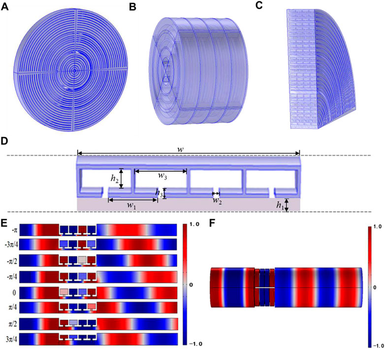
FIGURE 1. Two-dimensional acoustic meta-lens design. (A) Overall sample diagram with a schematic representation of the assembled layer consisting of four fanlike sections of resonators. (B) Schematic representation of a section of the three-dimensional structure. (C) Quarter of the acoustic meta-lens. (D) Hybrid structure consisting of a straight pipe and four Helmholtz resonators (HRs). (E) Simulations of the transmission through eight elements result in an equally increased phase shift with a step of π/4. (F) Transmittance of the simulated third layer unit is 0.84.
HRs provide effective acoustic impedance to control the phase of the incident sound field, but the phase shift of a single HR is limited within a small range [19, 26]. In order to broaden the phase shift range, four HRs connected in series are used as a unit to achieve a larger range of the phase shift. However, the impedance mismatch exists between the Helmholtz cavity and the surrounding medium, which leads to a low transmission efficiency of the sound. The Fabry-Perot resonant straight tube is introduced to match the acoustic impedance. It effectively enhances the sound transmission [27, 28].
We used elements of the hybrid structure to construct the acoustic meta-lens, which is composed of two-dimensional elements and a circular matrix of different radii. Each cell is composed of deep subwavelength Helmholtz resonators (HRs) and Fabry–Perot resonant straight tubes. By adjusting the straight tube of height h1 and the Helmholtz resonator cavity of height h2, and the neck of height h3, the phase and transmittance of the incident wave can be flexibly adjusted. Through eight elements for an equally increased phase shift with a step of π/4, the simulation result that spans the phase shift over a full 2π range is shown. In the simulations of the transmission, we give the sound pressure distribution diagram of the third layer as an example, and its transmittance is 0.84. The third layer is the straight tube of height h1, which is approximately 0.02 λ, the Helmholtz resonator cavity of height h2 is approximately 0.045 λ, and the neck of height h3 is approximately 0.036 λ.
In this study, the pressure acoustics module of COMSOL Multiphysics 5.6 software is used for numerical simulation. The simulations resemble the experimental step of an incident wave at 3,500 Hz (with an airborne wavelength of 98 mm), which uses a plane incident wave to propagate along a cylindrical air waveguide. The density of the background medium air is ρ = 1.21 kg/m3, and the sound velocity is c = 343 m/s. This is because the acoustic impedance of the UV resin is a strong contrast to the acoustic impedance of the air. The walls and the layer of the acoustic meta-lens are regarded as the sound rigid boundaries in the simulation. The 3D printing sample using UV resin material is shown in the following Figure 2A. In order to fix the four-quarter fanlike sections, a solid connection with a fixed angle of four degrees is adopted. The 5-mm solid cylinder in the middle is mainly used for connection, and the purpose is to connect every part and layer of the unit into a whole.
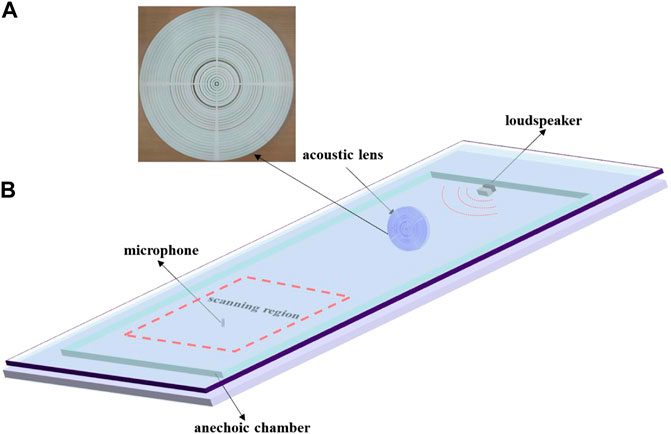
FIGURE 2. Experimental samples of the acoustic meta-lens and the experimental setups. (A) Schematic representation of the two-dimensional fabricated lens. (B) Schematic representation of the experimental setup. The acoustic experiments are conducted in an anechoic chamber. The loudspeaker is used as the source, and a microphone is used to sweep the measured area by using a 3D stepping motor and record the distributions of sound pressure around the acoustic meta-lens.
In order to verify the super-diffraction focusing results in the simulation, experimental illustration and demonstration are conducted in Figure 2B. The sound source is located ten times beyond the wavelength of the designed acoustic meta-lens, and a monochromatic sound wave with a frequency of 3,500 Hz is excited by a loudspeaker to propagate as a plane wave. For the purpose of reducing the impact of the environment and transmitting sound waves, our experiments were carried out in an anechoic chamber. The sound fields are measured in the scanning region using a microphone (1/4-inch) to scan the two-dimensional sound field. The amplitude and phase of the outgoing sound field at each scan point are retrieved from the measurement signal. The mobile microphone and the sound source are, respectively, located on both sides of the units, and the mobile microphone (Brüel and Kaejr type-4958) records the sound pressure of the direction field in the scanning area.
As a basic acoustic system composed of acoustic mass Ma, acoustic capacitance Ca, and acoustic impedance Za, the Helmholtz resonator consists of a sealed cavity with volume V and a short tube with the width a in the neck connected with the outside. The short tube has an acoustic quality and an acoustic impedance, and the air in the short tube is moved under the action of external sound pressure. Its movement drives the air outside the tube to move together. The total air acoustic mass Ma involved in the movement is
which determines the properties of Helmholtz. Therefore, it is extremely important to calculate the resonant frequency of the Helmholtz cavity as accurately as possible. The resonance conditions of the Helmholtz cavity are similar to the resonance conditions in the circuit, and hence, the resonance frequency of the Helmholtz cavity can be expressed as
Based on the cuboid Helmholtz resonant cavity theory in the air [ [29]], the inherent frequency of sound waves in the circular Helmholtz cavity can be precisely derived, as shown in Figure 3. It can be expressed as
where c is the sound speed in the air,
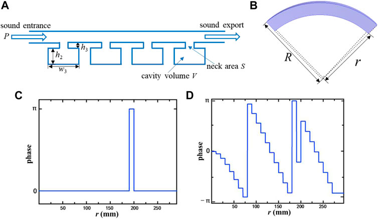
FIGURE 3. (A) Schematic representation of the cubic Helmholtz resonant cavity. (B) Proposed single circular unit layer. (C) Extra binary phase distribution. (D) Discrete phase distribution.
The manipulating of the sound wave is limited by the tradeoff between impedance mismatching and refractive index. For the lumped elements, Helmholtz resonators provide an effective acoustic impedance to change the phase of the incident acoustic field [19, 26].
Each quarter layer of the ring of the designed acoustic meta-lens is composed of four Helmholtz cavities, as shown in Figure 1, and each Helmholtz cavity has the same structural parameters. As a result, each ring consists of the series connection of Helmholtz resonances with the same material and parameters, which produces the phase shift with a large ring. By adjusting the structural parameters of each ring, the discrete phase information can be generated to achieve super-diffraction focusing.
It is assumed that the plane sound is incident on the designed acoustic meta-lens, as illustrated in Figure 4. Based on the generalized Snell’s law, units with discontinuous phase delay can also achieve phase adjustments to the designed wavefront. In the generalized Snell’s law, the parameter describing the phase gradient change
Here, θt and θi are the deflection angle and incident angle of the transmitted wave,
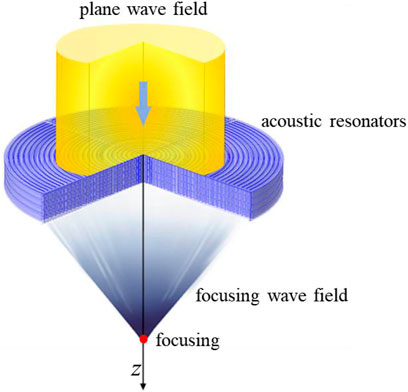
FIGURE 4. Illustration of geometrical requirements necessary to establish an acoustic meta-lens converting an incident plane wave to an outgoing beam with a focusing wave.
Eq. 5 shows that, when the angle of incidence is known, we can arbitrarily control the direction of sound wave propagation by selecting the appropriate phase gradient and thus realize the guidance and control of the sound waves.
Based on the super-diffractive focusing modulation, the phase modulation function of super-diffractive focusing is divided into two parts: the traditional focusing function
where λ is the wavelength of the sound wave, r is the radius of the lens, f0 is the focal length, and m is an integer.
To produce the super diffraction effect, binary high-frequency modulation needs to be added to the focusing function. According to the Fresnel diffraction integral, the transmitted sound field distribution near the focal plane can be expressed as
where r is the distance along the z-axis, and J0 is the Bessel function of order 0. Under paraxial approximation, Eq. 1 can be expressed as
Substituting Eq. 8 into Eq. 7, we obtained the following:
Under the paraxial approximation, λz is kept nearly constant. Therefore, at the acoustic wave wavelength λ0, the sound field distribution on the acoustic super-diffraction focal plane can be expressed as
To perform some kind of super-diffraction focusing, we just have to elaborately design the binary function.
In order to achieve super-diffraction focusing based on Eq. 10, the binary function should be carefully designed. In principle, the central focal spot of the ultra-diffraction focusing can be shrunk to a smaller size, as in Ref. [30–32]. Actually, some of the delicate designed structures cannot be perfectly made by the existing 3D printing technology. As a compromise, an ultra-diffraction focus of 0.428 λ is shown in this study. The extra binary phase distribution is shown in Figure 3C, and the discrete phase distribution is shown in Figure 3D.
From a microscopic point of view, the single unit structure can be considered as a group of modulated and periodic emitters. The incident plane wave is emitted by the sound source and propagates through these mixing units in Figure 4. The sound waves incident on the mixing unit at a specific frequency will produce resonance. Based on the principle of Huygens–Fresnel, each mixing unit can be viewed as a secondary sound source. The transmitted acoustic field is the superposition of all sound waves generated by these secondary sound sources. Assuming that z direction is the spread of sound waves, by adjusting the straight tube of height h1 and the Helmholtz resonators cavity of height h2, as well as the neck of height h3, the incident plane acoustic waves gradually converge to the central axis and will focus on a point on the z axis in Figure 4.
We conducted a series of numerical simulations and experimental verifications to illustrate the performance of the acoustic meta-lens, and the results are shown in Figure 5. From the normalized intensity distribution of the transmitted wave pressure field, both numerical simulation and experimental results exhibit good agreement in the main lobe. The slightly higher and the asymmetric experimental deviation may be caused by fabrication errors and the crude experimental platform.
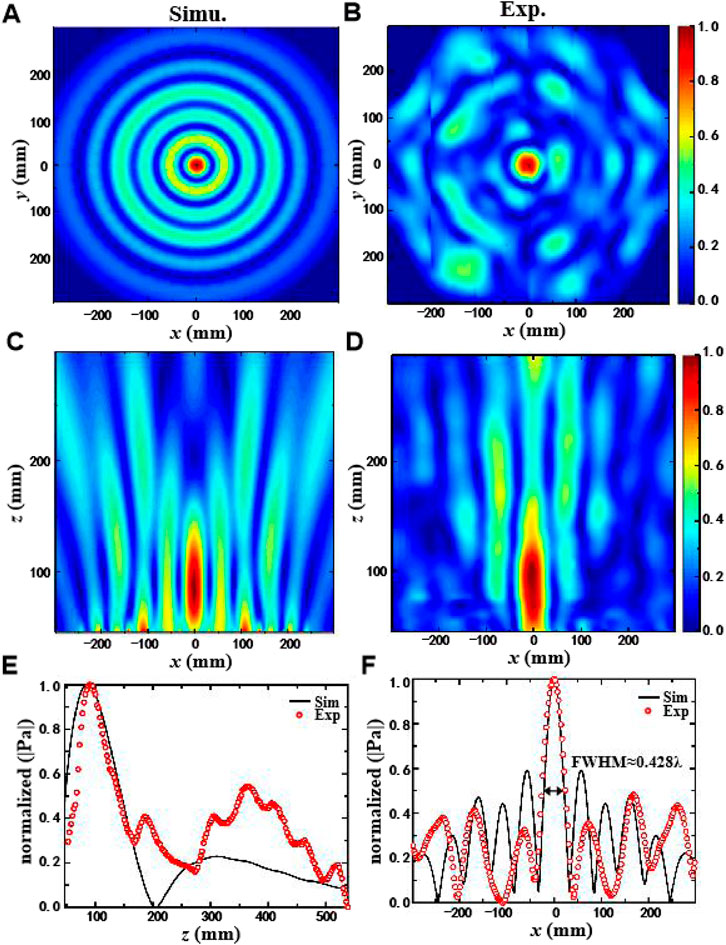
FIGURE 5. Simulation and experimental measurement diagrams of acoustic meta-lens focusing in the air. (A,B) Numerical simulation results and experimental measurement results of the normalized two-dimensional profile of the acoustic meta-lens sound pressure along the z direction. (C,D) Numerical simulation results and the experimental measurement results of the normalized two-dimensional profile of the acoustic meta-lens sound pressure along the x-y plane. (E) Normalized distribution of the simulated sound intensity (black line) and measured sound intensity (red circle) along the z-axis tangent plane with x = 0. (F) Normalized distribution of the simulated sound intensity (black line) and measured sound intensity (red circle) in the focal plane.
To confirm the simulation and experimental results, we theoretically studied the super-diffraction characteristics with low sidelobe features. The energy of the main lobe is higher than the sidelobe in the focusing plane, and the acoustic meta-lens has a subwavelength spatial resolution beyond the diffraction limit. Based on the Rayleigh–Somerfield (RS, Rayleigh-Somerfield) theory in the optical theory system [[33–35]], the formula for the diffraction sound field (z > 0) beyond the acoustic meta-lens structure can be expressed as
Among them, P0 denotes the amplitude of the incident plane wave, and s is the position vector from point (x', y') in plane z = 0 to the point (x, y) in the observation plane.
As anticipated, the location of the focal spot appears at about z = 89 mm away from the center of the acoustic meta-lens in Figure 5E. For quantitative analysis, Figure 5F presents the cross-sectional view of the transmitted pressure field with the normalized intensity distribution on the focal plane. The results of numerical simulation and experimental measurements show that the FWHM (full width at half maximum) measurement is 0.428 λ, which breaks through the Rayleigh diffraction limit.
To summarize, we presented a subwavelength acoustic meta-lens that can efficiently directly manipulate the near-field sound waves. The energy in the center, which is higher than the sidelobe in the focusing plane, and the acoustic meta-lens have subwavelength spatial resolutions beyond the diffraction limit. The unit structure of the designed acoustic meta-lens is a hybrid structure composed of a series of Helmholtz resonators and Fabry–Perot resonance straight tubes. The series connection of Helmholtz resonators yields a large-span phase shift, while the Fabry–Perot resonance maintains impedance matching to enhance sound transmission. The designed lens can break the Rayleigh diffraction limit and form a focal spot in the two-dimensional plane. The experimental results are in good agreement with the simulation results. Moreover, the experimental verification of the designed two meta-lenses has been implemented. The result shows the FWHM of the focal spot is 0.428 λ, which is smaller than the Rayleigh diffraction limit.
The designed lens is particularly remarkable in that the form of the acoustic meta-lens maintains a high transmission while ensuring the overall phase tuning capability. The acoustic meta-lens holds promises for various potential applications, including medical ultrasound imaging and therapy, particle manipulation, super-resolution acoustic microscope, near-field acoustic sensing, and non-destructive testing of alloy material cracks.
The original contributions presented in the study are included in the article/Supplementary Material; further inquiries can be directed to the corresponding authors.
S-CL, X-FC, S-YQ, and X-YL conceived the idea, guided the students, and supervised the project. H-HL, BZ, M-SD, and Y-XH carried out the numerical simulation and theoretical analysis. H-HL, BZ, M-SD, and FH performed the measurement and data processing. H-HL and BZ prepared the manuscript.
This work is supported by the National Natural Science Foundation of China (Grants Nos. 11774081 and 61905069), the Natural Science Foundation of Heilongjiang Province (No. TD2021F001), the Key Research and Development Projects of Heilongjiang Province of China (No. GZ20210029), and the Postdoctoral Science Foundation of China (Grants Nos. 2020T130177 and 2020M670936).
The authors declare that the research was conducted in the absence of any commercial or financial relationships that could be construed as a potential conflict of interest.
All claims expressed in this article are solely those of the authors and do not necessarily represent those of their affiliated organizations, or those of the publisher, the editors, and the reviewers. Any product that may be evaluated in this article, or claim that may be made by its manufacturer, is not guaranteed or endorsed by the publisher.
1. Zhu J, Christensen J, Jung J, Martin-Moreno L, Yin X, Fok L, et al. A Holey-Structured Metamaterial for Acoustic Deep-Subwavelength Imaging. Nat Phys (2010) 7:521–55. doi:10.1038/NPHYS1804
2. Kaina N, Lemoult F, Fink M, Lerosey G. Negative Refractive index and Acoustic Superlens from Multiple Scattering in Single Negative Metamaterials. Nature (2015) 525:77–81. doi:10.1038/nature14678
3. Liu T, Chen F, Liang S, Gao H, Zhu J. Subwavelength Sound Focusing and Imaging via Gradient Metasurface-Enabled Spoof Surface Acoustic Wave Modulation. Phys Rev Appl (2019) 11:3. doi:10.1103/PhysRevApplied.11.034061
4. Li J, Fok L, Yin X, Bartal G, Zhang X. Experimental Demonstration of an Acoustic Magnifying Hyperlens. Nat Mater (2009) 8:931–4. doi:10.1038/NMAT2561
5. Xia J-P, Sun H-X. Acoustic Focusing by Metal Circular Ring Structure. Appl Phys Lett (2015) 106:063505. doi:10.1063/1.4908117
6. Xu Z, Qin L, Xu W, Fang S, Wang J. Design Approach of Perforated Labyrinth-Based Acoustic Metasurface for Selective Acoustic Levitation Manipulation. Sci Rep (2021) 11:1. doi:10.1038/s41598-021-87179-x
7. Memoli G, Caleap M, Asakawa M, Sahoo DR, Drinkwater BW, Subramanian S. Metamaterial Bricks and Quantization of Meta-Surfaces. Nat Commun (2017) 8:8. doi:10.1038/ncomms14608
8. Polychronopoulos S, Memoli G. Acoustic Levitation with Optimized Reflective Metamaterials. Sci Rep (2020) 10:4254. doi:10.1038/s41598-020-60978-4
9. Goodman JW, Cox ME. Introduction to Fourier Optics. Phys Today (1969) 22:97–101. doi:10.1063/1.3035549
10. Pendry JB. Negative Refraction Makes a Perfect Lens. Phys Rev Lett (2000) 85:3966–9. doi:10.1103/PhysRevLett.85.3966
11. Chen M, Xu W, Liu Y, Yan K, Jiang H, Wang Y., Band gap and Double-Negative Properties of a star-structured Sonic Metamaterial. Appl Acoust. (2018). 139.p. 235–42. doi:10.1016/j.apacoust.2018.04.035
12. Li Y, Liang B, Zou X-y., Cheng J-c. Extraordinary Acoustic Transmission through Ultrathin Acoustic Metamaterials by Coiling up Space. Appl Phys Lett (2013) 103:063509. doi:10.1063/1.4817925
13. Fang N, Lee H, Sun C, Zhang X. Sub Diffraction-Limited Optical Imaging with a Silver Superlens. Science (2005) 308. 534–7. doi:10.1126/science.1108759
14. Cai X, Xiao J, Zhang H, Zhang Y, Hu G, Yang J. Compact Acoustic Double Negative Metamaterial Based on Coexisting Local Resonances. App Phy Lett (2018) 113:24. doi:10.1063/1.5052026
15. Smolyaninov II, Hung Y-J, Davis CC. Magnifying Superlens in the Visible Frequency Range. Science (2007) 315:1699–701. doi:10.1126/science.1138746
16. Li C. Study on Elastic Wave Propagation Characteristics of Phonon crystal. Changsha: National University of Defense Technology (2008).
17. Jiménez N, Romero-García V, Pagneux V, Groby J-P. Quasiperfect Absorption by Subwavelength Acoustic Panels in Transmission Using Accumulation of Resonances Due to Slow Sound. Phys Rev B (2017) 95:1. doi:10.1103/PhysRevB.95.014205
18. Yang M, Chen S, Fu C, Sheng P. Optimal Sound-Absorbing Structures. Mater Horizons (2017) 4:4. doi:10.1039/c7mh00129k10.1039/c7mh00129k
19. Li Y, Jiang X, Liang B, Cheng J-c., Zhang L. Metascreen-based Acoustic Passive Phased Array. Phys Rev Appl (2015) 4:2. doi:10.1103/PhysRevApplied.4.024003
20. Li Y, Liang B, Gu Z-m., Zou X-y., Cheng J-c. Reflected Wavefront Manipulation Based on Ultrathin Planar Acoustic Metasurfaces. Sci Rep (2013) 3:3. doi:10.1038/srep02546
21. Zhu Z-H, Sheng L-W, Lv Z-W, He W-M, Gao W. Orbital Angular Momentum Mode Division Filtering for Photon-Phonon Coupling. Sci Rep (2017) 7:7. doi:10.1038/srep40526
22. Jiang X, Li Y, Liang B, Cheng J-c., Zhang L. Convert Acoustic Resonances to Orbital Angular Momentum. Phys Rev Lett (2016) 117:3. doi:10.1103/PhysRevLett.117.034301
23. Zhai S, Chen H, Ding C, Shen F, Luo C, Zhao X. Manipulation of Transmitted Wave Front Using Ultrathin Planar Acoustic Metasurfaces. App Phy A (2015) 120:4. doi:10.1007/s00339-015-9379-6
24. Hyun J, Kim YT, Doh I, Ahn B, Baik K, Kim S-H. Realization of an Ultrathin Acoustic Lens for Subwavelength Focusing in the Megasonic Range. Sci Rep (2018) 8:9131. doi:10.1038/s41598-018-27312-5
25. Shen Y-X, Peng Y-G, Cai F, Huang K, Zhao D-G, Qiu C-W, et al. Ultrasonic Super-oscillation Wave-Packets with an Acoustic Meta-Lens. Nat Commun (2019) 10:3411. doi:10.1038/s41467-019-11430-3
28. Molerón M, Serra-Garcia M, Daraio C. Acoustic Fresnel Lenses with Extraordinary Transmission. Appl Phys Lett (2014) 105:114109. doi:10.1063/1.4896276
29. Qin F, Huang K, Wu J, Teng J, Qiu C-W, Hong M. A Supercritical Lens Optical Label-free Microscopy: Sub-diffraction Resolution and Ultra-long Working Distance. Adv Mater (2017) 29:1602721. doi:10.1002/adma.201602721
30. Shen Y-X, Zhu X-F. Efficient Realization of On-Demand Functional Ultrasonic fields Based on Prolate Spheroidal Wave Functions from Sampling Theorem. The J Acoust Soc America (2022) 151:96–104. doi:10.1121/10.0009048
31. Huang K, Ye H, Teng J, Yeo SP, Luk'yanchuk B, Qiu C-W. Optimization-free Superoscillatory Lens Using Phase and Amplitude Masks. Laser Photon Rev (2014) 8:152–7. doi:10.1002/lpor.201300123
32. Rogers ETF, Lindberg J, Roy T, Savo S, Chad JE, Dennis MR, et al. A Super-oscillatory Lens Optical Microscope for Subwavelength Imaging. Nat Mater (2012) 11:432–5. doi:10.1038/NMAT3280
34. Hu Y, Wang S, Jia J, Fu S, Yin H, Li Z, et al. Optical Superoscillatory Waves without Side Lobes along a Symmetric Cut. Adv Photon (2021) 3:4. doi:10.1117/1.AP.3.4.045002
Keywords: Helmholtz resonators, Fabry–Perot resonant straight tube, acoustic meta-lens, super-diffraction, focusing
Citation: Li H-H, Zheng B, Duan M-S, Han F, Hu Y-X, Li X-Y, Qian S-Y, Chen X-F and Liu S-C (2022) Helmholtz-Structured Two-Dimensional Super-Diffraction Meta-Lens. Front. Phys. 10:923637. doi: 10.3389/fphy.2022.923637
Received: 19 April 2022; Accepted: 18 May 2022;
Published: 06 July 2022.
Edited by:
Yu-Gui Peng, Huazhong University of Science and Technology, ChinaReviewed by:
Yong Li, Tongji University, ChinaCopyright © 2022 Li, Zheng, Duan, Han, Hu, Li, Qian, Chen and Liu. This is an open-access article distributed under the terms of the Creative Commons Attribution License (CC BY). The use, distribution or reproduction in other forums is permitted, provided the original author(s) and the copyright owner(s) are credited and that the original publication in this journal is cited, in accordance with accepted academic practice. No use, distribution or reproduction is permitted which does not comply with these terms.
*Correspondence: Xue-Feng Chen, Y2hlbnh1ZWZlbmdfdmlwQDE2My5jb20=; Sheng-Chun Liu, c2hlbmdjaHVubGl1QDE2My5jb20=
†These authors share first authorship
Disclaimer: All claims expressed in this article are solely those of the authors and do not necessarily represent those of their affiliated organizations, or those of the publisher, the editors and the reviewers. Any product that may be evaluated in this article or claim that may be made by its manufacturer is not guaranteed or endorsed by the publisher.
Research integrity at Frontiers
Learn more about the work of our research integrity team to safeguard the quality of each article we publish.