 Xianghao Li
 Zukun Lu
 Feiqiang Chen
94% of researchers rate our articles as excellent or good
Learn more about the work of our research integrity team to safeguard the quality of each article we publish.
Find out more
ORIGINAL RESEARCH article
Front. Phys., 26 October 2022
Sec. Interdisciplinary Physics
Volume 10 - 2022 | https://doi.org/10.3389/fphy.2022.920967
Traditional anti-jamming algorithms lead to a deviation of the Global Navigation Satellite System receiver’s ranging value, which has become the main obstacle to the improvement of the accuracy of the high-precision ranging receiver. Traditional time-domain anti-jamming (TDAJ) algorithms can cause signal distortion, resulting in ranging bias. This study aims to solve this problem by proposing a design method for adding preprocessing filters in time-domain anti-jamming navigation receivers. In this method, an optimal order filter for adaptively correcting signal distortion is designed according to the time-domain anti-jamming filter coefficients. The experimental results show that the algorithm proposed in this paper can effectively solve the problem of ranging bias caused by the traditional time-domain anti-jamming algorithm. The algorithm can be widely used in dedicated satellite missions that require high positioning accuracy, such as navigation signal monitoring receivers, satellite payload receivers, and precision approach and landing systems for carrier-based aircraft.
The electromagnetic environment of Global Navigation Satellite System (GNSS) has become increasingly complex [1–5]. According to spectrum management and planning, the main frequency band for satellite navigation is in the L-band, but there are also systems such as communication and radar in this frequency band [6]. Therefore, satellite navigation may be subject to unintentional interference [7]. According to the literature [8, 9], the most common type of interference that has the greatest impact on GNSS receivers is narrow-band interference. GNSS navigation receivers using antennae array and single antenna processing have become an important means of anti-jamming [10]. At the same time, because there is no problem of large pseudo-range deviation caused by the mismatch of the amplitude and phase characteristics of the array antenna [11, 12], single-antenna anti-jamming technology exerts its unique advantages in some scenes that require high-precision positioning [13, 14]. High-precision positioning scenarios include navigation signal monitoring receivers, satellite payload receivers, carrier-based aircraft precision approach and landing systems, etc.
Compared with the communication system, the navigation system pays more attention to the ranging performance [15–17]. Thus, in the satellite navigation system, it is necessary to effectively suppress interference while reducing the impact of interference suppression technology on the system ranging performance as much as possible [18, 19]. It has been proved that under the condition of ideal receiver channel characteristics, whether it is a coherent phase detector or a non-coherent phase detector, the code phase tracking loop phase detection result of the navigation signal after the TDAJ filter is unbiased. Thus the TDAJ filter will not bias the pseudo-range measurement results [20].
Unfortunately, channel characteristics are non-ideal in actual situations, and channel non-ideal characteristics are mainly reflected in phase nonlinearity and amplitude non-flatness [21]. The existing anti-jamming filter will cause the receiver pseudo-range measurement bias under the channel non-ideal characteristics [22, 23], and the bias is related to the interference parameters [24, 25]. The bias of the ranging value caused by the interference module has become the main obstacle for the high-precision ranging receiver to improve its accuracy. Therefore, in order to achieve high-precision measurement, researchers have proposed many methods to reduce deviation. A method is to eliminate the non-ideal factors of the receiving channel by adding a calibration filter behind the analog channel. This technology is divided into analog domain equalization technology and digital domain calibration technology [26–28]. The equalization technology in the analog domain generally uses analog components such as inductors and capacitors to build an equalization network, which has the disadvantages of poor equalization accuracy and poor applicability [29, 30]. Calibration techniques in the digital domain usually have high computational complexity and poor precision control. Another type of method uses a small loop self-calibration method to correct the pseudo-range measurement of the receiver [31]. However, the coupling effect of the characteristics of the transmitting channel and the characteristics of the receiving channel may cause the delay correction value to deviate, and this method will add a transmitting channel dedicated to calibration and a receiving channel dedicated to calibration, greatly increasing the hardware the complexity.
Although a great deal of work has been done to study the calibration elimination of deviations, it is still challenging to achieve good anti-jamming performance and high precision ranging [32–37]. In order to solve the above problems, this paper theoretically analyzes the influence of the TDAJ filter on the high-precision measurement of the navigation signal pseudo-range. Because the symmetry of the correlation peak is destroyed when the channel characteristics are not ideal, and the anti-jamming process of the TDAJ filter is the process of accumulation of the correlation function. So the asymmetric correlation peak through the anti-jamming filter will cause more serious distortion. Aiming at the problem of signal distortion caused by the anti-jamming filter, this paper designs an adaptive correction filter according to the filter coefficient of the navigation signal after passing through the anti-jamming module, and preprocesses the local pseudocode signal. The algorithm effectively solves the problem of ranging bias caused by the traditional TDAJ filter.
The rest of this paper is organized as follows. First, the non-ideal channel model and signal model are established in Section 2. Second, a detailed theoretical analysis in Section 3 describes the ranging bias caused by the anti-jamming filter. Then an adaptive correction filter is designed in Section 4, and the optimal order of the filter is theoretically derived. At the same time, Section 4 also analyzes the effect of the algorithm on the carrier-to-noise ratio. Section 5 presents the simulation results of ranging bias compared with traditional algorithms, further demonstrating the effectiveness and robustness of the proposed method. Finally, Section 6 shows the conclusion.
As shown in Figure 1, the mathematical model structure diagram shows that
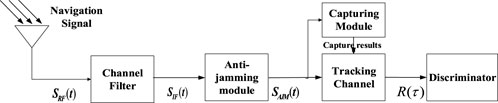
FIGURE 1. Block diagram of mathematical model.
In the simulation experiment, to make use of the measured channel characteristic data, additional channel characteristics can be disturbed according to the method which is shown in Figure 2 [38].
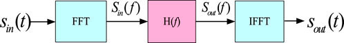
FIGURE 2. A model for adding channel characteristics to interference signals.
In Figure 2,
In engineering applications, the amplitude-phase characteristics of antennas and RF channels can be measured by signal sources and spectroradiometers. Figure 3 shows the measured amplitude-phase characteristics of four single antenna channels measured by signal source and spectrum analyzer. It can be seen from Figure 3A that the magnitude response of the actual channel is non-flat, while it can be seen from Figure 3B that the phase response of the actual channel is nonlinear. The amplitude-phase characteristics of the channel in the simulation experiment will be simulated by using the actual measured data.
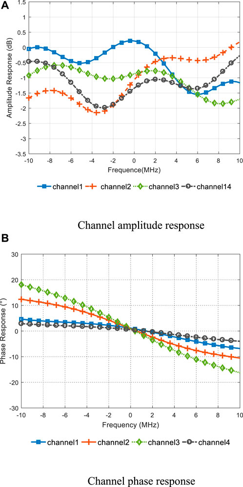
FIGURE 3. Measured amplitude-phase characteristics of single antenna channel. (A) Measured amplitude characteristics of four single-antenna channels, (B) Measured phase characteristics of four single-antenna channels.
The time-domain adaptive anti-jamming technique based on interference estimation is to make use of the difference in predictability between narrowband interference and wideband signal, so as to form the estimated value of narrowband interference, and then cancel it from the received signal to eliminate the narrowband interference.
According to the literature [31], the correlation function after the signal passes through the non-ideal channel is as follows:
where
It can be seen from Eq. 2 that when the navigation signal passes through the non-ideal channel, if the ideal constant amplitude and linear phase filter cannot be guaranteed, the correlation peak will no longer be symmetrical, resulting in distortion and thus affecting the ranging performance.
Figure 4 shows the correlation function when navigation signals pass through ideal channel and non-ideal channel respectively. But from the Figure 4, we cannot intuitively distinguish the difference between the two correlation peaks. Therefore, in the satellite navigation signal channel indicator system, S-curve Bias (SCB), an important indicator, is usually used to measure the symmetry of correlation peaks and quantitatively analyze the ranging bias of receivers [39, 40]. The definition of SCB is expressed as follows, where
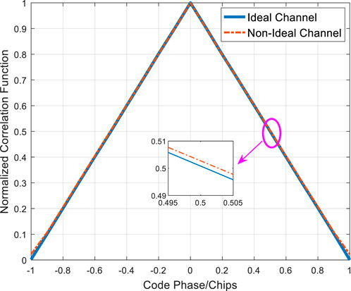
FIGURE 4. Correlation peak comparison between ideal and non-ideal channel characteristics.
In Eq. 3,
As shown in Figure 5, under ideal and non-ideal channel characteristics, the maximum pseudocode ranging deviation exceeds 0.5 ns? Once again it is proved that the error of ranging is caused by the navigation signal passing through the non-ideal channel.
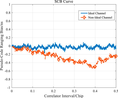
FIGURE 5. SCB comparison diagram for ideal and non-ideal channel characteristics.
In the single-antenna-based interference suppression algorithm, we adopt the time-domain interference suppression based on linear estimation with mature technical basic theory. In this paper, combined with the current situation of engineering implementation, the classical minimum mean square error (LMS) algorithm [41, 42] is selected to provide convenience for the following analysis and application.
In addition, the filter structure adopted in this paper is the common odd-order bilateral tapped transverse filter, namely the filter with interpolation structure. It uses both past and future data to estimate
The order of the filter is (2M + 1). In addition, to prevent the filter coefficient from converging to 0 and facilitate calculation, the intermediate weight of the filter is fixed as 1. In the subsequent studies of this paper, the odd-order bilateral tapped lateral filter is taken as an example for analysis. For an even-order unilateral tapped filter, the local pseudocode signal can be obtained by appropriate delay.
Because the non-ideal characteristics of the receiving channel will distort the correlation peak of the received signal, the correlation peak of the signal input to the adaptive anti-jamming filter no longer meets the requirement of symmetry. In section 2, we have presented the theory and simulation verification. However, in the case of non-ideal channel characteristics, the superposition effect of correlation functions will be generated in the LMS algorithm iteration process when the navigation signals pass through the TDAJ filter, which will aggravate the distortion of correlation peaks and lead to serious bias in ranging. In the following part, the specific analysis will be carried out theoretically.
The structure of the adaptive filter and the implementation of the LMS algorithm are mentioned in Section 2.3. The input of the filter is as follows:
where, the TDAJ filter coefficient
In addition, it has been proved in literature [25] that in the usual way of adaptive filtering, when the filter coefficient meets the conjugate symmetry property, the tracking property of the receiver can be maintained and the SNR loss can be better met. Therefore, when studying the influence of an anti-jamming filter on ranging deviation, the coefficient of the anti-jamming filter is usually kept in conjugate symmetry, as shown in Eq. 6:
Therefore, the discrete output
The output signal after passing through the anti-jamming module is correlated with the local signal
Bring the Eq. 7 into the Eq. 8:
The correlation function of the above formula can be further simplified as:
where,
From the theoretical proof of Eq. 9 and Eq. 10, it can be seen that when the filter coefficient
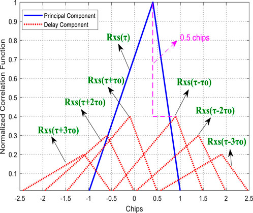
FIGURE 6. Graph of the correlation function of different delay times under a non-ideal channel.
In addition, when the anti-jamming filter coefficient converges,
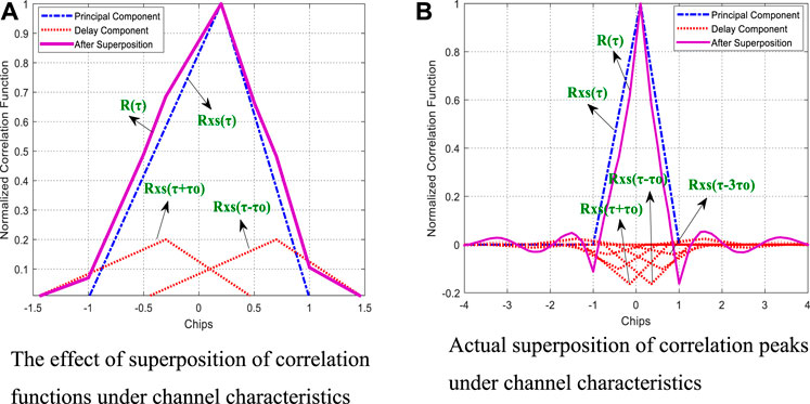
FIGURE 7. The effect of superposition of correlation functions under channel characteristics. (A) A rendering of the superposition of correlation functions under channel characteristics, (B) Actual superposition of correlation functions in traditional LMS algorithm under channel characteristics.
It can be seen from the superposition results of correlation functions on the right of Figure 7. Due to the superposition of correlation functions at different times, the correlation summit after passing through the anti-jamming module under the characteristics of a non-ideal channel will produce more serious distortion, which will affect the range measurement deviation and the SNR, and the real value of filter coefficient convergence obtained by the LMS algorithm in the experiment was used for simulation, and the cumulative correlation peak was obtained as shown in the left of Figure 7.
Aiming at the problem of pseudo-distance deviation caused by the anti-jamming module discussed above, this section will propose a robust adaptive correction algorithm, and theoretically deduce the optimal filter order under this algorithm. The impact of the algorithm will also be analyzed.
The flow chart of the robust ranging algorithm is shown in Figure 8.
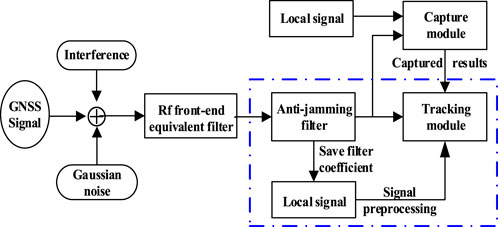
FIGURE 8. Robust ranging algorithm flow chart.
First of all, in order to eliminate the superposition effect of related functions brought by the anti-jamming module in the iterative process, we will design the filter coefficient for preprocessing the local pseudocode according to the anti-jamming filter coefficient, and the specific calculation formula will be given later. The signal output
Then, the navigation signal passing through the anti-jamming filter is correlated with the preprocessed local signal, and its correlation function is expressed as follows:
Substituting Eqs 7, 11 into Eq. 12 can be calculated as follows:
Further calculation of the above related functions can be obtained as follows:
Further considering that when the order of the filter preprocessing the local pseudocode is equal to the order of the anti-jamming filter (that is, when 2L+1 = 2M + 1), the Eq. 14 can be further simplified to obtain:
When the order of the local pseudocode preprocessing filter is equal to the order of the anti-jamming filter (that is, when 2L+1<2M + 1), the Eq. 14 can be further simplified to obtain:
In Section 3 of this paper, it has been deduced and proved that the aggravation of correlation peak distortion is caused by the superposition effect of correlation functions at different moments after the signal passes through the anti-jamming module. Therefore, in Eq. 15 and Eq. 16, we preprocessed the local signal through the filter coefficient
In the form of matrix, the solution to
According to Eq. 16, it not only ensures that the principal component
In the navigation receiver, Early minus Later (E-L) code phase discriminator is used for ranging [28, 29]. In Eq. 19, if the delay component of the correlation function only affects the principal component of the correlation function beyond the E-L code interval, the ranging result will still not be affected. Therefore, when the preprocessed local signals are correlated with the signals passing through the anti-jamming filter, the robust ranging performance can be maintained by eliminating other correlation function delay components within the E-L code interval of the correlation function principal component. The code interval is 2∆, then the optimal order of the preprocessing filter through which the local signal passes is
In Figure 9, when the sampling rate is 20 MHz and the code rate is 10.23MHz, according to Eq. 20, it can be seen that the optimal preprocessing filter order is five orders. It can be seen from the figure that in scenarios with different narrowband interference and correlator intervals, when the preprocessing filter order reaches the theoretically optimal order, the ranging value reaches a stable state, and the optimal order is effective.
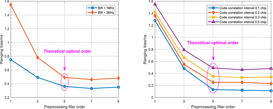
FIGURE 9. Optimal order under different interference scenarios and correlator intervals.
Carrier-to-noise ratio (CNR) is defined as the ratio of signal power to the noise power in a unit bandwidth, and is an important indicator for evaluating signal quality in navigation reception [43]. In order to further derive the loss limit of the CNR of the robust ranging algorithm proposed in Section 4.1, the signal energy loss due to the superposition effect of the correlation function is analyzed from the energy perspective of the correlation domain. In the correlation domain, in the absence of interference and noise, the area of the correlation function in
where,
The total energy loss of the pure navigation signal after passing through the anti-jamming filter can be deduced as:
Then the power of signal loss can be expressed as:
Because of the complexity of the expression of the filter coefficients in the time domain, the coefficients are derived from the ideal band-stop filter in the frequency domain. Assume that the symbols of the input signal, weight value, and output signal in frequency domain anti-jamming are
Focus on analyzing the frequency domain filter
Assuming zero is set on the frequency interval of
In order to prevent the filter coefficient from converging to 0 and to facilitate calculation, the middle tap is usually constrained to one when using a bilateral tapped transverse filter. Then in the time domain, as in Eq. 27, the modulus ratio of the tapped coefficient at
Using Euler’s formula to expand and further simplify:
As shown in Eq. 29,
The signal energy loss is maximum when the delay component of the correlation function is outside the interval
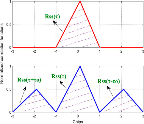
FIGURE 10. Energy diagram of the correlation function.
In Figure 10, the red correlation function at the top is the correlation function before the pure navigation signal passed through the anti-jamming module under the channel characteristics, and the area of the correlation function within the interval
Substitute Eq. 29 into Eq. 23:
By numerical simulation of Eq. 31, it can be seen from Figure 11 that when N is greater than order 10, the CNR loss caused by signal superposition tends to a fixed value of 1.8 dB (one decimal place is reserved). It is concluded that the maximum signal power loss caused by the adaptive correction algorithm is 1.8 dB.
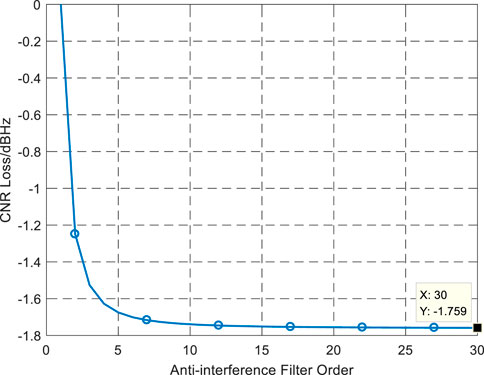
FIGURE 11. CNR loss under different orders.
In this section, the performance of a typical Beidou ranging receiver under different interference conditions will be simulated to analyze the ranging deviation caused by the anti-jamming module, including simulation verification of the optimal order of the ranging algorithm proposed in this paper and performance analysis.
The parameters for this simulation are listed in Table 1. Where ISR represents the interference-to-signal ratio, and CNR represents the carrier-to-signal ratio, and
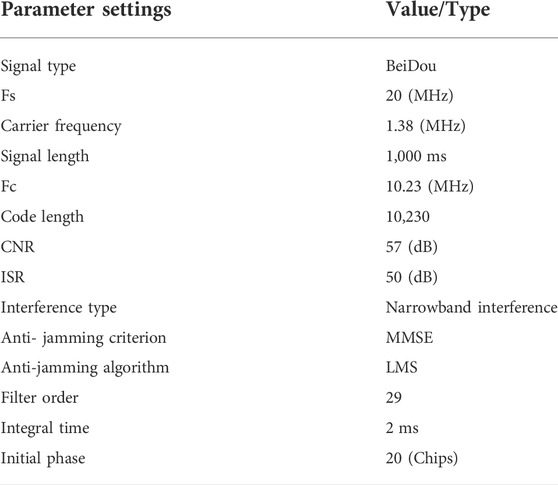
TABLE 1. Simulation parameter setting.
It should be noted that in the following experimental scenarios, the channel characteristics adopt the measured amplitude and phase characteristics shown in Figure 3. In addition, it should be noted that in the following simulation scenarios, the ranging deviation values of the vertical coordinates are based on the ranging values under the condition of no interference.
In Figure 12, according to formula (20), it can be known that the optimal preprocessing filter order is fifth, and from Figure 14, the distorted correlation peaks after passing through the traditional LMS algorithm are all repaired to different degrees after passing through preprocessing filters of different orders. When the preprocessing filter order is greater than or equal to the optimal order, the different delay components of the correlation function cumulative in the correlator interval can be eliminated, so that the distorted correlation peak can be adaptively corrected.

FIGURE 12. The restoration diagram of correlation peaks under the improved algorithm.
In order to better evaluate the ranging deviation at different correlator intervals, the SCB curves of the improved algorithm and the traditional LMS algorithm under different narrow-band interference are drawn. As shown in Figure 13, the blue curve is the deviation caused by the actual channel characteristics without interference. Compared with the traditional LMS algorithm, the proposed algorithm significantly reduces the ranging deviation, and the ranging value of the signal after passing through the non-ideal channel characteristics is also controlled within the index range.
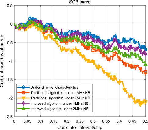
FIGURE 13. SCB curve comparison under different interference scenarios.
In Figure 14, compared with the ranging value of the received signal after passing through the non-ideal channel characteristic, the ranging deviation of the traditional LMS algorithm under different narrowband interference increases with the increase of the interference bandwidth, and it can reach about 1.5ns under 2 MHz narrowband interference. The improved algorithm proposed in this paper corrects the deviation to within 0.5 ns, which conforms to the ranging performance index of the ranging receiver and achieves the effect of robust ranging.
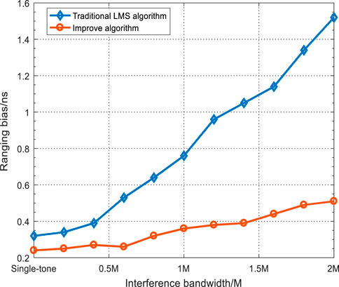
FIGURE 14. Comparison of ranging deviation in different interference scenarios.
In Figure 15, whether under the traditional LMS algorithm or the improved algorithm proposed in this paper, with the increase of interference bandwidth, the loss of the SNR also increases. The SNR loss of the improved algorithm is slightly higher than that of the traditional LMS algorithm, and its loss is less than 1.8 dB in narrowband interference scenarios with different bandwidths, which is consistent with the theoretical analysis in section 4.3.
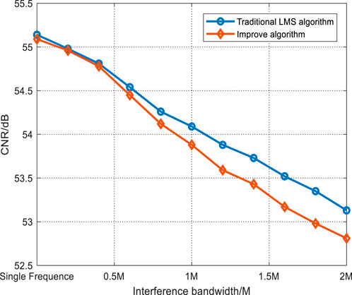
FIGURE 15. CNR comparison under different interference scenarios.
Due to the continuous superposition of the coefficients of the anti-jamming filter, the deviation of the measurement accuracy will be caused under the traditional LMS anti-jamming algorithm. The robust ranging algorithm proposed in this paper designs the corresponding preprocessing filter coefficients according to the anti-jamming filter coefficients. In a typical narrowband interference scenario, the ranging deviation of the traditional LMS anti-jamming algorithm is about 1.5 ns, while the algorithm proposed in this paper corrects the ranging deviation to within 0.5 ns? The simulation results show that the robust adaptive correction algorithm can adaptively correct the signal distortion and effectively reduce the measurement deviation under the optimal preprocessing filter order. At the same time, it can also maintain good anti-jamming performance.
The original contributions presented in the study are included in the article/supplementary material, further inquiries can be directed to the corresponding authors.
XL performed the theoretical study, conducted the experiments, processed the data and wrote the manuscript. ZL designed the system, provided research suggestions and revised the manuscript together with FC, ZL, and YM helped in performing the experiments. GO provided the experiment equipment and suggestions for the manuscript. All authors have read and agreed to the published version of the manuscript.
This research was funded by the National Natural Science Foundation of China (No. 62003354).
The authors would like to thank the editors and reviewers for their efforts to help the publication of this paper.
The authors declare that the research was conducted in the absence of any commercial or financial relationships that could be construed as a potential conflict of interest.
All claims expressed in this article are solely those of the authors and do not necessarily represent those of their affiliated organizations, or those of the publisher, the editors and the reviewers. Any product that may be evaluated in this article, or claim that may be made by its manufacturer, is not guaranteed or endorsed by the publisher.
1. Chen Y, Juang J, Seo J, Lo S, Akos DM, De Lorenzo DS, et al. Design and implementation of real-time software radio for anti-interference GPS/WAAS sensors. Sensors (2012) 12:13417–40. doi:10.3390/s121013417
2. Zhang J, Cui X, Xu H, Lu M. A two-stage interference suppression scheme based on antenna array for GNSS jamming and spoofing. Sensors (2019) 19:3870. doi:10.3390/s19183870
3. Abdulkarim Y, Xiao M, Awl HN, Muhammadsharifd FF, Lang T, Saeed S, et al. Simulation and lithographic fabrication of a triple band terahertz metamaterial absorber coated on flexible polyethylene terephthalate substrate. Opt Mater Express (2022) 12(1):338–59. doi:10.1364/ome.447855
4. Yu X, Yang Q, Xiao Z, Chen H, Havyarimana V, Han Z. A precoding approach for dual-functional radar-communication system with one-bit DACs. IEEE J Sel Areas Commun (2022) 40(6):1965–77. doi:10.1109/jsac.2022.3155532
5. Lu Z, Song J, Huang L, Ren C, Xiao Z, Li B. Distortionless 1/2 overlap windowing in frequency domain anti-jamming of satellite navigation receivers. Remote Sensing (2022) 14:1801. doi:10.3390/rs14081801
6. Hbila J, Biagio F, Astin I, Allbrook T, Arnold A, Vani BC, et al. Performance of GPS positioning in the presence of irregularities in the auroral and polar ionospheres during EISCAT UHF/ESR measurements. Remote Sensing (2021) 13(23):4798. doi:10.3390/rs13234798
7. Xiao W, Wenxiang L, Sun G. Modernization milestone: BeiDou M2-S initial signal analysis. GPS Solutions (2016) 20:125. doi:10.1007/s10291-015-0496-7
8. Lu Z, Nie J, Wan Y, Ou G. Optimal reference element for interference suppression in GNSS antenna arrays under channel mismatch. IET Radar, Sonar & Navigation (2017) 11:1161. doi:10.1049/iet-rsn.2016.0582
9. Lingyu Q, Ying L. Significant wave height estimation using multi-satellite observations from GNSS-R. Remote Sensing (2021) 13(23):4806. doi:10.3390/rs13234806
10. Rusu A, Marghescu I, Lohan S. Impact of narrow band interference on unambiguous acquisition approaches in Galileo. In: Proceedings of Internatianal Conference on Localization & GNSS. Tampere, Finland: IEEE (2021). p. 127–32.
11. Lu Z, Chen H, Chen F, Nie J, Ou G. Blind adaptive channel mismatch equalisation method for GNSS antenna arrays. IET Radar Sonar & Navigation (2018) 12(4):383–9. doi:10.1049/iet-rsn.2017.0416
12. Lu Z, Nie J, Chen F, Chen H, Ou G. Adaptive time taps of STAP under channel mismatch for GNSS antenna arrays. IEEE Trans Instrum Meas (2017) 66(11):2813–24. doi:10.1109/tim.2017.2728420
13. Kalantari M, Li W, Shirinabadi H, Fotowat-Ahmady A, Yue CP. A W-band single-antenna FMCW radar transceiver with adaptive leakage cancellation. IEEE J Solid-state Circuits (2021) 2021:1655–67. doi:10.1109/JSSC.2020.3032677
14. Qi L, Wang Y, Guo Q, Xiang J. Modulation period resampling technique against multiple PFM interferers for single antenna GNSS receivers. IEEE Commun Lett (2020) 24:2309–13. doi:10.1109/LCOMM.2020.3000478
15. Weiming T, Yangyang L, Deng C, Zou X, Wang Y, Qi K. Stability analysis of position datum for real-time GPS/BDS/INS positioning in a platform system with multiple moving devices. Remote Sensing (2021) 13(23):4764. doi:10.3390/rs13234764
16. Loh-Ming L, Milstein L. Rejection of narrow-band interference in PN spread-spectrum systems using transversal filters. IEEE Trans Commun (1982) 30:925–8. doi:10.1109/TCOM.1982.1095543
17. Zhang Y, Kubo N, Chen J, Wang J, Wang H. Initial positioning assessment of BDS new satellites and new signals. Remote Sensing (2019) 11:1320. doi:10.3390/rs11111320
18. Lu Z, Chen F. High precision pseudo-range measurement in GNSS anti-jamming antenna array processing. Electronics (2020) 9:412. doi:10.3390/electronics9030412
19. Lu Z, Chen F. Impact on anti-jamming performance of GNSS signal bandwidth under channel mismatch used antenna arrays. In: IEEE 5th International Conference on Computer and Communication Systems (ICCCS). Shanghai, China: IEEE (2020). p. 717–22.
20. Zhang T, Zhang X. Effect of frequency domain anti-jamming filter on satellite navigation signal tracking performance. In: Proceedings of the 4th China Satellite Navigation Conference (CSNC 2013) (2013). p. 507–16.
21. Wu J, Tang X. Unbiased interference suppression method based on spectrum compensation. IEICE Trans Commun (2019) E103. doi:10.1587/transcom.2019EBP3046
22. De Lorenzo DS, Lo SC, Enge PK. Calibrating adaptive antenna arrays for high-integrity GPS. GPS solutions (2012) 16:221–30. doi:10.1007/s10291-011-0224-x
23. Rante RL, Vaccaro JJ. Wideband cancellation of interference in a GPS receive array. IEEE Trans Aerosp Electron Syst (2000) 36:549–64. doi:10.1109/7.845241
24. O'Brien AJ, Gupta IJ. Mitigation of adaptive antenna induced bias errors in GNSS receivers. IEEE Trans Aerosp Electron Syst (2011) 47:524–38. doi:10.1109/taes.2011.5705689
25. Huang L, Lu Z, Xiao Z, Ren C, Song J, Li B. Suppression of jammer multipath in GNSS antenna array receiver. Remote Sensing (2022) 14:350. doi:10.3390/rs14020350
26. Keegan RG, Knight JE. Signal receiver with group delay and amplitude distortion compensation. US8837654 (2017).
27. Feng W, Youguang F, Bing M, Li-Min C. Performance analysis and improvement of the equalization algorithm based on fou-rier transform radar channel. Actal electronica Sinica (2006) 2006:1677–80.
29. Fang Y, Junnan G. Clipping noise elimination for OFDM systems by compressed sensing with partially aware support. IEEE Trans Broadcasting (2017) 63:103. doi:10.1109/TBC.2016.2606894
30. Lee KS, Cho YJ, Woo JY, No JS, Shin DJ. Low-complexity PTS schemes using OFDM signal rotation and pre-exclusion of phase rotating vectors. IET Commun (2016) 10:540–7. doi:10.1049/iet-com.2015.0192
31. Li B, Ou G. Study on key techniques of the analog signal channel in high performance satellite navigation receiver. ChangSha: National University of Defense Technology (2017).
32. Song J, Lu Z, Xiao Z, Li B, Sun G. Optimal order of time-domain adaptive filter for anti-jamming navigation receiver. Remote Sensing (2022) 14:48. doi:10.3390/rs14010048
33. Liu Z, Pang J, Liu Y, Wang F. Double strobe technique for unambiguous tracking of TMBOC modulated signal in GPS. IEEE Signal Process Lett (2015) 22(12):2204–8. doi:10.1109/lsp.2015.2470240
34. Chien Y-R. Design of GPS anti-jamming systems using adaptive notch filters. IEEE Syst J (2015) 9:451–60. doi:10.1109/jsyst.2013.2283753
35. Daneshmand S, Jahromi AJ, Broumandan A, Lachapelle G. GNSS space-time interference mitigation and attitude determination in the presence of interference signals. Sensors (2015) 15:12180–204. doi:10.3390/s150612180
36. Amin G, Wang X, Zhang YD, Ahmad F, Aboutanios E. Sparse arrays and sampling for interference mitigation and DOA estimation in GNSS. Proc IEEE (2016) 104(6):1302–17. doi:10.1109/jproc.2016.2531582
37. Daneshmand S, Jafarnia-Jahromi A. A GNSS structural interference mitigation technique using antenna array processing. In: 2014 IEEE 8th Sensor Array and Multichannel Signal Processing Workshop (SAM). A Coruna, Spain: IEEE (2014).
38. Han Q, Pang J, Nie J, Wang F. Influence of interference type upon adaptive GNSS antenna array performance. In: Proceedings of the IEEE/ION Position, Location and Navigation Symposium (PLANS). Monterey, CA, USA: IEEE (2014). p. 1057–64.
39. Feng S, Xu G, Qiao L. Non-coherent unambiguous tracking method for cosine-BOC signals based on an S-curve shaping technique. IEEE Signal Process Lett (2015) 22(6):752–6. doi:10.1109/lsp.2014.2368951
40. Chen H, Jia W, Ren J, Yao M. Unambiguous S-curve shaping technique for multipath mitigation in cosine-BOC signals. IEEE Commun Lett (2012) 16(11):1725–8. doi:10.1109/lcomm.2012.091212.121226
41. Wei Y, Yan Z. Variable tap-length LMS algorithm with adaptive step size. Circuits, Syst Signal Process (2017) 36:2815–27. doi:10.1007/s00034-016-0438-9
42. Shanmugam Y, Subbiya A, Sudhakar M, Harsha Visali D. Design of FIR filter using adaptive LMS algorithm for energy efficient application. J Phys : Conf Ser (2021) 1916:012067. doi:10.1088/1742-6596/1916/1/012067
Keywords: global navigation satellite system (GNSS), ranging receiver, time-domain, antijamming, ranging bias, distortion correction
Citation: Li X, Lu Z, Chen F, Liu Z, Yuan M and Ou G (2022) A time domain anti-jamming processing algorithm for GNSS ranging receiver. Front. Phys. 10:920967. doi: 10.3389/fphy.2022.920967
Received: 19 April 2022; Accepted: 12 September 2022;
Published: 26 October 2022.
Edited by:
Fernando A. Oliveira, University of Brasilia, BrazilReviewed by:
Ying-Ren Chien, National Ilan University, TaiwanCopyright © 2022 Li, Lu, Chen, Liu, Yuan and Ou. This is an open-access article distributed under the terms of the Creative Commons Attribution License (CC BY). The use, distribution or reproduction in other forums is permitted, provided the original author(s) and the copyright owner(s) are credited and that the original publication in this journal is cited, in accordance with accepted academic practice. No use, distribution or reproduction is permitted which does not comply with these terms.
*Correspondence: Zukun Lu, bHV6dWt1bkBudWR0LmVkdS5jbg==; Zhe Liu, bF96QG51ZHQuZWR1LmNu
Disclaimer: All claims expressed in this article are solely those of the authors and do not necessarily represent those of their affiliated organizations, or those of the publisher, the editors and the reviewers. Any product that may be evaluated in this article or claim that may be made by its manufacturer is not guaranteed or endorsed by the publisher.
Research integrity at Frontiers
Learn more about the work of our research integrity team to safeguard the quality of each article we publish.