
95% of researchers rate our articles as excellent or good
Learn more about the work of our research integrity team to safeguard the quality of each article we publish.
Find out more
ORIGINAL RESEARCH article
Front. Phys. , 11 August 2022
Sec. Medical Physics and Imaging
Volume 10 - 2022 | https://doi.org/10.3389/fphy.2022.919787
This article is part of the Research Topic Breakthrough in Particle Therapy: At the Edge of Physics, Biology and Medicine View all 8 articles
 Vivek Maradia1,2*
 David Meer1
 Damien Charles Weber1,3,4
 Antony John Lomax1,2
 Jacobus Maarten Schippers1
 Serena Psoroulas1
In proton therapy, high dose rates can reduce treatment delivery times, allowing for efficient mitigation of tumor motion, as well as increased treatment efficiency and patient throughput. In cyclotron-based facilities, however, high dose rates are difficult to achieve at low-energies. In current facilities, the emittance after the degrader is matched in both transversal planes using circular collimators; this does not provide an optimal matching to the acceptance of the following beamline. However, transmission can be substantially improved by transporting maximum acceptable emittances in the X and Y planes, but at the cost of an elliptical beam shape at the gantry entrance, leading to gantry angle-dependent beam shapes at the isocenter. Here we demonstrate that equal emittances in both planes can be recovered at the gantry entrance using a thin scattering foil, thus ensuring gantry angle-independent beam shape at the isocenter. Using modified beam optics and thin scattering foil placed in the beamline, we demonstrate experimentally that low-energy beam transmission can be increased by a factor of three compared to the currently used beam optics, whilst preserving gantry angle-independent beam shapes, at the cost of a large beam size. We expect that this approach could also bring a similar transmission improvement in other cyclotron-based proton therapy facilities.
Particle therapy has become a serious option in radiotherapy to treat certain types of tumors. However, current challenges in particle therapy are the treatment of moving targets and the relatively long treatment times involved. For pencil beam scanning (PBS) [1–3], interplay effects due to organ motion can result in hot and cold spots in target dose distributions. To overcome these problems, different motion mitigation techniques are used such as breath-hold [4, 5], rescanning [6, 7], or gating [8]. For all these techniques, it is also desirable to have shorter treatment delivery times. Whilst shorter treatment delivery times would anyway be welcome in PBS proton therapy from a cost-effectiveness point of view, they could also substantially ease motion mitigation if a single PBS field could be delivered within a single breath-hold [9]. In PBS proton therapy, treatment delivery time depends on beam-on time and on the dead time (time required to change energy layers and/or lateral position). One way to reduce the treatment delivery time for PBS proton therapy is to increase the intensity of the low-energy beams by improving the transmission of the beam from the cyclotron to the isocenter, thereby reducing beam-on time (the time required to deliver the dose) during treatment delivery.
Most currently active proton therapy facilities use a cyclotron to produce protons at the energies required for therapy. One issue with cyclotron-based facilities is the need to lower the beam energy from the fixed values provided by the accelerator (230/250 MeV) to those needed for treatment (70–230 MeV). Usually, this is obtained by passing the beam through a so-called energy selection system (ESS), in which it passes through a certain thickness of low atomic number material (so-called “degrader”), losing energy until the desired energy is reached. The resulting proton beam then has a symmetric, but large phase space (>30 π*mm*mrad) distribution in both transverse planes. This symmetry however is not fully compatible with an optimal transport through the first quadrupole magnet, which is either horizontally or vertically focusing. As described previously however [10], by modifying the emittance after the ESS such that it is asymmetric, transmission through the subsequent beam line can be substantially improved. For instance, after focusing the beam in the Y-plane using the first quadrupole after the degrader, the vertical beam size behind the second quadrupole is small enough to pass the following bending magnet of the ESS, thus allowing to select higher divergence acceptance in the Y-plane compared to the X-plane. As proposed in [10], such an optimized beamline at our facility transports a maximum of ∼ 65 π*mm*mrad in X-plane (using beam size selection collimator radius of 6.5 mm and beam divergence collimator of 14.4 mm) and ∼ 139 π*mm*mrad in Y-plane (using beam size selection collimator radius of 6.5 mm and beam divergence collimator of 33.3 mm), but at the cost of an elliptical beam shape at the gantry entrance, leading to gantry angle dependent beam shapes at the isocenter. Note, in this work beam sizes, divergences and emittances are expressed as 2-sigma values.
To avoid this, it is ideally required to have the same emittance in both planes by the time the beam gets to the gantry entrance [11].
One way to achieve gantry angle independent beam size at the isocenter with asymmetric emittance is to use the so-called sigma-matrix matching technique proposed in [12, 13]. However, this method was proposed for a synchrotron-based facility where the emittance is in the order of 1-5 π∗mm∗mrad and it could work if there are no beam losses through the gantry. Due to the losses through the gantry, this method is not applicable for cyclotron-based facilities.
In this article, we report on the use of a thin scattering foil, placed in the beamline between the ESS and gantry coupling point (see Figure 1), to achieve equal emittances in both planes, whilst maintaining a high transmission through the beamline and gantry, a method also used in HIMAC synchrotron-based ion beam therapy facility [14–16]. Emittances used in synchrotron-based particle therapy facilities however are in the range of 1-5 π*mm*mrad, while in our case, it is in the range of 60–150 π*mm*mrad. In this work we have performed proof of principle measurements at PSI’s PROSCAN beamline and Gantry two to demonstrate that, also for the large and asymmetric emittances after the degrader proposed in [10] and together with the 2:1 gantry imaging optics investigated in [11], the use of a scattering foil can equalize emittances whilst preserving an improved beam transmission through the whole beam line from cyclotron to isocenter. Additionally, we showed that with the equal emittances in both planes, gantry angle independent beam sizes and shapes can be achieved at isocenter. As our primary goal was to improve the transmission for low-energy beams, all experimental investigations were performed with a 70 MeV beam.
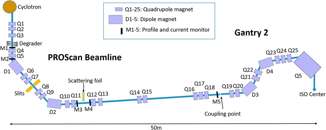
FIGURE 1. Layout of PROSCAN beam line and Gantry 2.
The proposed method uses a thin scattering foil, placed between the ESS and gantry coupling point (Figure 1) to equalize beam emittance between the two transverse planes due to multiple Coulomb scattering in the foil. In each transverse plane, the divergence is the square root of the quadratic sum of the initial divergence (
In which
The scattering contribution required from the foil is determined by requiring the same emittance after the scattering foil in both planes.
From Eq. 2 using (1), the scatter contribution θs is given by (when twiss-parameter α = 0):
Where,
Hence, to increase the emittance in the X-plane to a similar value as the Y-plane emittance, but with minimal effect on the emittance in the Y-plane, the following boundary conditions have been applied:
• The beam waist is at the location of the scattering foil (described in transfer matrix notation as R12 = R21 = 0 and R34 = R43 = 0, α = 0 at degrader, Transfer matrix is from degrader to scattering foil).
• There is no dispersion at the scattering foil location (R16 = R26 = 0, Transfer matrix is from degrader to scattering foil).
• The divergence ratio between X-plane and Y-plane must be smaller than the emittance ratio between X-plane and Y-plane at the entrance of scattering foil.
From Eq. 2 and the initial beam divergences, it can be derived that with
The matrix formalism code TRANSPORT [17] has been used to design new beam optics to include the above described scattering foil. This is based on an optimization of the orientation of the beam’s phase space just before the scattering foil and entrance to the gantry (coupling point). Since transport cannot simulate beams passing through a material, the beam optics have been simulated and optimized independently for the following three sections of the beamline.
1) Degrader to scattering foil,
2) Scattering foil to coupling point, and
3) Coupling point to isocenter.
For all start and end points of each section, the TWISS parameter alpha = 0 and there is no dispersion. To design beam optics between degrader and scattering foil, the above-mentioned boundary conditions have been applied. The gantry beam optics have been designed with 2:1 imaging as described in [11, 18, 19]. This requires a large beam size and low divergence at the entrance of the gantry. The optics are designed such that they provide complete achromaticity of the transported beam in both the beam transport line and in the gantry.
Experimental validation of this proposed approach has been performed on PSI’s PROSCAN beamline and Gantry 2 (Figure 1). An important condition for the experiment was to minimize the modifications of the beamline, so that the patient treatments are not affected. Therefore, the scattering foil has been designed to be retractable and has been installed between two monitors in the beamline (Figure 1) [20]. Before exchanging the monitor (strip chamber monitor which measure the profiles and the current of the beam.) with the scattering foil, the beam size was measured at this location with the new optics designed for the use of scattering foil. Before installing the foil, the emittance at the planned foil location was measured by the quadrupole scanning [21] method using Q11 and monitor M4. Since the scattering foil will have negligible effect on beam size, beam size measurements at monitor M4 with and without scattering foil are used to calculate the divergence of the beam after the scattering foil. Together with the initial divergences, as measured before the foil was inserted, the contribution of the scatterer can then be calculated.
Here, we will discuss the results of our measurements. We will start with the emittance measurement study with and without scattering foil. Then the transmission with the use of scattering foil will be compared to the reference beam optics and the beam size dependency on gantry angle at isocenter presented.
To achieve a similar emittance in both planes after the scattering foil, the beam optics from the degrader exit to the scattering foil (shown in Figure 2) have been redesigned, while still transporting the maximum emittances accepted by the beamline in both planes: 67 π*mm*mrad in X-plane and 139 π*mm*mrad in Y-plane [10]. The beam optics have been designed such that there is a beam waist at the scattering foil location (position two in Figure 3) with a beam size of 9.5 mm and 7 mrad divergence in X-plane, and 5.5 mm and 25 mrad in the Y-plane.
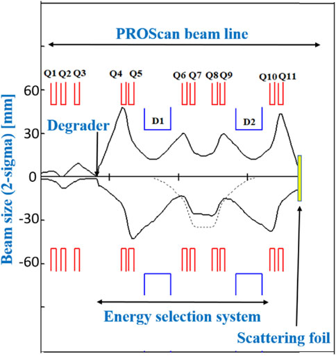
FIGURE 2. New beam optics to achieve beam waist and particular beam phase-space at the entrance of the scattering foil The beam envelopes show the beam size in 2-sigma values and the dispersion (dashed line) along PSI’s ESS beam line (The lower half of figure shows beam envelope in X-plane (bending plane) and the upper half shows envelope in Y-plane). The red line below the quadrupole name and the blue line below the dipole name, represent the element aperture (V above and H below the beam axis).
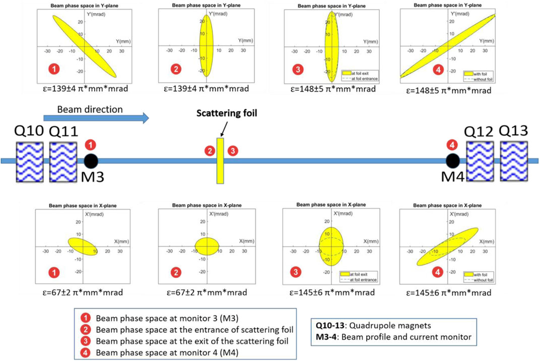
FIGURE 3. Phase space ellipses are shown at (1) 1 m before scattering foil at monitor M3, (2) at the entrance of the scattering foil, (3) at the exit of the scattering foil, and (4) 1.5 m after scattering foil at monitor M4. Transmission improvement with scattering foil.
Due to the use of a very thin foil, beam width is effected only negligibly and therefore is assumed to be 9.5 mm and 5.5 mm in the X- and Y-planes after the scattering foil. Beam divergence could then be deduced by measurement of the beam size at monitor M4 (1.5 m beyond the foil), which were 32.8 mm and 45.0 mm in the X- and Y-planes respectively, from which divergences of 15 mrad and 26 mrad in the X-plane and Y-plane respectively could be derived. This results in almost equal emittances after the scattering foil of 148 π*mm*mrad in the X-plane and 145 π*mm*mrad in the Y-plane (Table 1).
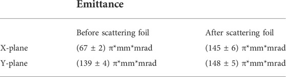
TABLE 1. Measured emittance values just before and after the scattering foil.
The clinically used (reference) beam optics used at our facility for Gantry two were designed to transport only 30 π*mm*mrad (reference beam optics). As such, to transport the 145 π*mm*mrad emittance within the same aperture required to optimize transmission, new beam optics have also been developed from the location of the scattering foil to the gantry isocenter shown in Figure 4.
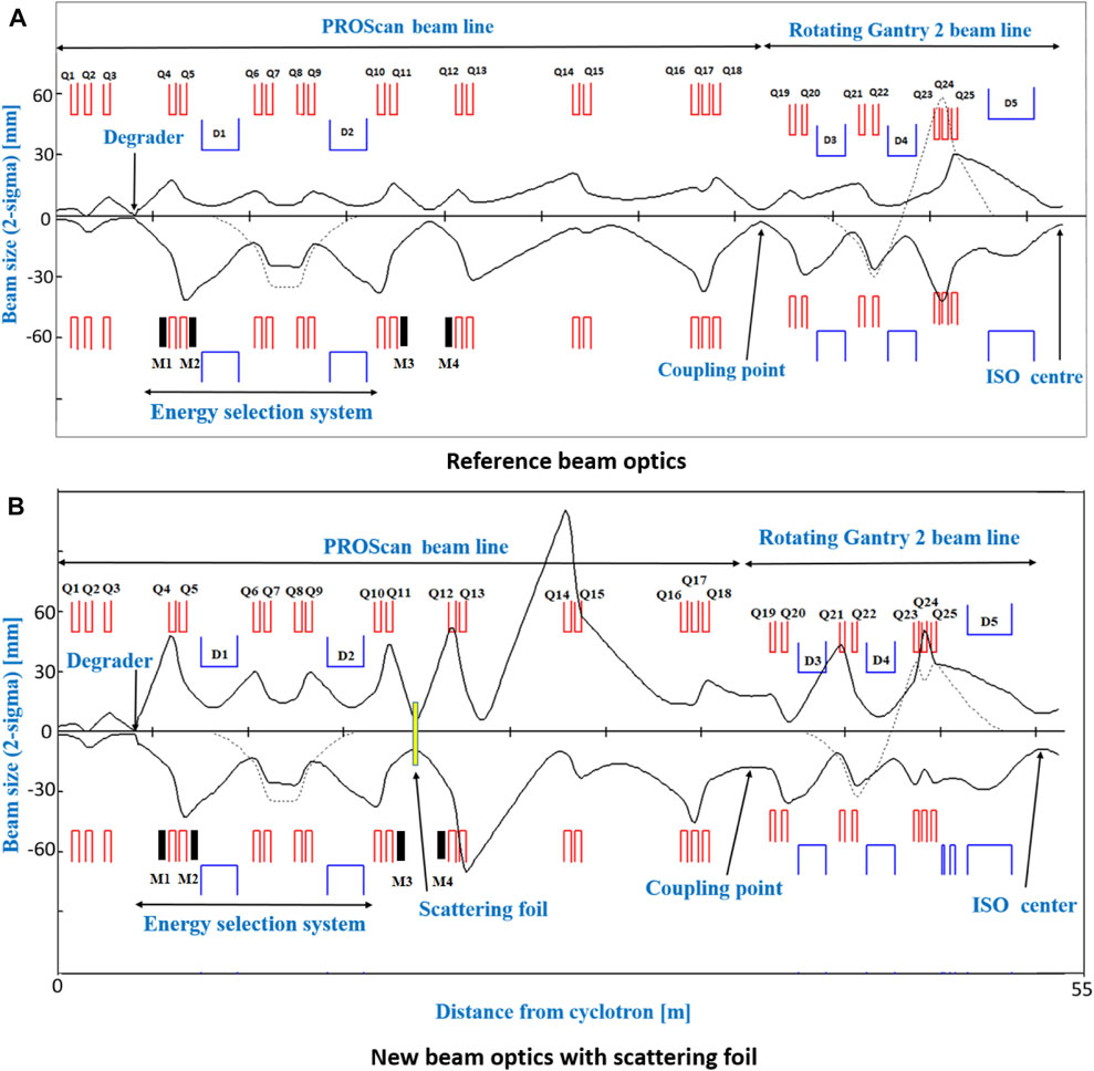
FIGURE 4. (A) Shows reference beam optics transporting 30 π*mm*mrad emittance (in both planes) through beam line and Gantry 2. (B) Shows the new beam optics with scattering foil transporting 67 π*mm*mrad in X-plane and 139 π*mm*mrad in Y-plane up to scattering foil location and transporting almost 145 π*mm*mrad (in both planes) from scattering foil to isocenter. When the beam envelope (beam size) is larger compared to the quadrupole/dipole aperture, beam loss accrued at those locations. Q1-Q18 radius is 50 mm and Q19-Q25 radius is 40 mm. The red line below the quadrupole name and the blue line below the dipole name, represent the element aperture (V above and H below the beam axis).
Between the cyclotron and monitor M2, we lose 95% of the beam intensity using the asymmetric optics compared to 98.5% with the reference beam optics. In addition, when passing through the ESS, the new beam optics achieve a transmission of 1.25% compared to only 0.23% with the reference optics. However, when introducing the scattering foil, divergence increases in both planes and the next quadrupole magnet is almost 2 m away. Therefore, losses between quadrupoles Q12 to Q15 are unavoidable, and another 25% of the beam is therefore lost in the new beam optics. In contrast, there are minimal losses between monitor M3 and coupling point for the reference beam optics. However, the beam optics of the gantry can also be improved using 2:1 imaging [11, 18], allowing to transport higher emittances, once again increasing transmission in comparison to the reference optics. Overall then, with the use of asymmetric optics, 2:1 imaging in the gantry and the introduction of the scattering foil, we measured an overall transmission of 0.4% from the cyclotron to the isocenter, which can be compared to the only 0.13% transmission for the reference beam optics (Table 2). By using the scattering foil, we could thus achieve a maximum of 3.2 nA beam current at the isocenter for a 70 MeV beam (800 nA from cyclotron). This comes at the cost of an increased beam size however. For the reference beam optics, the beam size at the isocenter is (11.2 ± 0.6) mm whereas with the high transmission and scattering foil beam optics, this increases to (20.2 ± 0.8) mm, representing an 80% increase in beam size.

TABLE 2. Measured transmission using reference beam optics and new beam optics with scattering foil. Transmission values are from cyclotron to different locations along the beamline.
In order to simplify beam commissioning and quality assurance, it is desirable to have gantry angle-independent beam optics and beam sizes at the isocenter, and this is the motivation for the scattering foil approach described here. As such, the ratio of measured beam sizes between the X- and Y-planes is shown in Figure 5. When transporting the maximum acceptable emittance in both planes (67 π*mm*mrad in X-plane and 139 π*mm*mrad in Y-plane) without the scattering foil, beam size and shape varies considerably as a function of Gantry angle. However, with the introduction of the scattering foil, similar beam sizes in both planes can be achieved at the isocenter for all gantry angles (Figure 5).
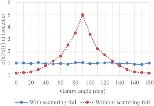
FIGURE 5. Ratio of beam sizes (measured) between X-plane and Y-plane at isocenter for different gantry angles.
In this work, we have demonstrated that by using a thin scattering foil placed in the beam line, we can equalize the emittance in both transverse planes by increasing the divergence in the low emittance-transporting plane. This approach allows to transport the maximum acceptable emittance in both planes after the degrader, while also achieving equal emittance in both planes at the entrance of the gantry. This results in an increase in overall transmission (cyclotron to isocenter) by a factor of three compared to our reference beam optics, as well as gantry angle independence of beam size at isocenter. As all cyclotron-based proton therapy centers have a similar possibility to transport higher emittance in one plane compared to another plane, this approach could be easily adaptable to all other facilities. However, due to the difference in distances, apertures, materials, and cyclotron energies the magnitude of the transmission increase will be facility dependent.
For our experiment, we used the location of one of the beam current monitors to insert a scattering foil, a change that could be implemented easily without interfering clinical operation. For simplicity, and to minimize disturbances to our clinical facility, we inserted the scattering foil in between quadrupole Q11 and Q12 (Figure 1). This however is not an ideal set-up as the first quadrupole (Q12) after the scattering foil is 2 m away. Due to the large divergence after the scattering foil, this causes an almost 25% beam loss between Q12 and Q15. Alternatively, the scattering foil could be inserted just before the quadrupole doublet or triplet so that one could refocus the beam to prevent the losses due to the large divergence after the foil. Therefore, we expect that transmission improvements even larger (∼25% higher) than shown experimentally in this study may be possible. It should also be noted that the scatterer will also have a small effect on beam energy, which will slightly shift the Bragg peak position. To avoid this, one could use a slightly higher incoming beam energy to compensate for this energy loss.
In this work, we have concentrated on the lowest energy that can be transported through our gantry and associated beam line (70 MeV). For higher energy beams however, the emittance in both planes will be different. For such beams, e.g., in the range 170–230 MeV, one would need to redesign the beam optics to achieve the necessary beam phase space at the entrance of the scattering foil to equalize emittance in both planes. On the other hand, since higher energy beams have fewer losses through the beamline and gantry, we could transport different x and y emittances and equalize the emittances by asymmetric focusing at the coupling point collimator, thus equalizing emittances in the x and y planes. This would also add another degree of freedom to reduce the energy-dependent variation of the beam intensity reaching the isocenter.
Finally, as we are transporting higher emittance through the gantry, we have an almost 80% larger beam size compared to the reference beam optics, which may have a detrimental effect on the lateral penumbra. However, at least for motion mitigation, it might be of advantage to have a slightly larger beam size and the beam size measured in this work is still similar to other facilities [22, 23]. Indeed, if a larger beam size could help achieve field delivery times similar to typically achievable breath-hold durations, such degraded lateral penumbras will likely be compensated for by a substantial reduction of size of the ITV (Internal Target Volume) typically required to ensure target coverage. In addition, a larger beam size could be of benefit for reducing the required number of spots in the treatment planning, reducing dead times and therefore also additionally shortening treatment times. Alternatively, it may also be possible to reduce the beam size by redesigning the gantry beam optics using 3:1 imaging [11].
In this article, we report on a method of improving beam transmissions for a cyclotron driven proton therapy facility, which uses a thin scattering foil to equalize emittances in both transverse planes at the coupling point to the gantry. This method substantially increases the low energy beam transmission through the beamline, while achieving gantry angle independent beam sizes at the isocenter. However, transmission increase comes at the cost of beam size. The obtained higher intensities (dose rates) could reduce treatment delivery times to aid motion mitigation techniques such as breath-hold, gating and rescanning. In particular, our work could contribute to reducing delivery times such as to enable single fields to be delivered within a single breath-hold [9]. In addition to improvement in patient comfort, the resulting shorter treatment delivery times could also be of help to increase patient throughput.
The original contributions presented in the study are included in the article/supplementary material, further inquiries can be directed to the corresponding author.
VM designed and carried out the study and wrote the first version of the manuscript. SP and JS are co-investigator of the PSI CROSS grant that funds this research. SP, JS, DM, and AL have significantly revised the manuscript at all stages and supervised the realization of this study in regular meetings. DW managed the funding, reviewed the article. All authors have read and approved the final manuscript.
This work is sponsored by PSI’s CROSS funding scheme. Open access funding provided by Paul Scherrer Institute.
We thank Rudolf Doelling and Christian Baumgarten for their support during the measurements. We acknowledge the help of the PSI cyclotron operation group, PSI vacuum group, and PSI radiation protection group.
The authors declare that the research was conducted in the absence of any commercial or financial relationships that could be construed as a potential conflict of interest.
All claims expressed in this article are solely those of the authors and do not necessarily represent those of their affiliated organizations, or those of the publisher, the editors and the reviewers. Any product that may be evaluated in this article, or claim that may be made by its manufacturer, is not guaranteed or endorsed by the publisher.
1. Pedroni E, Bacher R, Blattmann H, Bohringer T, Coray A, Lomax A, et al. The 200-Mev proton therapy project at the Paul Scherrer Institute: Conceptual design and practical realization. Med Phys (1995) 22(1):37–53. doi:10.1118/1.597522
2. Lin S, Boehringer T, Coray A, Grossmann M, Pedroni E. More than 10 years experience of beam monitoring with the Gantry 1 spot scanning proton therapy facility at PSI. Med Phys (2009) 36(11):5331–40. doi:10.1118/1.3244034
3. Haberer G, Becher W, Schardt D, Kraft. Magnetic scanning system for heavy ion therapy. Nucl Instr Methods Phys. Res. A (1993) 330 (1–2), 296–305. doi:10.1016/0168-9002(93)91335-K
4. Hanley J, Debois MM, Mah D, Mageras GS, Raben A, Rosenzweig K, et al. Deep inspiration breath-hold technique for lung tumors: The potential value of target immobilization and reduced lung density in dose escalation. Int J Radiat Oncology*Biology*Physics (1999) 45(3):603–11. doi:10.1016/S0360-3016(99)00154-6
5. Dueck J, Knopf AC, Lomax A, Albertini F, Persson GF, Josipovic M, et al. Robustness of the voluntary breath-hold approach for the treatment of peripheral lung tumors using hypofractionated pencil beam scanning proton therapy. Int J Radiat Oncology*Biology*Physics (2016) 95(1):534–41. doi:10.1016/j.ijrobp.2015.11.015
6. Mori S, Inaniwa T, Furukawa T, Zenklusen S, Shirai T, Noda K. Effects of a difference in respiratory cycle between treatment planning and irradiation for phase-controlled rescanning and carbon pencil beam scanning. Br J Radiol (2013) 86:20130163–1028. doi:10.1259/bjr.20130163
7. Schätti A, Zakova M, Meer D, Lomax AJ. Experimental verification of motion mitigation of discrete proton spot scanning by re-scanning. Phys Med Biol (2013) 58(23):8555–72. doi:10.1088/0031-9155/58/23/8555
8. Furukawa T, Inaniwa T, Sato S, Shirai T, Mori S, Takeshita E, et al. Moving target irradiation with fast rescanning and gating in particle therapy. Med Phys (2010) 37(9):4874–9. doi:10.1118/1.3481512
9. Maradia V, van de Water S, Meer D, Weber DC, Lomax AJ, Psoroulas S. Ultra-fast pencil beam scanning proton therapy for locally advanced non- small-cell lung cancers : Field delivery within a single breath-hold. Radiother Oncol (2022) 174:23–9. doi:10.1016/j.radonc.2022.06.018
10. Maradia V, Meer D, Weber DC, Lomax AJ, Schippers JM, Psoroulas S. A new emittance selection system to maximize beam transmission for low-energy beams in cyclotron-based proton therapy facilities with gantry. Med Phys (2021) 48(12):7613–22. doi:10.1002/mp.15278
11. Maradia V. A novel beam optics concept to maximize the transmission through cyclotron-based proton therapy gantries. Proc Ipac2021 (2021) 2477–9. doi:10.18429/JACoW-IPAC2021-TUPAB407
12. Pavlovic M. A design of a rotating gantry for non-symmetric ion-therapy beams. Nucl Instr Methods Phys Res Section A: Acc Spectrometers Detectors Associated Equipment (1999) 438(2–3):548–59. doi:10.1016/S0168-9002(99)00828-1
13. Benedikt M, Carli C. Matching to gantries for medical synchrotrons. Proc IEEE Part Accel Conf (1998) 2:1379–81. doi:10.1109/pac.1997.750699
14. Furukawa T, Noda K. Compensation of the asymmetric phase-space distribution for a slowly extracted beam from a synchrotron. Nucl Instr Methods Phys Res Section A: Acc Spectrometers Detectors Associated Equipment (2006) 565(2):430–8. doi:10.1016/j.nima.2006.06.045
15. Furukawa T. “Study of scatterer method to compensate asymmetric distribution of slowly extracted beam at HIMAC synchrotron,” in Proceedings of EPAC2006 Conference. EPAC 2006 - Contrib Proc (2006) 2322–4. Available at: https://accelconf.web.cern.ch/e06/PAPERS/WEPCH167.PDF. no. c.
16. Fujimoto T, Iwata Y, Matsuba S, Fujita T, Sato S, Shirai T, et al. Emittance matching of a slow extracted beam for a rotating gantry. Nucl Instr Methods Phys Res Section B: Beam Interactions Mater Atoms (2017) 406:229–32. doi:10.1016/j.nimb.2017.03.038
17. Brown KL, Carey DC, Iselin C, Rothacker F. Transport, a computer program for designing charged particle beam transport systems. Cern Yellow Rep (1980) 80(04), 1–125. doi:10.5170/CERN-1980-004
18. Maradia V. “New gantry beam optics solution for minimizing treatment time in cyclotron- based proton,” in IPAC Conference Proceeding. Ther Facil (2021), 2477–2479. doi:10.18429/JACoW-IPAC2021-TUPAB407
19. Maradia V, Giovannelli AC, Meer D, Weber DC, Lomax AJ, Schippers JM, et al. Increase of the transmission and emittance acceptance through a cyclotron-based proton therapy gantry. Med Phys (2022) 49(2):2183–92. doi:10.1002/mp.15505
20. Dölling R. “Profile, current, and halo monitors of the PROSCAN beam lines,” in AIP Conference Proceedings (2004) 732:244–52. doi:10.1063/1.1831154
21. Pandit VS, Sarma PR, Bhattacharya S, Bhandari RK. The measurement of the RMS emittance of an ion beam with an arbitrary density profile. Meas Sci Technol (1997) 8(10):1085–9. doi:10.1088/0957-0233/8/10/008
22. Almhagen E, Boersma DJ, Nyström H, Ahnesjö A. A beam model for focused proton pencil beams. Phys Med (2018) 52:27–32. doi:10.1016/j.ejmp.2018.06.007
Keywords: proton therapy, gantry beam optics, high dose rate, efficient treatment delivery, scattering foil
Citation: Maradia V, Meer D, Weber DC, Lomax AJ, Schippers JM and Psoroulas S (2022) Application of a scattering foil to increase beam transmission for cyclotron based proton therapy facilities. Front. Phys. 10:919787. doi: 10.3389/fphy.2022.919787
Received: 13 April 2022; Accepted: 20 July 2022;
Published: 11 August 2022.
Edited by:
Ilaria Rinaldi, Maastro Clinic, NetherlandsReviewed by:
Giulia Festa, Museo Storico della Fisica e Centro Studi e Ricerche Enrico Fermi, ItalyCopyright © 2022 Maradia, Meer, Weber, Lomax, Schippers and Psoroulas. This is an open-access article distributed under the terms of the Creative Commons Attribution License (CC BY). The use, distribution or reproduction in other forums is permitted, provided the original author(s) and the copyright owner(s) are credited and that the original publication in this journal is cited, in accordance with accepted academic practice. No use, distribution or reproduction is permitted which does not comply with these terms.
*Correspondence: Vivek Maradia, dml2ZWsubWFyYWRpYUBwc2kuY2g=
Disclaimer: All claims expressed in this article are solely those of the authors and do not necessarily represent those of their affiliated organizations, or those of the publisher, the editors and the reviewers. Any product that may be evaluated in this article or claim that may be made by its manufacturer is not guaranteed or endorsed by the publisher.
Research integrity at Frontiers
Learn more about the work of our research integrity team to safeguard the quality of each article we publish.