 Jian Dong Peng
 Dong Qiang Fu1
 Liang Hua Ye
 Xinrong Shi
- 1School of Physics and Optoelectronic Engineering, Guangdong University of Technology, Guangzhou, China
- 2Guangdong Institute of Metrology, Guangdong Provincial Key Laboratory of Modern Geometric and Mechanical Metrology Technology, Guangzhou, China
An ultra-wideband vertically polarized monopole antenna having excellent omnidirectional radiation pattern is proposed. It consists of a four-sector monopole, dual metal loops and a metal reflector. The four-sector monopole is employed as radiator and excited by a 50 Ω coaxial cable to realize vertical-polarized omnidirectional radiation pattern and good impedance matching. Then two metal loops surrounding the monopole are used to further enhance the impedance matching and improve the gain variation. The antenna has an ultrawide bandwidth of 103% (1.63–5.1 GHz) for return loss > 15 dB. It also obtains a steady gain of 3.25 ± 1.35 dBi and a very small gain variation of less than 0.9 dBi within the ultrawide band. These performances indicate that the proposed antenna is competitive for 2G/3G/4G/5G indoor mobile communications.
Introduction
Vertically polarized omnidirectional antennas have been extensively used for indoor base stations due to the 360° full coverage in the azimuth plane [1, 2]. To achieve good 360° full coverage for indoor mobile communication, an omnidirectional antenna with low gain variation is a key component. With the development of mobile communication, the frequency band from 1.71 to 2.69 GHz has been allocated for 2G/3G/4G communications, while the frequency bands of 2.515–2.675 GHz, 3.4–3.8 GHz and 4.8–5 GHz have been recommended for 5G communications [3]. In general, good impedance matching with RL > 14 dB (VSWR <1.5) of an omnidirectional antenna is required for practical use in indoor base stations [4]. Therefore, vertically polarized omnidirectional antennas that cover 1.71–5 GHz band and have good impedance matching and small gain variation are urgently required.
Vertically polarized radiation can be achieved by patch antennas [5, 6], slot antennas [7, 8], loop antennas [9, 10] and dipole antennas [11, 12]. A center-fed patch-ring antenna [5] and a circular patch antenna with a coupled ring are studied to generate monopole like radiation. These antennas have advantage of low profile, but they suffer from limited bandwidths of less than 28%. A vertically polarized U-shaped slot antenna [7] is proposed to provide a bandwidth of 15%, while a top-loading metasurface is used to improve the bandwidth of a crossed-slot antenna [8] to reach 54.5%. To enhance the bandwidth to 120%, a diamond-shaped loop antenna with a capacitive top hat is presented in [9]. However, its impedance matching with VSWR <3 is unable to meet the requirement for practical application in indoor base stations. In [12], a cylinder dipole antenna is proposed to obtain an extremely wide band from 1.8 to 28 GHz with S11 < −10 dB, but it has relatively big ripples in the radiation pattern at high frequencies and suffers from high profile.
Monopole antennas [13, 14] are also widely used to introduce vertical polarized omnidirectional pattern due to the natural omnidirectional radiation, stable pattern and wideband operation. An inverted-cone monopole antenna [15] and a torus knot monopole antenna [16] are designed to provide bandwidths of 41 and 66% respectively. To improve the bandwidth, a monocone antenna with shorting pins and parasitic patches [17] and a conical monopole with metallic cylinders and a capacitive disk [18] are proposed. They obtain broad bandwidths of 81 and 97.4% respectively, but they have relatively high gain variation.
An ultra-wideband vertically polarized monopole antenna with excellent impedance matching and very small gain variation is proposed in this letter. To obtain good impedance and small gain variation within an ultrawide band, a four-sector monopole is employed as radiator. Then a metal loop is used and located upon a metal reflector to improve the impedance matching. Another metal loop is finally combined around the top of the monopole to generate four resonant modes for achieving RL > 15 dB and reduce the gain variation to smaller than 0.9 dBi over an ultrawide bandwidth of 103%. As far as we know, our antenna introduces a better impedance matching and a smaller gain variation than any ultra-wideband vertically polarized antennas in open literatures.
Antenna Design
Antenna Geometry
Figure 1 plots the configuration of the monopole antenna. The antenna is formed by a four-sector monopole, two metal loops, and two 1.6 mm-thick FR4 substrates, four square strips and a metal circular reflector. To generate good omnidirectional radiation with small gain variation, the four-sector monopole formed by two orthogonally identical metal plates with 2 mm thickness is employed as radiator. The metal plate has a triangular ring at the bottom and a stepped plate at the top. Dual metal loops are employed to improve the impedance matching and gain variation. Loop 1 is fixed on the upper surface of the metal reflector, while loop 2 is located around the top of the monopole. Each loop consists of four identical L-shaped metal baffles. Substrate 1 is located upon the reflector to support the monopole, while substrate 2 is used to support and fix metal loop 2. Four square strips are printed on the top of substrate 2, and they are soldered with the four-sector monopole to enhance structural stability. In order to stabilize the gain over an ultra-wide bandwidth, a large metal disc is used as a reflector. A 50 Ω coaxial cable is used to feed the antenna. Its outer conductor is soldered with the reflector, while the inner conductor is soldered with the monopole.

FIGURE 1. Geometry of the proposed antenna: (A) perspective view, (B) side view, (C) top view, and (D) metal loop 1.
Based on the geometry described above, an ultra-wideband monopole antenna covering 1.63–5.10 GHz is successfully designed, and its parameters are summarized as in Table 1.
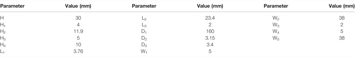
TABLE 1. Dimensions of the proposed antenna.
Comparison of Monopoles With Different Sector Number N
The sector number N of the monopole plays an important role in the impedance matching and gain variation, and it should be carefully determined. For clarity, the simulations of monopoles with sector number N = 2, 3, 4 are conducted here. The geometries of the monopoles with N = 2, 3, 4 are given in Figure 2A, Figure 2B and Figure 2C respectively. It should be mentioned that the metal loops are removed and each sector has the same parameters with those in Table 1 in all the monopole models. The simulated reflection coefficient for different sector number N is plotted in Figure 3A. As observed, the impedance matching is improved over almost the whole frequency band as N increased from 2 to 4. Furthermore, it is seen from Figures 3B–D that the current is more evenly distributed on the radiator with the increase of the number of the sectors, resulting in gain variation improvement. For validation, Figure 3E illustrates the simulated gain variation for different sector number. As plotted, the gain variation is significantly reduced from 5 dBi to 1.8 dBi as N increased from 2 to 4. The omnidirectional-radiation performance is improved with the increasing number N of the sectors. Therefore, the sector number N is selected as 4 to obtain good impedance matching and small gain variation in this design.
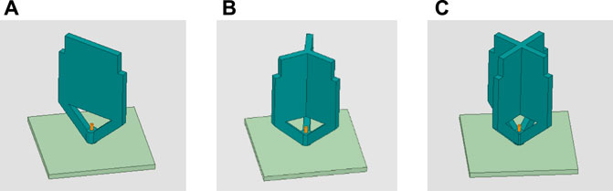
FIGURE 2. Monopoles with different sector number N: (A) N = 2, (B) N = 3, and (C) N = 4.
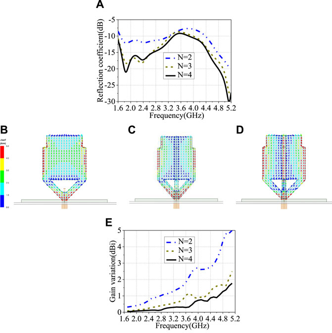
FIGURE 3. Simulated results of different monopoles: (A) reflection coefficient, current distribution at 5.1 GHz of monopoles with different sector number N (B) N = 2, (D) N = 3, and (D) N = 4, (E) gain variation.
Design Process
The evolutionary process of our antenna is demonstrated in Figure 4. Ant 1 is an original four-sector monopole antenna with a metal reflector. When metal loop 1 is added to Ant 1, Ant 2 is introduced. After employing metal loop 2 to Ant 2, our antenna, named Ant 3, is finally obtained.
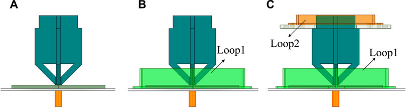
FIGURE 4. Evolution steps of the proposed antenna: (A) Ant1, (B) Ant2, (C) Ant3.
To further understand the design process of our antenna, the input impedances and the reflection coefficients of Ant 1–3 are illustrated in Figure 5 and Figure 6, respectively. For Ant 1, the resistance is near 50 Ω and the reactance is near 0 Ω at the frequencies of around 1.85 and 5.13 GHz, resulting in two resonant modes at the two frequencies, and good impedance matching are achieved at the lower and higher frequency bands. However, a low resistance of around 30 Ω and a high reactance of around 25 Ω are observed at 3.6 GHz, leading to impedance mismatch at the center frequency band. As metal loop 1 is added in Ant 2, the lower-frequency resonance almost remains the same but the high-frequency resonance removes to 3.7 GHz. This results in good impedance matching at the lower and center frequency bands. Meanwhile, Ant 2 has small resistance and large reactance at around 5 GHz, which causes impedance mismatch at the higher band. When the dual loops are added in Ant 3, stable resistance of around 50 Ω and reactance of around 0 Ω are realized over the whole frequency band, and four resonant modes at 1.83, 2.84, 4.13 and 4.90 GHz are successfully generated. This results is excellent impedance matching at 1.7–5.1 GHz (RL < −17 dB). These results prove the effectiveness of the metal loops on the impedance matching for the proposed antenna.
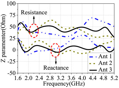
FIGURE 5. Input impedances of Ant 1, Ant 2, and Ant 3.
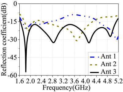
FIGURE 6. Reflection coefficients of Ant 1, Ant 2, and Ant 3.
It should be mentioned that loop 2 is also used to enhance the omnidirectional radiation performance. Figure 7A illustrates the current distribution on the proposed antenna at 5.1 GHz. As observed, strong current distributes on the monopole and metal loop 2. In this way, both the monopole and loop 2 generate radiation. Therefore, the ripples of the radiation pattern in the xy-plane can be reduced due to the simultaneous radiation of the monopole and loop 2. Figure 7B plots the simulated gain variation for Ant 1–3. It is plotted that the gain variation remains almost the same for Ant 1 and Ant 2 over the operating band, but it drops to 1.3 dBi at 5.1 GHz in the attendance of loop 2 for Ant 3.

FIGURE 7. (A) Current distribution of proposed antenna at 5.1 GHz, and (B) gain variations of Ant 1, Ant 2, and Ant 3.
According to the description above, the design process of our antenna is provided below.
Step 1; design a four-sector monopole antenna with a FR4 substrate and a metal reflector to obtain omnidirectional radiation with small gain variation and good impedance matching at the lower and higher frequency bands.
Step 2; insert metal loop 1 upon the reflector to enhance the impedance matching at the center band.
Step 3; introduce metal loop 2 around the top of the monopole to achieve excellent impedance matching and improve the omnidirectional radiation performance within an ultrawide frequency band of 1.7–5.1 GHz.
Measured Results and Discussion
A prototype of our antenna based on the parameters in Table 1 is fabricated and measured. Its photograph and measured reflection coefficient are plotted in Figure 8A and Figure 8B respectively. As observed, the measured RL is more than 15 dB over an ultrawide bandwidth of 103% (1.63–5.10 GHz).
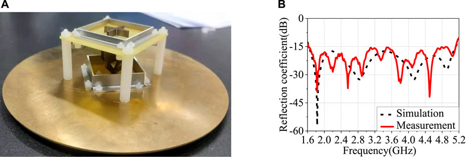
FIGURE 8. (A) Photograph and (B) measured reflection coefficients of the proposed antenna.
The measured radiation patterns at the frequencies of 1.7, 3.5 and 5 GHz are depicted in Figure 9A, Figure 9B and Figure 9C respectively. The elevation plane (E-plane) and the azimuth plane (H-plane) are defined as x-z plane and x-y plane respectively. As plotted, the measured patterns match the simulations well. The antenna achieves excellent omnidirectional radiation patterns in the H-plane and bi-directional radiation patterns in the E-plane. The measured gain and gain variation in the H-plane are shown in Figure 10. The measured gain is 3.25 ± 1.35 dBi and the gain variation is lower than 0.9 dBi over the operating band. The measured radiation efficiency is better than 76% over the operating band, as plotted in Figure 11.
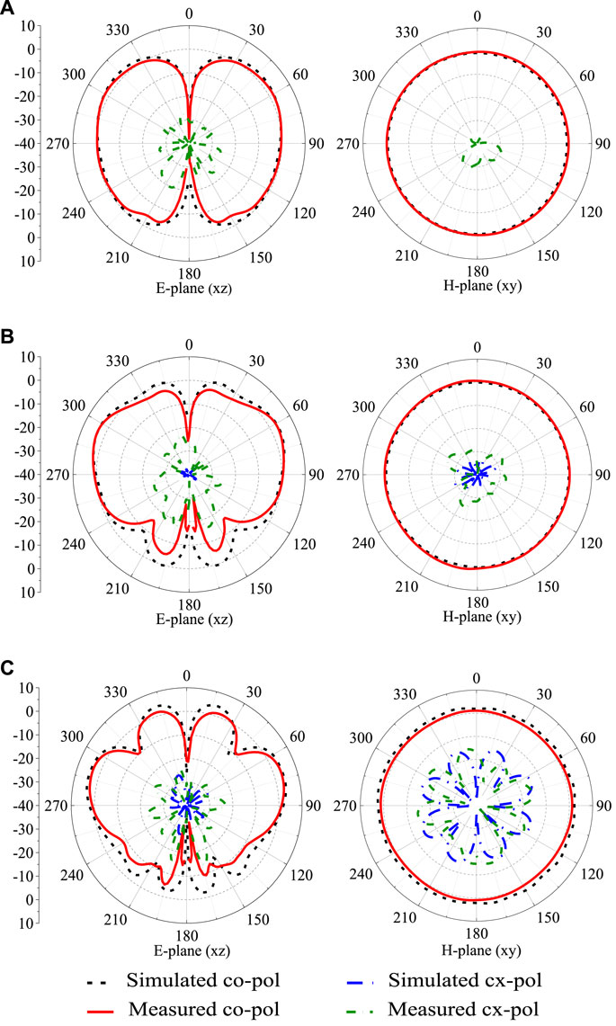
FIGURE 9. Measured radiation patterns of the proposed antenna for E-plane (x-z plane) and H-plane (x-y plane) at (A) 1.7 GHz, (B) 3.5 GHz, and (C) 5 GHz.
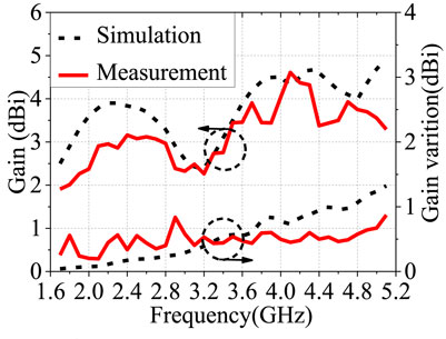
FIGURE 10. Measured gain and gain variation of the proposed antenna.
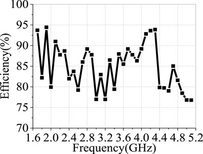
FIGURE 11. Measured efficiency of the proposed antenna.
A comparison of our antenna with other counterparts in the open literature is provided in Table 2. Compared with the wideband patch antenna in [6], slot antenna in [8], and monopole antennas in [14–16], our antenna has advantages of better impedance matching, much lower gain variation over a wider frequency band with moderate gain, efficiency and size. Compared with the UBW loop antenna in [9], the proposed antenna achieves much better impedance matching and much lower gain variation. The good performances make this design promisingly for indoor base station applications.
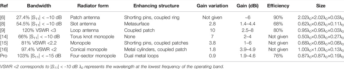
TABLE 2. Performance comparison of vertically polarized antennas.
Conclusion
An ultra-wideband vertically polarized omnidirectional antenna has been designed. Four resonant modes are generated by combining dual metal loops around a four-sector monopole to introduce excellent impedance matching. In addition, excellent omnidirectional radiation pattern with very small ripple in the azimuth plane is obtained over the ultrawide bandwidth. These performances enable the proposed antenna to apply in 2G/3G/4G/5G indoor communications.
Data Availability Statement
The raw data supporting the conclusion of this article will be made available by the authors, without undue reservation.
Author Contributions
JP, LY, and XS designed the structure and fabricated the sample. JP and DF performed the experiments. The final manuscript was written by JP and XS. All authors contributed to the manuscript.
Funding
This work was supported in part by the Technical Support Special Project of State Administration for Market Regulation (Grant 2019YJ031), National Natural Science Foundation of China (Grant No. 62071130), Guangdong Quality Improvement and Development Fund (Grant No.2021ZJ04).
Conflict of Interest
The authors declare that the research was conducted in the absence of any commercial or financial relationships that could be construed as a potential conflict of interest.
Publisher’s Note
All claims expressed in this article are solely those of the authors and do not necessarily represent those of their affiliated organizations, or those of the publisher, the editors and the reviewers. Any product that may be evaluated in this article, or claim that may be made by its manufacturer, is not guaranteed or endorsed by the publisher.
References
1. Lau KL, Luk KM. A Wide-Band Monopolar Wire-Patch Antenna for Indoor Base Station Applications. Antennas Wirel Propag Lett (2005) 4:155–7. doi:10.1109/LAWP.2005.847432
2. Ashwini KA, Seongjin K, Sungik P, Donghoon K, Rehab SH, Kyeongjun K, et al. Shark-Fin Antenna for Railway Communications in LTE-R, LTE, and Lower 5G Frequency Bands. Prog Electromagnetics Res (2020) 167:83–94. doi:10.2528/PIER20040201
3.Miit. Ministry of Industry and Information Technology of China. [Online] (2019). Available from: http://www.srrc.org.cn/article23792.aspx (Accessed March 12 2008).
4. Yu Y, Xiong J, Wang R. A Wideband Omnidirectional Antenna Array with Low Gain Variation. Antennas Wirel Propag Lett (2016) 15:386–9. doi:10.1109/LAWP.2015.2446757
5. Al-Zoubi A, Yang F, Kishk A. A Broadband center-fed Circular Patch-Ring Antenna with a Monopole like Radiation Pattern. IEEE Trans Antennas Propagat (2009) 57(3):789–92. doi:10.1109/TAP.2008.2011406
6. Juhua Liu J, Shaoyong Zheng S, Yuanxin Li Y, Yunliang Long Y. Broadband Monopolar Microstrip Patch Antenna with Shorting Vias and Coupled Ring. Antennas Wirel Propag Lett (2014) 13:39–42. doi:10.1109/LAWP.2013.2295686
7. Li Y, Zhang Z, Feng Z, Iskander MF. Design of Omnidirectional Dual-Polarized Antenna in Slender and Low-Profile Column. IEEE Trans Antennas Propagat (2014) 62(4):2323–6. doi:10.1109/TAP.2014.2303817
8. Xu Y, Wen S, Dong Y. Vertically Polarized Loop-Fed Slot Antenna with Top-Loading Metasurface for Omnidirectional LTE Base Station Application. Antennas Wirel Propag Lett (2021) 20(12):2397–401. doi:10.1109/LAWP.2021.3113179
9. Behdad N, Li M, Yusuf Y. A Very Low-Profile, Omnidirectional, Ultrawideband Antenna. Antennas Wirel Propag Lett (2013) 12:280–3. doi:10.1109/LAWP.2013.2248693
10. Wen S, Xu Y, Dong Y. Low-profile Wideband Omnidirectional Antenna for 4G/5G Indoor Base Station Application Based on Multiple Resonances. Antennas Wirel Propag Lett (2021) 20(4):488–92. doi:10.1109/LAWP.2021.3054682
11. Li H, Li Y. Mode Compression Method for Wideband Dipole Antenna by Dual-point Capacitive Loadings. IEEE Trans Antennas Propagat (2020) 68(8):6424–8. doi:10.1109/tap.2020.2972642
12. Rahim T, Xu J. An Extremely Wideband Radome-Enclosed Cylindrical Dipole Antenna for Wireless Communication. Turk J Elec Eng Comp Sci (2017) 25:1404–11. doi:10.3906/elk-1602-247
13. Baudha S, Vishwakarma DK. A Compact Broadband Printed Monopole Antenna with U-Shaped Slit and Rectangular Parasitic Patches for Multiple Applications. Int J Microw Wireless Technol (2016) 8(8):1231–5. doi:10.1017/S1759078715000768
14. Wu J, Yang S, Chen Y, Qu S, Nie Z. A Low Profile Dual-Polarized Wideband Omnidirectional Antenna Based on AMC Reflector. IEEE Trans Antennas Propagat (2017) 65(1):368–74. doi:10.1109/TAP.2016.2631147
15. Wang J, Zhao L, Hao Z-C, Jin J-M. A Wideband Dual-Polarized Omnidirectional Antenna for Base Station/WLAN. IEEE Trans Antennas Propagat (2018) 66(1):81–7. doi:10.1109/TAP.2017.2772322
16. Kumar SV, Harish AR. Trefoil Torus Knot Monopole Antenna. Antennas Wirel Propag Lett (2016) 15:464–7. doi:10.1109/LAWP.2015.2453198
17. Wen S, Dong Y. A Low-Profile Wideband Antenna with Monopolelike Radiation Characteristics for 4G/5G Indoor Micro Base Station Application. Antennas Wirel Propag Lett (2020) 19(12):2305–9. doi:10.1109/LAWP.2020.3030968
Keywords: ultra-wideband antenna, omnidirectional antenna, vertically polarized antenna, monopole antenna, dual metal loops
Citation: Peng JD, Fu DQ, Ye LH and Shi X (2022) Ultra-Wideband Vertically Polarized Omnidirectional Antenna With Dual Metal Loops. Front. Phys. 10:915919. doi: 10.3389/fphy.2022.915919
Received: 08 April 2022; Accepted: 08 June 2022;
Published: 15 July 2022.
Edited by:
Yuancheng Fan, Northwestern Polytechnical University, ChinaCopyright © 2022 Peng, Fu, Ye and Shi. This is an open-access article distributed under the terms of the Creative Commons Attribution License (CC BY). The use, distribution or reproduction in other forums is permitted, provided the original author(s) and the copyright owner(s) are credited and that the original publication in this journal is cited, in accordance with accepted academic practice. No use, distribution or reproduction is permitted which does not comply with these terms.
*Correspondence: Xinrong Shi, c3hyZnJlZW1hbkAxMjYuY29t