 Rashid Mahmood1
 Imran Siddique2*
 Ilyas Khan3
 Mohamed Badran4
 Sadok Mehrez5,6
 Afraz Hussain Majeed1
 Sehrish Naaz1
- 1Department of Mathematics, Air University, Islamabad, Pakistan
- 2Department of Mathematics, University of Management and Technology, Lahore, Pakistan
- 3Department of Mathematics, College of Science Al-Zulfi, Majmaah University, Al-Majma’ah, Saudi Arabia
- 4Department of Mechanical Engineering, Faculty of Engineering & Technology, Future University in Egypt, New Cairo, Egypt
- 5Department of Mechanical Engineering, College of Engineering at Al Kharj, Prince Sattam Bin Abdulaziz University, Al-Kharj, Saudi Arabia
- 6Department of Mechanical Engineering, University of Tunis El Manar, Tunis, Tunisia
This manuscript explores the flow features of the Modified Cross Model in a channel with symmetric trapezoidal cavities in the presence of a circular obstacle. The non-dimensional governing equations and model for different parameters are evaluated via a Galerkin Finite Element Method The system of non-linear algebraic equations is computed by adopting the Newton method. A space involving the quadratic polynomials (
1 Introduction
Over the last few decades, the interaction of the fluid with solid structures has attracted enormous interest because of its widespread implications in heat exchanger tubes, cooling systems for nuclear power plants, transmission cables, bridges, and high-rise buildings. Scientists are quite interested in learning more about these procedural applications because they are used to mount the lift and to reduce drag. Originally, viscous flow around obstacles was the only topic that was addressed, but non-Newtonian fluids have since received a lot of attention as a result of technological advances across the industrial frontiers. The rheological pattern of such fluids is used to classify them. According to fluid researchers, the non-Newtonian fluids models defy Newton’s viscosity law and represent a non-linear relationship between deformation rate and shear stress. [1] addressed the flow features of non-linear fluid models through a circular pipe. They also addressed the analytical solutions of power law fluids with analogous rheology, as well as apparent logical tendencies in the relationship between the respective flow rates as a function of the applied pressure field. [2] examined the characteristics of shear-thinning fluid flow for the reduction of drag forces. Even in the nonappearance of specific rheological measurements, comparisons of fluid-flow data from entirely independent laboratories can be made. [3] considered a material analysis of fluidic transportation in a channel-driven cavity. In addition, they analyzed the pressure stagnation point that appeared at the upper edge of the cavity. [4, 5] have examined the influence of fluid forces of non-linear fluid flow in a channel with an open square cavity. Furthermore, they have deduced the pressure is nonlinear near the obstacle, and then becomes linear at the downstream regime. [6] numerically explored the characteristics of the thermal flow of Cross model fluid in a channel. Also, they have analyzed the fluid forces that are proportional to body forces. [7] have examined the influence of conjugate heat transfer of power-law fluid inside the open cavity in the presence of an elastic baffle. Moreover, they have found a fluttering phenomenon for higher Reynolds numbers with lower values of power-law index (
The power-law model is the most common type of generalized Newtonian fluids which describes the pseudo-plastic and dilatant behaviors of several fluids. In spite of so many processes and applications, there are some limitations to the power-law fluid model and described only for a very limited shear rate range, also known as the power-law region. The Cross model, which is a wider and very important subclass of generalized Newtonian fluid, was presented to overcome all limitations of rheological models that are stated above and is able to illustrate the flow of fluids at every region for very high and very low shear rates regions and also at power law regions. [8] numerically simulated the 2D, laminar thermal flow in an annulus region by using finite volume technique. Also, they have shown the thermal conductivity ratio enhance as the increment in Rayleigh number. [9] studied the enhancement of MHD thermal flow by hybrid nanofluid in a novel configuration. They also examined the effects of physical controlling parameters of thermal flow characteristics. [10] numerically investigated the thermal flow enhancement of MHD nanofluid in a channel with a grooved trapezoidal cavity in the presence of an obstacle. In addition, they analyzed how the forced convection is dominant due to the increase in Hartmann number. [11] have investigated the characteristics of MHD thermal flow in a cavity by incorporating Galerkin finite element scheme. Moreover, the average Nusselt number has an increasing trend at both the right and bottom walls of the tank. [12] investigated the characteristics of thermal flow based on Peclet number in a square cavity in the presence of different boundary conditions. The simulation was done using the penalty-based FEM technique. [13] analyzed the flow features of the inclined magnetic field in a permeable cavity with thermal boundary conditions. Furthermore, they have examined the average Nusselt number’s decreasing trend by an increase in micropolar parameter and Hartmann number.[14] have presented the influence of MHD thermal flow in a trapezoidal cavity with a micropolar fluid in the presence of a uniformly heated bottom wall. Moreover, they have introduced the increasing trend in micropolar parameter, showing the isotherm contours are broken due to a decline in the thermal boundary layer. [15] have numerically investigated Darcy–Forchheimer nanomaterials flow over a cylinder in the appearance of thermal radiation effects. In addition, they have analyzed how the energy flux is greater in magnitude due to concentration gradient and density spectrum. [16] numerically investigated the enhancement in thermal flow by Alumina nanoparticles filled inside a cavity with various shapes of obstacles. Also, they have analyzed the multiple rotating cells that appear inside the cavity due to multiple obstacles. [17] analyzed the influence of fluid forces in a channel with triangular ribs. In addition, they have performed simulations by using the finite element technique.
The main focus of the present investigation is to explore the characteristics of a more generalized fluid model. The Cross model is given by the empirical equation that can be used to fit non-Newtonian data. This model represents the pseudoplastic flow including viscosities at zero and at infinite shear rates and no yield stress. The current study is organized as follows: mathematical formulation and numerical procedure are mentioned in section 2 and 3 while section 4 defines the results and discussion in detail. The study is concluded in section 5.
2 Mathematical Formulation
Let us consider a channel with the symmetric trapezoidal cavity of laminar incompressible modified cross model fluid flow around the circular cylinder with parabolic velocity at the inlet.
The coordinates of the figure are shown in Figure 1. For the generalized Newtonian fluid, the shear dependent dynamic viscosity is
Where
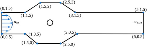
FIGURE 1. Schematic diagram of the domain.
Where
The governing system of Equations [5] for the given problem is as follows
The boundary conditions are set as follows:
At inlet
At outlet
All other walls of the channel as well as of the cavity are subject to zero no-slip conditions.
3 Numerical Procedure and Grid Convergence
Due to the non-linearity of the governing equations as well as of viscosity model fitted through Modified Cross Model, the analytical solution is not possible, so we employed numerical arrangement Finite Element Method (FEM) to compute the approximate solutions [18–24]. The underlying discrete non-linear equations have been solved by Newton method and the linearized inner system are solved with a direct solver PARDISO. The computational hybrid grid is shown in Figure 2A.
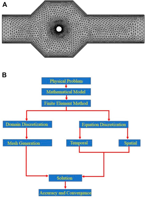
FIGURE 2. (A) Computational grid at coarse level. (B) Flow diagram of finite element method.
A grid independence study has been accomplished for the
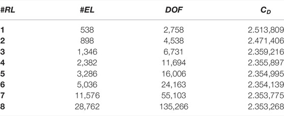
TABLE 1. Grid convergence study for drag coefficient
4 Results and Discussions
Figures 3–5 reveal the velocity profile, streamline plots, and pressure field in the domain for various values of the parameter m. The maximum velocity occurs when the flow is bifurcated around the cylinder, but with a different magnitude as depicted in Figure 4. According to the velocity profile, it can be said that, because of the recirculation, velocity in the cavities have negative values.
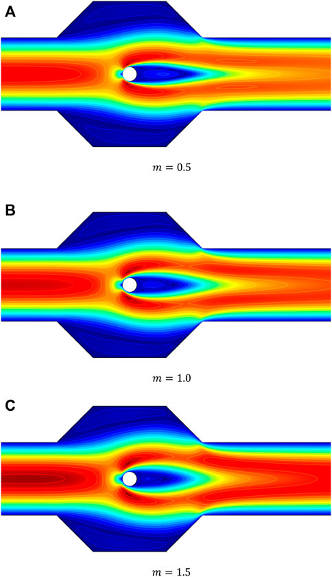
FIGURE 3. Effects on velocity for different values of
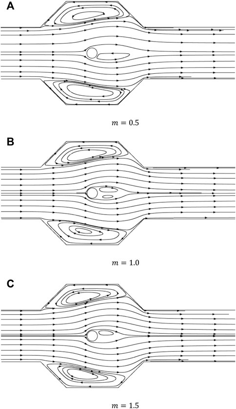
FIGURE 4. Effects on streamline for different values of
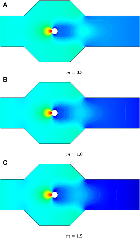
FIGURE 5. Effects on pressure for different values of
The size of vortex for the case of Newtonian fluid
In Figure 6 we present the line graphs at various locations to see the domain independence and impacts of parameters on the flow characteristics. The cutline of the velocity placed at
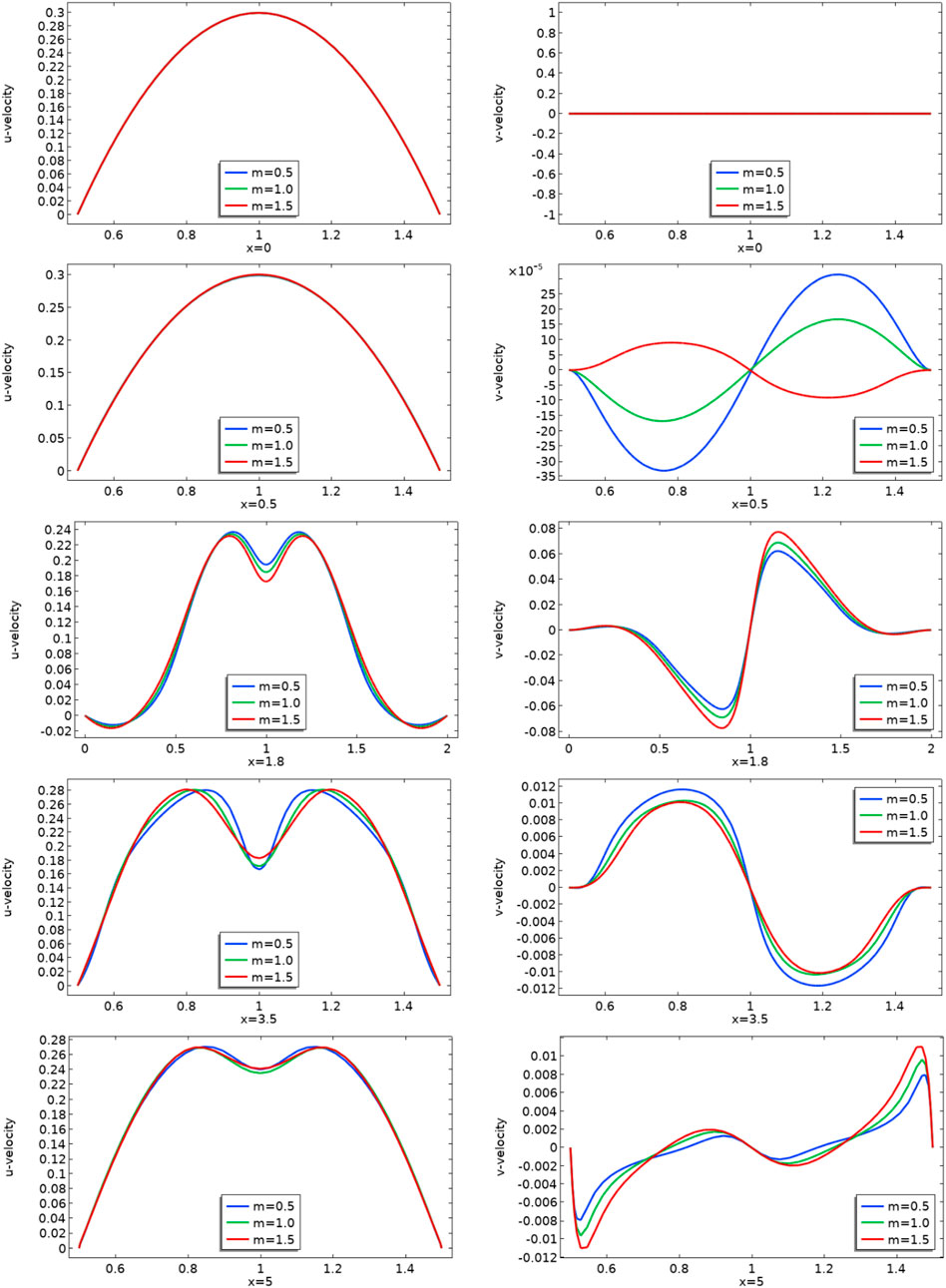
FIGURE 6. u and v velocities line profiles for various values of
Line integration over the boundary of obstacle

TABLE 2. Impact on drag and lift coefficients for
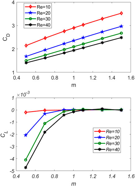
FIGURE 7. Drag and lift coefficients against
5 Conclusion
In this work, finite element-based simulations have been performed to numerically investigate the flow features of Modified Cross Model (MCM) in a trapezoidal cavity associated with a channel in the presence of an obstacle. A highly refined grid is chosen for accurate solutions. The effects of model parameters as well as of Reynolds number have been analyzed. The drag and lift coefficients are also computed for a wide range of involved parameters. The conclusions drawn from this study can be summarized as follows.
1) As
2) The drag coefficient (
3) For all values of
4) For the case of
Data Availability Statement
The raw data supporting the conclusions of this article will be made available by the authors, without undue reservation.
Author Contributions
Conceptualization; AM, IS, and RM. Methodology; IS, IK and MB, Funding acquisition; IK, MB and SM. Investigation; SM. Writing—original draft preparation; SN and AM. Writing—review and editing; IS, RM and MB. Supervision; IS. All authors have read and agreed to the published version of the manuscript.
Conflict of Interest
The authors declare that the research was conducted in the absence of any commercial or financial relationships that could be construed as a potential conflict of interest.
Publisher’s Note
All claims expressed in this article are solely those of the authors and do not necessarily represent those of their affiliated organizations, or those of the publisher, the editors and the reviewers. Any product that may be evaluated in this article, or claim that may be made by its manufacturer, is not guaranteed or endorsed by the publisher.
References
1. Sochi T. Analytical Solutions for the Flow of Carreau and Cross Fluids in Circular Pipes and Thin Slits. Rheol Acta (2015) 54(8):745–56. doi:10.1007/s00397-015-0863-x
2. Escudier MP, Gouldson IW, Pereira AS, Pinho FT, Poole RJ. On the Reproducibility of the Rheology of Shear-Thinning Liquids. J Non-Newtonian Fluid Mech (2001) 97(2-3):99–124. doi:10.1016/s0377-0257(00)00178-6
3. Mahmood R, Bilal S, Majeed AH, Khan I, Sherif E-SM. A Comparative Analysis of Flow Features of Newtonian and Power Law Material: A New Configuration. J Mater Res Technol (2019).
4. Mahmood R, Bilal S, Majeed AH, Khan I, Nisar KS. CFD Analysis for Characterization of Non-linear Power Law Material in a Channel Driven Cavity with a Square cylinder by Measuring Variation in Drag and Lift Forces. J Mater Res Technol (2020) 9:3838–46. doi:10.1016/j.jmrt.2020.02.010
5. Mahmood R, Bilal S, Majeed AH, Khan I, Nisar KS. Assessment of Pseudo-plastic and Dilatant Materials Flow in Channel Driven Cavity: Application of Metallurgical Processes. J Mater Res Technology (2020) 9:3829–37. doi:10.1016/j.jmrt.2020.02.009
6. Majeed AH, Mahmood R, Abbasi WS, Usman K. Numerical Computation of MHD Thermal Flow of Cross Model over an Elliptic Cylinder: Reduction of Forces via Thickness Ratio. Math Probl Eng (2021) 2021:1–13. doi:10.1155/2021/2550440
7. Yaseen DT, Ismael MA. Analysis of Power Law Fluid-Structure Interaction in an Open Trapezoidal Cavity. Int J Mech Sci (2020) 174:105481. doi:10.1016/j.ijmecsci.2020.105481
8. Al-Kouz W, Alshare A, Alkhalidi A, Kiwan S. Two-dimensional Analysis of Low-Pressure Flows in the Annulus Region between Two Concentric Cylinders. Springer (2016) 5:1–22. doi:10.1186/s40064-016-2140-6
9. Abu-Libdeh N, Redouane F, Aissa A, Mebarek-Oudina F, Almuhtady A, Jamshed W. Hydrothermal and Entropy Investigation of Ag/MgO/H2O Hybrid Nanofluid Natural Convection in a Novel Shape of Porous Cavity. Applied Sciences (2021) 11:1722. doi:10.3390/app11041722
10. A K, -Farhany , Alomari MA, Al-Saadi A, Chamkha A, Öztop HF. lMHD Mixed Convection of a Cu–Water Nanofluid Flow through a Channel with an Open Trapezoidal Cavity and an Elliptical Obstacle. Heat Transfer (2022) 51(2):1691–710. doi:10.1002/htj.22370
11. Nazeer M, Ali N, Javed T, Nazir MW. Numerical Analysis of the Full MHD Model with the Galerkin Finite-Element Method. Eur Phys J Plus (2019) 134:204. doi:10.1140/epjp/i2019-12562-9
12. Nazeer M, Ali N, Javed T, Razzaq M. Finite Element Simulations for Energy Transfer in a Lid-Driven Porous Square Container Filled with Micropolar Fluid: Impact of thermal Boundary Conditions and Peclet Number. Int J Hydrogen Energ (2019) 44:7656–66. doi:10.1016/j.ijhydene.2019.01.236
13. Ali N, Nazeer M, Javed T. Finite Element Simulations of Free Convection Flow inside a Porous Inclined Cavity Filled with Micropolar Fluid. J Porous Media (2021) 24:57–75. doi:10.1615/jpormedia.2020024977
14. Nazeer M, Ali N, Javed T, Asghar Z. Natural Convection through Spherical Particles of Micropolar Fluid Enclosed in Trapezoidal Porous Container: Impact of Magnetic Field and Heated Bottom wall. Eur Phys J Plus (2018). 133:1–10. doi:10.1140/epjp/i2018-12217-5
15. Ali L, Wang Y, Ali B, Liu X, Din A, Mdallal Q, et al. The Function of Nanoparticle’s Diameter and Darcy-Forchheimer Flow over a cylinder with Effect of Magnetic Field and thermal Radiation. Case Stud Therm Eng (2021) 28:101392. doi:10.1016/j.csite.2021.101392
16. Ganesh NV, Javed S, Al-Mdallal QM, Kalaivanan R, Chamkha AJ. Numerical Study of Heat Generating γ AlO– HO Nanofluid inside a Square Cavity with Multiple Obstacles of Different Shapes. Heliyon (2020) 6:e05752. doi:10.1016/j.heliyon.2020.e05752
17. Rehman KU, Al-Mdallal QM, Tlili I, Malik MY. Impact of Heated Triangular Ribs on Hydrodynamic Forces in a Rectangular Domain with Heated Elliptic cylinder: Finite Element Analysis. Int Commun Heat Mass Transfer (2020) 112:104501. doi:10.1016/j.icheatmasstransfer.2020.104501
18. Bilal S, Mahmood R, Majeed AH, Khan I, Nisar KS. Finite Element Method Visualization about Heat Transfer Analysis of Newtonian Material in Triangular Cavity with Square cylinder. J Mater Res Technology (2020) 9(3):4904–18. doi:10.1016/j.jmrt.2020.03.010
19. Majeed AH, Jarad F, Mahmood R, Saddique I. Topological Characteristics of Obstacles and Nonlinear Rheological Fluid Flow in Presence of Insulated Fins: A Fluid Force Reduction Study. Math Probl Eng 2021:2021–15. doi:10.1155/2021/9199512
20. Ahmad H, Mahmood R, Hafeez MB, Hussain Majeed A, Askar S, Shahzad H. Thermal Visualization of Ostwald-De Waele Liquid in Wavy Trapezoidal Cavity: Effect of Undulation and Amplitude. Case Stud Therm Eng (101698) 29:2021. doi:10.1016/j.csite.2021.101698
21. Mahmood R, Majeed AH, Ain QU, Awrejcewicz J, Khan I, Shahzad H. Computational Analysis of Fluid Forces on an Obstacle in a Channel Driven Cavity: Viscoplastic Material Based Characteristics. Materials (2022) 15:529. doi:10.3390/ma15020529
22. Khan Y, Majeed AH, Shahzad H, Awan FJ, Iqbal K, Ajmal M, et al. Numerical Computations of Non-newtonian Fluid Flow in Hexagonal Cavity With a Square Obstacle: A Hybrid Mesh–Based Study. Front Phys (2022) 10:891163. doi:10.3389/fphy.2022.891163
23. Mahmood R, Jaradat MMM, Ali R, Saddique I, Majeed AH, Mehmood A. Finite Element Analysis of the Dynamics of Power-Law Fluid Around an Obstacle in a Channel. Math Probl Eng (2022) 2022:1. doi:10.1155/2022/3160951
24. Majeed AH, Mahmood R, Hamadneh NN, Siddique I, Khan I, Alshammari N, et al. Periodic Flow of Non-newtonian Fluid Over a Uniformly Heated Block With Thermal Plates: A Hybrid Mesh-Based Study. Front Phys (2022) 10:829085. doi:10.3389/fphy.2022.829085
Nomenclature
b Scale parameter
D Diameter of the obstacle
H Height of inlet
#EL ELNumber of Elements
# DOF Number of degrees of freedom
Keywords: modified cross model fluid, FEM computation, symmetric trapezoidal cavities, fluid forces, neumann conditions
Citation: Mahmood R, Siddique I, Khan I, Badran M, Mehrez S, Majeed AH and Naaz S (2022) Numerical Computation for Modified Cross Model Fluid Flow Around the Circular Cylinder with Symmetric Trapezoidal Cavities. Front. Phys. 10:912213. doi: 10.3389/fphy.2022.912213
Received: 04 April 2022; Accepted: 30 May 2022;
Published: 18 July 2022.
Edited by:
Kh S. Mekheimer, Al-Azhar University, EgyptReviewed by:
Mubbashar Nazeer, Government College University, PakistanQasem M. Al-Mdallal, United Arab Emirates University, United Arab Emirates
Copyright © 2022 Mahmood, Siddique, Khan, Badran, Mehrez, Majeed and Naaz. This is an open-access article distributed under the terms of the Creative Commons Attribution License (CC BY). The use, distribution or reproduction in other forums is permitted, provided the original author(s) and the copyright owner(s) are credited and that the original publication in this journal is cited, in accordance with accepted academic practice. No use, distribution or reproduction is permitted which does not comply with these terms.
*Correspondence: Imran Siddique, aW1yYW5zbXNyYXppQGdtYWlsLmNvbQ==