 Huagen Yang
 Kan Feng*
95% of researchers rate our articles as excellent or good
Learn more about the work of our research integrity team to safeguard the quality of each article we publish.
Find out more
ORIGINAL RESEARCH article
Front. Phys. , 18 May 2022
Sec. Physical Acoustics and Ultrasonics
Volume 10 - 2022 | https://doi.org/10.3389/fphy.2022.909318
This article is part of the Research Topic New Trends in Architectured Functional Materials View all 6 articles
As a new kind of elastic materials, elastic wave metasurface has great research significance in the field of elastic wave regulation. However, most of the researches on elastic wave metasurface are guided by traditional Generalized Snell’s Law (GSL), and the effect of higher order diffraction waves caused by structural periodicity is not considered. Under the action of higher order diffraction wave, the incident wave will produce more complex transmission phenomenon when passing through the metasurface, and the angle of transmission does not conform to GSL in some cases. In order to verify whether the modified GSL theory considering the higher-order diffraction term is still applicable to the regulation of solid elastic waves, this paper designs a helical metasurface based on the elastic wave theory of plate-beam structure, which is composed of helical lines of different lengths, and uses this structure to explain the complex transmission phenomenon of elastic wave metasurface. Finally, the asymmetric transmission, modal separation and waveguide of Lamb waves in thin plates are realized by combining the theory with structural design, which proves that the structure has great application potential in ultrasonic detection and other fields.
Elastic waves are a classical form of motion in engineering structures, and the mechanical vibrations of major equipment such as aerospace vehicles, underwater probes, and high-speed trains are essentially the superimposed effects of their internal elastic waves. With the depth of research, the regulation of elastic waves has gradually become the focus of attention, and the emergence of metasurface structures [1–3] in recent years is one of the means to effectively regulate elastic waves.
In 2011, Yu et al [4] introduced phase mutation at the interface through a periodic array of V-shaped antennas to reach the modulation of the phase of the incident light wave and further realize the anomalous reflection and transmission of the wave, and the reflection and transmission angles satisfy the so-called Generalized Snell’s Law (GSL). The proposed GSL shows that it is possible to introduce the phase mutation through a two-dimensional interface, and thus a series of anomalous acoustic phenomena such as negative refraction and acoustic focusing can be realized more easily and conveniently. In 2013, Li et al [5] extended GSL from optics to acoustics and designed a spatially folded metasurface to discretize the phase gradient to achieve anomalous reflection and acoustic focusing. Since then, a large number of studies have emerged on the use of metasurfaces to modulate the phase of acoustic waves. In 2014, Xie et al [6] pointed out that due to the periodicity of the metasurface structure, higher-order diffraction occurs when the incident wave is larger than a certain critical angle, and the transmission angle no longer satisfies the GSL, and the higher-order diffraction term needs to be introduced to correct the law. However, after related studies, it is shown that the corrected law still cannot explain all the anomalies well. In 2019, the correction theory was further supplemented by Fu et al [7], who pointed out that the higher-order diffraction waves in the metasurface exhibit alternating reflection and transmission, and the factor affecting whether the reflection or transmission occurs is the number of structural unit cells.
The study of acoustic wave metasurfaces has matured in the last decade. However, in the study of elastic wave metasurfaces, since elastic waves in solids have more degrees of freedom and more complicated wave equations, transverse waves and longitudinal waves, as well as various forms of waves formed by mutual coupling, are often accompanied by the mode conversion is obviously more complicated than the single longitudinal wave mode in air and liquid, which directly leads to the late start of research on elastic wave metasurfaces. It was not until 2016 that the concept of acoustic wave metasurfaces was further extended to elastic wave metasurfaces by Semperlotti et al [8], who designed a conical column metasurface structure. When a plate wave passes through this structure in a periodic arrangement, a weak local resonance effect occurs, which leads to mode conversion and thus to transmission manipulation of A0 waves. In 2017, Liu et al [9] realized a bending wave vibration source phantom by constructing a sawtooth type structure. In 2020, Yuan et al [10] ingeniously designed a “fishbone” type semi-active metasurface, which could regulate the phase of transmitted waves by rotating the nuts, and in 2021, Yaw et al [11] introduced a coded negative capacitance circuit in the metasurface to achieve active modulation of longitudinal waves. During this period, there are still some researches on the use of metasurfaces to modulate elastic waves [12–29], mainly including the ingenious design of structures and the exploration of application means, etc. However, no matter active or passive elastic wave metasurfaces, a large number of research works are limited to the ordinary first-order diffraction, and the mechanism of elastic wave diffraction for higher-order diffraction has not been systematically studied.
Therefore, to address the above issues, the following works are done in this paper: 1. A new helical type metasurface is designed independently, and it is verified by simulation that the Lamb wave still fits the modified GSL, but it does not fit perfectly due to the multimodal and dispersion characteristics of the Lamb wave and the limitation of the structure itself. 2. Based on the modification principle, the helical type elastic wave metasurface structure is used to design and realize the Lamb wave nearly full-angle asymmetric transmission phenomenon, the separation of antisymmetric and symmetric modes and the waveguide structure. While verifying the universality of the correction theory in the field of elastic waves, it also provides an aid for the application of guided waves in the fields of nondestructive testing and architectural acoustics, and a new way for the fine processing of Lamb waves.
If a phase gradient is introduced at the interface of two media through a metasurface, disrupting the original phase continuity at the interface, then the direction of the transmitted wave no longer satisfies Snell’s law, but will follow the GSL proposed by Yu et al in 2011, written in the following form [4]:
Where,
If the incident angle
Where
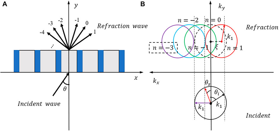
FIGURE 1. (A) high-order diffraction phenomenon of periodic structure; (B) interpretation of the angular correspondence between the incident and transmitted waves by means of wave vectors.
The physical meaning of the equation can be better illustrated by the wave vector diagram in Figure 1B. For each incident angle
Where
However, not all of the sound waves will be transmitted along their respective diffraction channels, and Fu treats a unit cell in the metasurface structure as a Fabry-Perot resonator, as shown in Figure 2. When the angle
where,
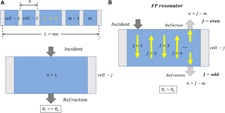
FIGURE 2. (A) When the incident angle is less than or equal to the critical angle, the incident wave is transmitted normally from the unit cell; (B) When the incident angle is greater than the critical angle, the unit cell can be regarded as a Fabry-Perot resonator.
In this paper, we design a helical metasurface for modulating Lamb waves, which consists of a series of helical curved beam cells, as shown in Figure 3, where

FIGURE 3. Helical metasurface structural parameters.
It is worth noting that the waves in the thin plate exist in the form of Lamb waves, while in the curved beam exist mainly in the form of bending waves, and there is a difference in the wave numbers between them. The wave numbers
In order to address the problem that a large number of elastic wave metasurfaces are still based on the GSL law which does not consider the higher order diffraction terms, this paper verifies the universality of the modified GSL theory by using the helical metasurface designed above.
Since the parity of the number of unit cells (actually, the number of equal parts of the
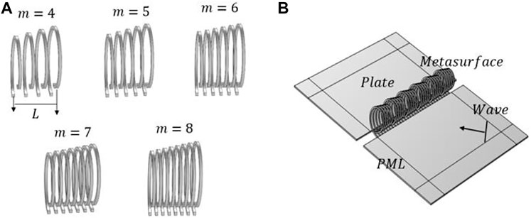
FIGURE 4. (A) Helical metasurface structures with different numbers of unit cells; (B) Schematic diagram of the overall structure.
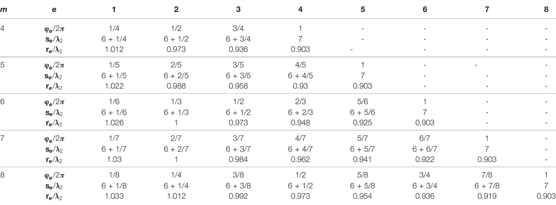
TABLE 1. Values of phase
In our study, the commercial simulation software COMSOL is used to numerically simulate the phenomenon of controlling the plate wave transmission through the metasurface structure. Both the thin plate and the metasurface are made of aluminum, the elastic modulus is 70GPa, the Poisson’s ratio is 0.33, and the density is 2700 kg/m^3, and the excitation is set to a line excitation with a common ultrasonic excitation frequency of 100 kHz and an amplitude size of 1 mm. The metasurface structure is periodically arranged in the middle of the plate, and the overall structure is shown in Figure 4B.
When the Lamb wave is incident at −30° (the angle of incidence is less than the critical angle 0°), according to the above theoretical analysis, the number of unit cells does not affect the transmission because no higher-order diffraction waves are generated at this time. The simulation results are exactly the same, as shown in Figure 5. Although there are some unexpected reflections at
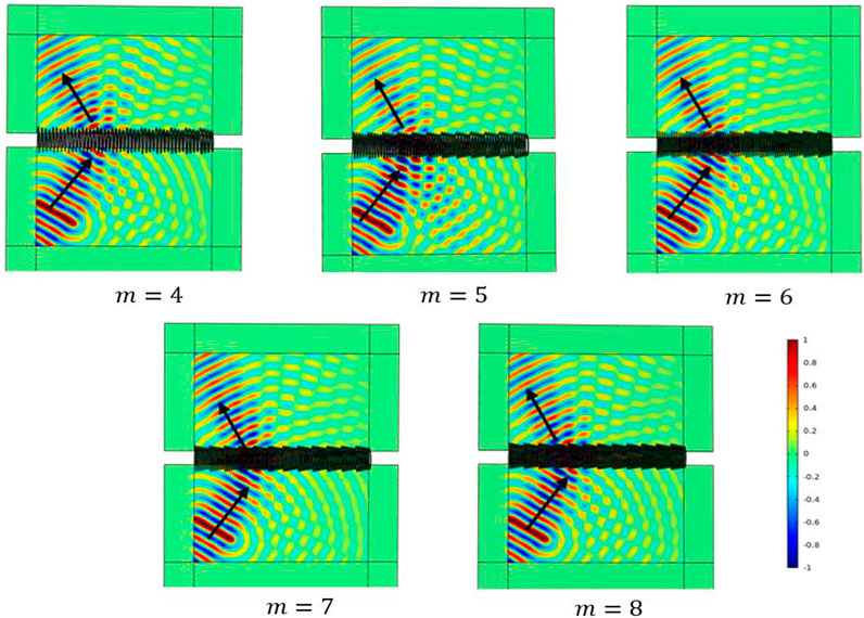
FIGURE 5. When the incident angle is -30°, the corresponding transmission wavefields of metasurfaces with different unit cell numbers.
When the wave is incident in the direction of 30° (the angle of incidence is greater than the critical angle of 0°), higher order diffraction phenomenon will be generated at this time, where the maximum diffraction level
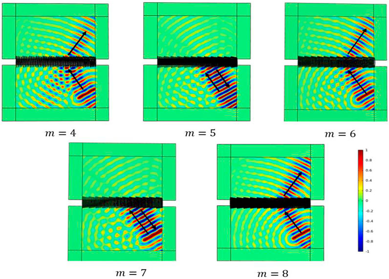
FIGURE 6. When the incident angle is 30°, the corresponding transmission wavefields of metasurfaces with different unit cell numbers.
From Eq. 4, it can be seen that, without changing the wavelength of the incident wave, only increasing the length
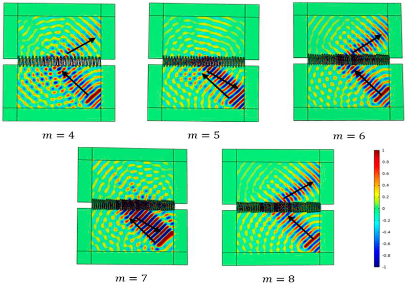
FIGURE 7. When
In conclusion, Lamb wave also conforms to the modified diffraction law to some extent, but the existence of multi-mode and dispersion in the guided wave, or the problem of the structure itself, lead to weak reflection and transmission energy in other diffraction channels.
According to the theory in the previous section, if set
When the incident angle is less than or equal to 0°, it conforms to the classical GSL. Substitute
Combining Eqs. 7, 8, it can be seen that when the two incident wave directions are symmetric about the vertical axis, the transmitted wave directions will also behave as axisymmetric, and the incident wave angle will always remain opposite in sign to the transmitted angle (except for 0°). This also indicates that it is theoretically possible to achieve nearly full-angle negative refraction except for the incident angle of 0°. Therefore, in this paper, the number of unit cells is set to
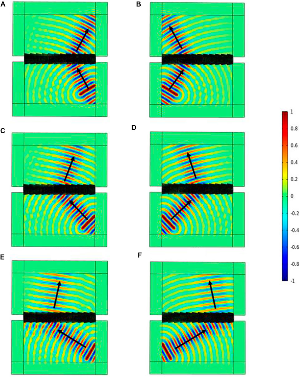
FIGURE 8. Wide-angle negative refraction phenomenon of the incident waves: (A) 30°; (B) -30°; (C) 45°; (D) -45°; (E) 60°; (F) -60°.
As an important acoustical phenomenon, asymmetric transmission enables unidirectional wave transmissibility, waves can propagate from one side to the other side of the interface, while they cannot transmit from the reverse direction, such phenomena have great potential for application. In the field of elastic waves, the asymmetric transmission of waves can also be realized by metasurface structures. Therefore, in this paper, an asymmetric transmission device is designed based on the theory of parity-related diffraction, which only allows the single-pass of waves and perfectly realizes the wide-angle asymmetric transmission of Lamb waves.
Setting
Therefore, the number of unit cells is set to
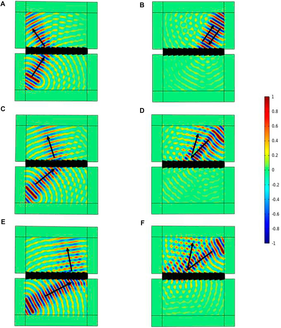
FIGURE 9. Wide-angle asymmetric transmission of incident waves: (A) lower left corner -30° (B) upper right corner 30°; (C) lower left corner -45° (D) upper right corner 45°; (E) lower left corner - 60°(F) 60° to the upper right corner.
When Lamb waves are used for structural damage monitoring, they often cause wave packet mixing because they have multiple modes, which further causes the damage signal to be difficult to identify and the problem of inaccurate damage imaging. How to separate the different modes of Lamb waves quickly and accurately is one of the important problems in the field of structural health monitoring that needs to be solved.
In this section, based on the difference of wave velocities between symmetric mode (S) and antisymmetric mode (A) of Lamb wave, a simple mode separator is constructed based on the parity-related diffraction theory, and the separation of A0 mode and S0 mode waves at an excitation frequency of 100 kHz is initially realized.
First, the aluminum plate dispersion curve was plotted, as shown in Figure 10. According to this figure, the wave velocities of A0 mode and S0 mode wave at the frequency thickness product of 100 kHz*1 mm are 951.9 m/s and 5373 m/s, respectively, in other words, the wavelength of S0 mode wave at this frequency is 5.6 times that of A0,
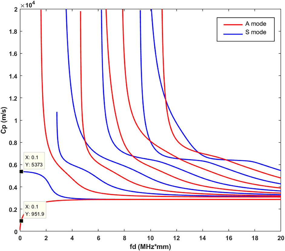
FIGURE 10. Dispersion curve of aluminum plate.
Second, according to the parity-related diffraction theory and Eq. 4, it is known that for the S0 mode,
The above equation shows that the transmission or reflection angle is equal to the incidence angle when the S0 mode wave at this frequency thickness product is incident in any direction. However, for the A0 mode wave, when it is incident vertically in the 0° direction, it satisfies the classical GSL Eq. 1, with a theoretical transmission angle of 65.4°. In order to illustrate the effect of mode separation when Lamb wave field is excited in three cases: 1. A0 mode (control group) 2. A0 and a few S0 modes 3. S0 and a few A0 modes, three excitations are selected in this section based on the principle that symmetric (S) and antisymmetric (A) modes are dominated by in-plane and off-plane displacements, respectively: (a) antisymmetric excitation about the xy plane (b) symmetric excitation (c) antisymmetric excitation about the xz plane, and the schematic diagram is shown in Figure 11.
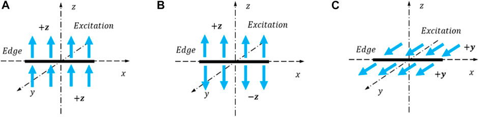
FIGURE 11. Three types of excitation: (A) Antisymmetric excitation about the xy plane; (B) symmetric excitation; (C) antisymmetric excitation about the xz plane.
Then the first excitation method (a) is chosen, the excitation frequency is selected as 100 kHz, the amplitude size is 1 mm so that the structure length of the single-cycle metasurface
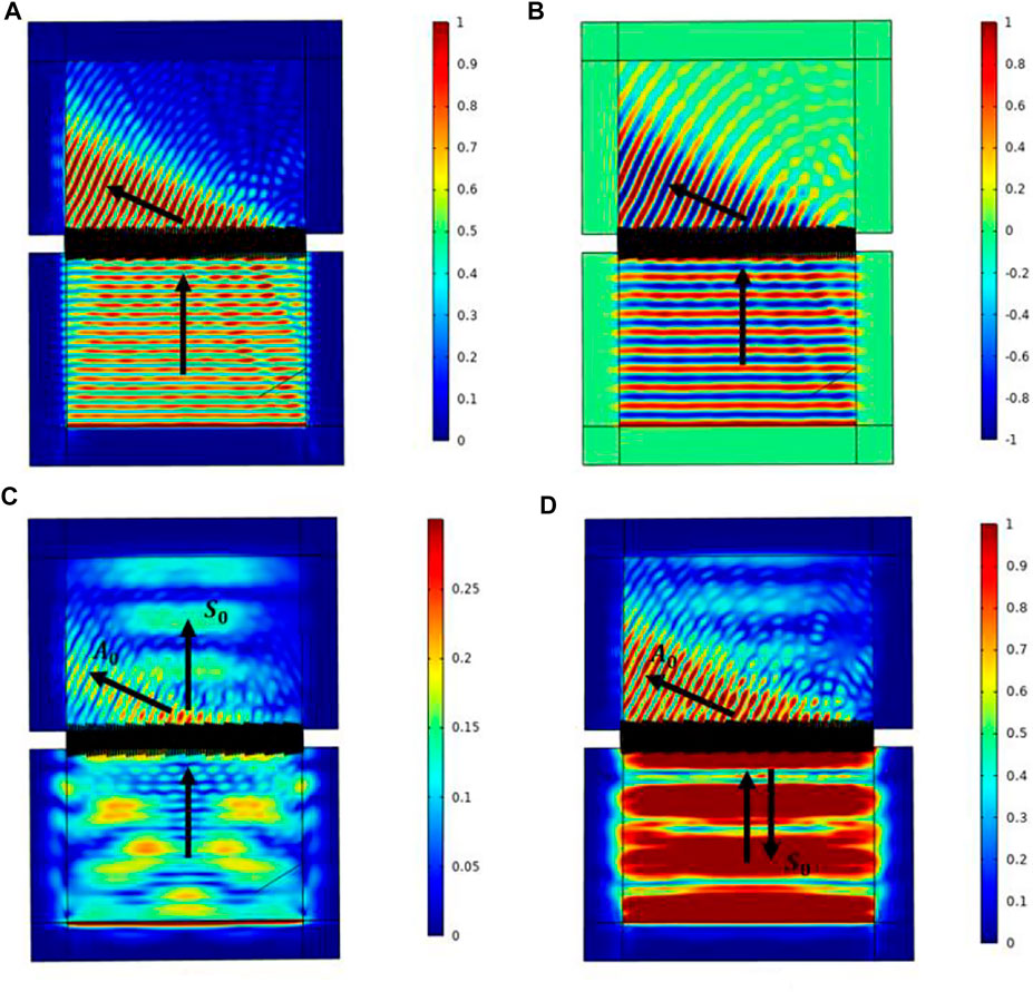
FIGURE 12. (A) Total displacement corresponding to the first excitation method (combined plot of displacements in three directions); (B) z-directional displacement (off-plane displacement); (C) total displacement corresponding to the second excitation method; (D) total displacement wavefield corresponding to the third excitation method.
Next, the second excitation method (b) is adopted, about z-directional symmetric excitation, which can excite part of the S0 mode wave. The theoretical analysis in this subsection shows that when the wave is incident at 0°, the A0 wave will transmit at 65.4°, while the S0 wave will maintain 0° transmission, and the two transmission directions are different, forming the beam separation phenomenon. The simulation results are shown in Figure 12C, and it can be found that the Lamb wave field in the figure achieves a mode separation phenomenon consistent with the theory, with the shorter wavelength being the A0 wave and the opposite being the S0, and the deflection angle is also consistent with the theoretical prediction.
Finally, the third excitation method is used, which can excite the S0 mode with mainly in-plane displacement (y-direction displacement). The rest of the settings remain unchanged, and only the number of unit cells
In conclusion, this section designs this metasurface structure as a simple mode separator based on the parity-related diffraction theory, combined with the difference in the wavelengths of Lamb wave A0 and S0 modes. Moreover, a reasonable size can be designed based on the above theory to realize the separation of multiple modal waves of Lamb waves in any direction according to the actual needs.
Similar to the case of S0 wave propagation in the previous section, it is known from Eq. 4 that when
First, set
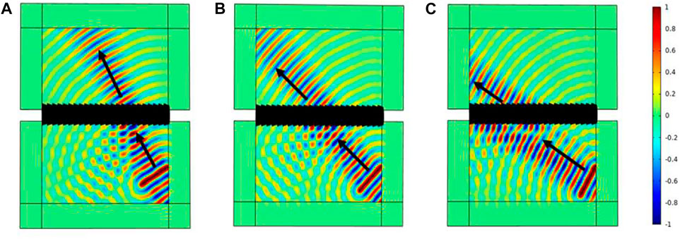
FIGURE 13. When the number of unit cells is m = 7, the wave field of the incident wave incident at different angles: (A) 30°; (B) 45°; (C) 60°.
Then set
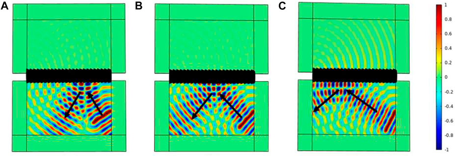
FIGURE 14. When the number of unit cells is m = 8, the wave field of the incident wave incident at different angles: (A) 30°; (B) 45°; (C) 60°.
Based on the above discussion, a waveguide structure is designed by using this total reflection phenomenon. The structure schematic is shown in Figure 15A, which consists of two layers of the metasurface, and the middle range is the waveguide area. A line excitation is applied on the small semicircular edge, and the excitation waves in different directions will reflect back and forth when they encounter the metasurface interface, thus achieving directional propagation. Considering the large amount of computation of the metasurface model, the width of the middle waveguide region is set to be narrower and the length is shorter. The final energy density diagram is shown in Figure 15B. Although the Lamb wave is essentially leak-free, the conduction region is too small, resulting in a difficult to distinguish the wave path when it propagates inside the waveguide. Even so, the idea of using the metasurface as a waveguide structure is still feasible. If the metasurface structure can be simplified and the waveguide region can be designed from straight lines to curves or loops, then better conduction and isolation effects of Lamb waves can be further achieved.
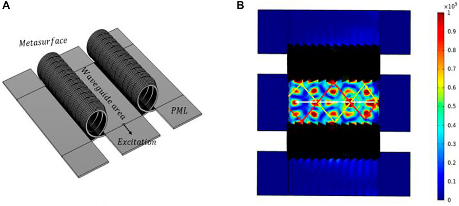
FIGURE 15. (A) Schematic diagram of metasurface waveguide structure; (B) energy density diagram of Lamb wave propagating in the waveguide region.
The modified GSL theory is introduced in this paper for the higher-order diffraction phenomena are often neglected in elastic wave metasurfaces. While verifying its correctness by using helical type metasurfaces, a series of acoustic phenomena and applications are also realized by this theory. The details are as follows:
By introducing the concept of phase gradient, and based on the plate - beam elastic wave propagation theory, a helical type metasurface is constructed. It is verified through this structure that the parity-related diffraction theory is still applicable in the field of elastic waves, and the theory is well conformed even when the number of diffraction levels is large.
According to the modified GSL theory, negative refraction and asymmetric transmission at nearly all angles (except 0°), separation of symmetric and anti-symmetric modes in Lamb waves, waveguide structure with directional transmission function are designed and realized. It is shown that the theory can not only improve the classical GSL law and play a better guiding significance, but also can realize some special functions in combination with the metasurface structure, which contains great potential for application in the fields of nondestructive testing and vibration noise control.
The original contributions presented in the study are included in the article/Supplementary Material, further inquiries can be directed to the corresponding author.
HY: Writing—original draft, Conceptualization, Methodology, Software, Data curation, Review of writing, editing, Visualization, Investigation. KF: structural scheme design and theoretical model analysis Funding acquisition, Formal analysis, Project administration, Review of writing, editing. RL: Supervision, Validation. JY: Visualization, Validation.
The project was supported by the National Natural Science Foundation of China (Grant no. 11702118), the Natural Science Foundation of Jiangsu Province (Grant no. BK20170520), and the Basic Research Program of Jiangsu Education Department (Grant no. 17KJB130005).
The authors declare that the research was conducted in the absence of any commercial or financial relationships that could be construed as a potential conflict of interest.
All claims expressed in this article are solely those of the authors and do not necessarily represent those of their affiliated organizations, or those of the publisher, the editors and the reviewers. Any product that may be evaluated in this article, or claim that may be made by its manufacturer, is not guaranteed or endorsed by the publisher.
We acknowledge the National Natural Science Foundation of China and the Natural Science Foundation of Jiangsu Province for their support.
1. Ma G, Yang M, Xiao S, Yang Z, Sheng P. Acoustic Metasurface with Hybrid Resonances. Nat Mater (2014) 13(9):873–8. doi:10.1038/nmat3994
2. Assouar B, Liang B, Wu Y, Li Y, Cheng J-C, Jing Y. Acoustic Metasurfaces. Nat Rev Mater (2018) 3(12):460–72. doi:10.1038/s41578-018-0061-4
3. Wang Z, Chu Y. Research Progress of Acoustic Metasurface in China. EPJ Appl Metamat (2019) 6:5. doi:10.1051/epjam/2019004
4. Yu N, Genevet P, Kats MA, Aieta F, Tetienne J-P, Capasso F, et al. Light Propagation with Phase Discontinuities: Generalized Laws of Reflection and Refraction. Science (2011) 334(6054):333–7. doi:10.1126/science.1210713
5. Li Y, Liang B, Gu ZM, Zou XY, Cheng JC. Reflected Wavefront Manipulation Based on Ultrathin Planar Acoustic Metasurfaces. Sci Rep (2013) 3(1):2546. doi:10.1038/srep02546
6. Xie Y, Wang W, Chen H, Konneker A, Popa BI, Cummer SA. Wavefront Modulation and Subwavelength Diffractive Acoustics with an Acoustic Metasurface. Nat Commun (2014) 5(1):5553. doi:10.1038/ncomms6553
7. Fu Y, Shen C, Cao Y, Gao L, Chen H, Chan CT, et al. Reversal of Transmission and Reflection Based on Acoustic Metagratings with Integer Parity Design. Nat Commun (2019) 10(1):2326. doi:10.1038/s41467-019-10377-9
8. Zhu H, Semperlotti F. Anomalous Refraction of Acoustic Guided Waves in Solids with Geometrically Tapered Metasurfaces. Phys Rev Lett (2016) 117(3):034302. doi:10.1103/PhysRevLett.117.034302
9. Liu Y, Liang Z, Liu F, Diba O, Lamb A, Li J. Source Illusion Devices for Flexural Lamb Waves Using Elastic Metasurfaces. Phys Rev Lett (2017) 119(3):034301. doi:10.1103/PhysRevLett.119.034301
10. Yuan S-M, Chen A-L, Wang Y-S. Switchable Multifunctional Fish-Bone Elastic Metasurface for Transmitted Plate Wave Modulation. J Sound Vibration (2020) 470:115168. doi:10.1016/j.jsv.2019.115168
11. Yaw Z, Zhou W, Chen Z, Lim CW. Stiffness Tuning of a Functional-Switchable Active Coding Elastic Metasurface. Int J Mech Sci (2021) 207:106654. doi:10.1016/j.ijmecsci.2021.106654
12. Zhang S, Shu S, Bian X. Tunability for Anomalous Refraction of Flexural Wave in a Magneto-Elastic Metasurface by Magnetic Field and Pre-Stress. Appl Phys Express (2022) 15:027003. doi:10.35848/1882-0786/ac4925
13. Li S, Xu J, Tang J. Tunable Modulation of Refracted Lamb Wave Front Facilitated by Adaptive Elastic Metasurfaces. Appl Phys Lett (2018) 112(2):021903. doi:10.1063/1.5011675
14. Qiu H, Li F. Manipulation of Shear Horizontal Guided Wave with Arbitrary Wave Fronts by Using Metasurfaces. J Phys D: Appl Phys (2020) 53(28):285301. doi:10.1088/1361-6463/ab850d
15. Ruan Y, Liang X, Hu C. Retroreflection of Flexural Wave by Using Elastic Metasurface. J Appl Phys (2020) 128(4):045116. doi:10.1063/5.0005928
16. Zheng M, Park CI, Liu X, Zhu R, Hu G, Kim YY. Non-Resonant Metasurface for Broadband Elastic Wave Mode Splitting. Appl Phys Lett (2020) 116(17):171903. doi:10.1063/5.0005408
17. Zhang J, Zhang X, Xu F, Ding X, Deng M, Hu N, et al. Vibration Control of Flexural Waves in Thin Plates by 3D-Printed Metasurfaces. J Sound Vibration (2020) 481:115440. doi:10.1016/j.jsv.2020.115440
18. Chen Y, Li X, Hu G, Haberman MR, Huang G. An Active Mechanical Willis Meta-Layer with Asymmetric Polarizabilities. Nat Commun (2020) 11(1):3681. doi:10.1038/s41467-020-17529-2
19. De Ponti JM, Colombi A, Ardito R, Braghin F, Corigliano A, Craster RV. Graded Elastic Metasurface for Enhanced Energy Harvesting. New J Phys (2020) 22(1):013013. doi:10.1088/1367-2630/ab6062
20. Cao L, Yang Z, Xu Y, Chen Z, Zhu Y, Fan S-W, et al. Pillared Elastic Metasurface with Constructive Interference for Flexural Wave Manipulation. Mech Syst Signal Process (2021) 146:107035. doi:10.1016/j.ymssp.2020.107035
21. Lee SW, Shin YJ, Park HW, Seung HM, Oh JH. Full-Wave Tailoring between Different Elastic Media: A Double-Unit Elastic Metasurface. Phys Rev Appl (2021) 16(6):064013. doi:10.1103/physrevapplied.16.064013
22. Li B, Hu Y, Chen J, Su G, Liu Y, Zhao M, et al. Efficient Asymmetric Transmission of Elastic Waves in Thin Plates with Lossless Metasurfaces. Phys Rev Appl (2020) 14(5):054029. doi:10.1103/physrevapplied.14.054029
23. Jin Y, Wang W, Khelif A, Djafari-Rouhani B. Elastic Metasurfaces for Deep and Robust Subwavelength Focusing and Imaging. Phys Rev Appl (2021) 15(2):024005. doi:10.1103/physrevapplied.15.024005
24. Lin Z, Xu W, Xuan C, Qi W, Wang W. Modular Elastic Metasurfaces with Mass Oscillators for Transmitted Flexural Wave Manipulation. J Phys D: Appl Phys (2021) 54(25):255303. doi:10.1088/1361-6463/abee47
25. Ruan Y, Liang X. Reflective Elastic Metasurface for Flexural Wave Based on Surface Impedance Model. Int J Mech Sci (2021) 212:106859. doi:10.1016/j.ijmecsci.2021.106859
26. Kim MS, Lee WR, Kim YY, Oh JH. Transmodal Elastic Metasurface for Broad Angle Total Mode Conversion. Appl Phys Lett (2018) 112(24):241905. doi:10.1063/1.5032157
27. Xia R, Yi J, Chen Z, Li Z. In Situ steering of Shear Horizontal Waves in a Plate by a Tunable Electromechanical Resonant Elastic Metasurface. J Phys D: Appl Phys (2019) 53(9):095302. doi:10.1088/1361-6463/ab5cbc
28. Zhu H, Patnaik S, Walsh TF, Jared BH, Semperlotti F. Nonlocal Elastic Metasurfaces: Enabling Broadband Wave Control via Intentional Nonlocality. Proc Natl Acad Sci U.S.A (2020) 117(42):26099–108. doi:10.1073/pnas.2004753117
29. Xu Y, Cao L, Yang Z. Deflecting Incident Flexural Waves by Nonresonant Single-phase Meta-Slab with Subunits of Graded Thicknesses. J Sound Vib (2019) 454:51–62. doi:10.1016/j.jsv.2019.04.028
Keywords: elastic wave metasurface, modified GSL theory, lamb wave, asymmetric propagation, mode separation, waveguide
Citation: Yang H, Feng K, Li R and Yan J (2022) Lamb Wave Propagation Control Based on Modified GSL. Front. Phys. 10:909318. doi: 10.3389/fphy.2022.909318
Received: 31 March 2022; Accepted: 29 April 2022;
Published: 18 May 2022.
Edited by:
Kaijun Yi, Beijing Institute of Technology, ChinaCopyright © 2022 Yang, Feng, Li and Yan. This is an open-access article distributed under the terms of the Creative Commons Attribution License (CC BY). The use, distribution or reproduction in other forums is permitted, provided the original author(s) and the copyright owner(s) are credited and that the original publication in this journal is cited, in accordance with accepted academic practice. No use, distribution or reproduction is permitted which does not comply with these terms.
*Correspondence: Kan Feng, ZmVuZ2thbkB1anMuZWR1LmNu
Disclaimer: All claims expressed in this article are solely those of the authors and do not necessarily represent those of their affiliated organizations, or those of the publisher, the editors and the reviewers. Any product that may be evaluated in this article or claim that may be made by its manufacturer is not guaranteed or endorsed by the publisher.
Research integrity at Frontiers
Learn more about the work of our research integrity team to safeguard the quality of each article we publish.