 Madiha Tai
 Elizabeth Patterson
 Peter E. Metcalfe
 Anatoly Rosenfeld1,3
 Bradley M. Oborn
95% of researchers rate our articles as excellent or good
Learn more about the work of our research integrity team to safeguard the quality of each article we publish.
Find out more
ORIGINAL RESEARCH article
Front. Phys. , 27 June 2022
Sec. Medical Physics and Imaging
Volume 10 - 2022 | https://doi.org/10.3389/fphy.2022.902744
This article is part of the Research Topic Dosimetry and dose calculation for MR-guided radiation therapy View all 9 articles
The Australian MRI-Linac prototype radiotherapy system has been shown to generate significant entry skin or surface dose increases. This arises from electron contamination focusing toward the isocenter caused by the 1 T MRI field being in-line with the x-ray beam. The aim of this study is to present accurate Monte Carlo modeling of these skin dose changes and to compare them with previous experimental measurements. Accurate skin dose modeling will improve confidence in the pathway forward to treatment planning for clinical trials. A COMSOL Multiphysics model of the Australian MRI-Linac system was used to generate a 3D magnetic field map to be used in corresponding Geant4 Monte Carlo simulations. The Geant4 simulations included the x-ray source (6 MV Linac), multileaf collimators (MLCs), and a 30 cm × 30 cm × 30 cm water phantom located with its front surface at the beam isocenter. Simulations were performed with a source to surface distance (SSD) of 1,819 mm for nominal field sizes 2 cm × 2 cm, 6 cm × 6 cm, and 10 cm × 10 cm. Central axis percentage depth dose (PDD) and surface (or skin) doses at 70 μm depth were calculated by using high-resolution scoring voxels of 10 μm thickness. The results were compared with corresponding experimental data collected using MOSkin™ on the Australian MRI-Linac prototype system. The accurate modeling provides great detail into how the electron contamination is heavily confined and focused toward the beam central axis due to the presence of in-line magnetic field. This concentration significantly increases the skin dose up to 320% for the field size of 10 cm × 10 cm. For 2 cm × 2 cm and 6 cm × 6 cm, the surface skin dose is 128% and 217%, respectively, as compared to the skin dose in the absence of the magnetic field. The simulation results are in generally good agreement, ±10%, with previously collected experimental data for the same nominal field sizes. For the first time, detailed Geant4 Monte Carlo simulations of the electron contamination in the Australian MRI-Linac system have been performed and confirmed to be sufficiently accurate. These simulations will provide a solid framework for estimating the skin dose changes in more clinically relevant treatment plan scenarios that are envisaged in the near future.
The aim of image-guided radiotherapy (IGRT) is to minimize the setup error and improve the accuracy of the treatment plan, especially for the organs that are more susceptible to motion errors. Relatively recent advancement in this field is the introduction of the MRI-Linac system. Two such systems have been in clinical use for several years now, namely the Elekta Unity and the ViewRay MRIdian machines [1,2].
For the above commercial systems, the radiation beam is transverse to the static field of the MRI system. This impacts dosimetry as the trajectories of any secondary electrons are altered by the presence of the magnetic field [3–5]. Due to the electron return effect, these effects are more pronounced on exit and entry surfaces, tissue-air boundaries, and in non-homogeneous mediums [4,6]. The changes in the dose distribution are also dependent on the strength of the magnetic field [7,8]. The response of ion chambers and several other solid-state detectors also changes in the presence of the transverse magnetic field [9–11] which makes dosimetry complicated as specific orientation and correction factors need to be taken into account [12]. The presence of the transverse magnetic field also alters the beam characteristics, along with surface and skin doses [13,14].
Several historical studies have suggested using longitudinal magnetic fields which can negate the effects on beam characteristics and dose distribution arising in the presence of the transverse magnetic field [15–17]. Monte Carlo simulations have shown the converging and focusing effects on the electrons in the beam trajectory results in conformal dose distribution at depths [18,19]. In the presence of a longitudinal magnetic field, electrons are focused toward the beam direction which results in a reduction in lateral scattering, narrowing of the penumbral widths, and more confined and converged dose distribution. Simulations have also shown uniform dose distribution in the lung as the dose is more tightly confined by the longitudinal field [20]. Other studies have also shown favorable dosimetry in the presence of longitudinal magnetic fields [21,22]. In the megavoltage photon beam, electron contamination is usually generated from the linac head, collimation devices, flattening filter, and in the air between the linac head and the patient surface [23–27]. Electron contamination contributes significantly to dose in the build-up region [28,29] and is mainly dependent on source-to-surface distance, field sizes, and the beam modifiers [26,30–32]. In the presence of a strong longitudinal magnetic field, electrons are less likely to scatter laterally, however, they tend to concentrate within the beam and, consequently, skin dose increases. In a Monte Carlo study conducted by Oborn et al. to investigate the effect of electron contamination on skin dose, the presence of an in-line magnetic field shows significant increases in surface skin dose at the beam central axis [33]. These skin dose hotspots are also dependent on the beam collimation arrangement, field sizes, and isocenter distance [33]. This work was reinvestigated by Monte Carlo simulations of 1 T open bore MRI-Linac design for skin dose modeling and prediction of skin dose which was found to be of similar magnitude as found in previous work [34]. The skin dose values measured experimentally have shown significant differences between 0 T, 1, and 1.5 T due to the electron focusing effect [35].
In this work, we present accurate modeling of the Australian MRI-Linac prototype and the corresponding skin doses by designing the Geant4 model of the MRI-Linatron system. Accurate 3D magnetic field models and Geant4 modeling of beam transport in a phantom are used to determine high-resolution dose scoring. The simulated dose is compared to the dose measured experimentally using a MOSkin™ detector system.
The Australian MRI-Linac prototype system was developed at the Ingham Institute for Applied Medical Research, Liverpool, Australia. It consists of a custom-designed 1 T split bore MRI scanner (Agilent Technologies, Oxford, United Kingdom) integrated with a Varian industrial-grade flattening filter free (FFF) linear accelerator Linatron-MP (Varex, UT, United States). The linatron produces a circular primary 6 MV radiation beam of 13-degree span which is then collimated using a Varian 120-leaf multileaf collimator (MLC). These are both mounted on a common table with a rail system for varying the x-ray source to MRI isocenter distance between 1.8 and 3.2 m. Figure 1 shows a schematic diagram of the MRI-Linatron system. Modeling and simulations of the integrated system have been performed over two different software platforms which include the MRI model (magnetic field calculation) and the x-ray beam production and collimation process. The following sections outline these two components.

FIGURE 1. Schematic diagram of the Sydney MRI-Linac system at the Ingham Institute.
The 1 T split bore MRI system was accurately modeled previously [34] using COMSOL MultiPhysics v4.4 [36]. In this model, the superconducting MRI source coils were modeled from first principles, and the magnetic field within and surrounding the MRI isocenter was accurately matched to the manufacturer's specification. Further details of the simulation setup can be obtained in the reference article [34]. From this simulation, volumetric magnetic field data were exported in text format and correspondingly used in the Geant4 Monte Carlo simulations. This enables one to study the impact of the MRI field on radiation beam transport accurately.
The Monte Carlo model of the linac system was designed using Geant4 10.06.01. It was split into two components:
(1) a model of the linac head and x-ray production process. This starts from the electrons striking the x-ray target and ends by terminating all secondary particles crossing a plane just above the MLCs. This process creates a phase-space file consisting of the secondary particles that are used as input to the second stage of the Monte Carlo simulations, and
(2) transport of the x-ray beam particles through the MLCs and down to a 30 cm × 30 cm × 30 cm water phantom located at the isocenter of the MRI scanner system.
The following sections describe these two stages in more detail.
All key components in the linac x-ray head were modeled as outlined in the manufacturer's details. This included the copper x-ray target, tungsten primary collimator, ionization chamber, and the aluminum beam exit window. The collimator housing and magnetic shield, linac cover, and linac table were also included for completeness, although they have no impact on the radiation beam generation or collimation. For these phase-space file simulations, a total of 200 files were created. Each consisted of a 6.0 MeV electron pencil beam striking the x-ray target with a 1% Gaussian spread in energy. A total of 1 × 10⁸ primary electrons were simulated in each phase-space file. This produced an average of around 3.3 × 10⁶ secondary particles in each of the phase-space files. Two sets of these phase-space file simulations were generated. One which included the magnetic field look-up table and one that did not. These were then correspondingly used to simulate the surface doses with and without the influence of the MRI scanner.
For these simulations, the particles from each of the phase-space files were fired through the MLCs and traveled down to the phantom located at the MRI isocenter. The overall source to surface (or magnet isocenter) distance was set as 1,819 mm, which is the closest the linac head can be positioned to the MRI scanner. Figure 1 shows an example of this simulation stage, and how the secondary electrons are focused toward the MRI isocenter. The MLC geometry consisted of 120 MLC leaves which were made of a slightly ferromagnetic grade of tungsten alloy. Each MLC leaf had a default leaf gap of 40 μm. The MLC leaf positions were set to create nominal field sizes at the MRI isocenter of 2 cm × 2 cm, 6 cm × 6 cm, and 10 cm × 10 cm. A 30 cm × 30 cm x 30 cm water phantom was positioned such that the surface at beam entry was located at the MRI isocenter.
The dose was scored over two different volumes. The first volume encompassed exactly the Gammex solid water phantom and consisted of 1 mm × 1 mm × 1 mm scoring voxels. This scoring volume is useful for the general assessment of the dose changes throughout the bulk of the water phantom. However, a second volume was also used which covered the first 2 cm of depth into the water phantom with a resolution of 10 μm in the depth direction and 1 mm × 1 mm in the cross-plane directions. This scoring volume was used to extract the surface or skin doses at 70 μm depth.
For each field size simulation, a total of 200 parallel jobs were run and the results merged together. Each simulation fired each particle of its parent phase-space a total of 100 times. For each field size, simulations with and without the MRI field were performed. This allows for a direct examination of the impact on the electron contamination due to the MRI field.
A recent study was conducted in which the surface doses were accurately measured for the Australian MRI-Linac using a MOSkin™ detector system [37]. The dose at various depths inside a Gammex solid water phantom for a selection of field sizes that matched those in the current study were taken. This allowed for direct comparisons between the experiments and the Monte Carlo simulations. Further details of the experimental procedure are outlined in the reference article. For dose normalization, the experimental data points between 2 and 8 cm were matched with the non-magnetic field Monte Carlo simulation data for each field size. In turn, the non-magnetic field simulation data was normalized to have a 100% dose at 15 mm depth.
Figure 2 presents 2D dose maps through the water phantom for each of the three field sizes with the MRI magnetic field included. On the left side, a side view is presented of the dose through the phantom while the right side shows the dose in the first mm. The three field sizes are presented from left to right. A double or split dose colormap is employed to highlight the doses above the nominal 100% that occur at the conventional definition of Dmax or 15 mm depth for a 6 MV beam. All doses greater than this are represented through a colormap as shown in the color bar on the right-hand side of the figure. These 2D dose plots demonstrate how the hotspot is very localized around the beam central axis and only extends down to around Dmax in depth. The MLC leaf tip transmission line is visible in the lateral direction on the beam's eye view dose maps.
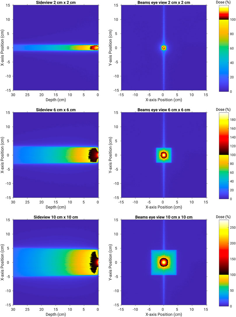
FIGURE 2. 2D dose maps through and on the surface of the water phantom for field sizes of 2 cm × 2 cm (top row), 6 cm × 6 cm (middle row), and 10 cm × 10 cm (bottom row). Doses greater than 100% of the nominal Dmax dose are presented through a second colormap. This clearly highlights the extent of the electron contamination hotspot.
Figure 3 presents the central axis PDD doses as scored from the high-resolution simulation. For each plot, the simulation without the magnetic field is included for reference. The experimental data points are included at the various depths measured. There is generally good agreement between the experimental data points and the simulations when the magnetic field was included. The measured values for the 70 μm skin doses in the presence of the in-line magnetic field from Monte Carlo simulations and the experiment are summarized in Table 1.
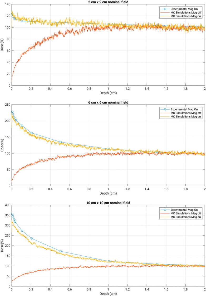
FIGURE 3. Depth dose curves for the nominal field sizes of 2 cm × 2 cm, 6 cm × 6 cm, and 10 cm × 10 cm. Experimental data were collected with MOSkin™ in 1 T MRI-Linac. MC simulation results were obtained with a magnetic field on and off for comparison.
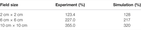
TABLE 1. Surface dose (70 μm depth) comparison between the Monte Carlo simulations and the previously conducted experimental measurements using the MOSkin™ detector. Each of the field sizes is within a ±5% match between the experiment and simulation values. The experimental measurements had an uncertainly in the order of ±3.5%.
As shown in Figure 2, the Monte Carlo simulations provide exceptional insight into the origin of the unique surface dose hotspots observed on the Australian MRI-Linac prototype. It is clearly linked to the focusing of a vast number of secondary electrons produced by the parent x-ray beam as it transports from the MLCs down to the water phantom. These electrons are usually randomly scattered in the air, but the presence of the in-line magnetic field influences the track of the electrons and converges them toward the beam central axis which causes the highspot on the surface of the skin. This stronger focusing effect of the in-line magnetic field increases with the field size. This is mainly because of the fact that as the field size increases, more electrons are scattered from the linac component. As the scattering ratio is large for the larger field sizes, it can be seen from the results that the electron focusing effect is more pronounced for 6 cm × 6 cm and is largest for 10 cm × 10 cm.
As outlined in Table 1, the experimental skin dose values from Monte Carlo simulations are found to be in good agreement, ±10%, with the experimental data. There is apparently a small over-response in the MOSkin™ values for the larger field sizes as compared with the Monte Carlo simulations. It is expected due to the over response of silicon to low-energy (kilovoltage) photons as the photoelectric effect is dominant for higher Z materials in the low energy spectrum. The larger field sizes will have a greater proportion of low-energy electrons incident on the detector. It is due to this reason that for larger field sizes, the agreement between Monte Carlo values and experimentally measured skin dose is found to be in ±10% agreement.
The good match observed in these detailed simulations provides good confidence in broadening the types of simulations and dose planning studies so that the electron contamination hotspot can be further characterized. Being able to conduct accurate skin dose simulations is a powerful and efficient tool that will be key in progressing the dose planning stages of the MRI-Linac prototype system.
The skin or surface dosimetry of the Australian MRI-Linac prototype system has been modeled in detail using Geant4 Monte Carlo simulations coupled with magnetic field data from COMSOL Multiphysics simulations of the MRI system. This modeling enables us to clearly observe the origins of the unusually high surface doses through a unique process of electron contamination focusing toward the beam central axis. These surface dose hotspots at 70 μm depth are shown to rapidly exceed the dose at Dmax as the x-ray beam field size increases. Most importantly, these predictions are correspondingly within ±10% of the values seen using MOSkin™ experimental methods of the same scenarios. These simulations will serve as a robust tool to grow confidence in the clinical dose planning stages currently being pursued within the Australian MRI-Linac Program of Research.
The raw data supporting the conclusion of this article will be made available by the authors, without undue reservation.
BO conceived the original idea. This was discussed with PM and all the other authors. The main text of the manuscript was written by MT and BO. All the other authors have given their valuable suggestions and helped in editing the manuscript.
The authors acknowledge funding from NHMRC Program Grant No. 1132471 and ARC Discovery Grant No. DP120100821.
The authors declare that the research was conducted in the absence of any commercial or financial relationships that could be construed as a potential conflict of interest.
The handling editor declared a past co-authorship with several of the authors: EP, PM, AR, and BO.
All claims expressed in this article are solely those of the authors and do not necessarily represent those of their affiliated organizations, or those of the publisher, the editors, and the reviewers. Any product that may be evaluated in this article, or claim that may be made by its manufacturer, is not guaranteed or endorsed by the publisher.
1. Raaymakers BW, Jürgenliemk-Schulz IM, Bol GH, Glitzner M, Kotte ANTJ, van Asselen B, et al. First Patients Treated with a 1.5 T MRI-Linac: Clinical Proof of Concept of a High-Precision, High-Field MRI Guided Radiotherapy Treatment. Phys Med Biol (2017) 62:L41–L50. doi:10.1088/1361-6560/aa9517
2. Mutic S, Dempsey JF. The ViewRay System: Magnetic Resonance-Guided and Controlled Radiotherapy. Semin Radiat Oncol (2014) 24:196–9. doi:10.1016/j.semradonc.2014.02.008
3. Raaymakers BW, Raaijmakers AJE, Kotte ANTJ, Jette D, Lagendijk JJW. Integrating a MRI Scanner with a 6 MV Radiotherapy Accelerator: Dose Deposition in a Transverse Magnetic Field. Phys Med Biol (2004) 49:4109–18. doi:10.1088/0031-9155/49/17/019
4. Raaijmakers AJE, Raaymakers BW, Lagendijk JJW. Integrating a MRI Scanner with a 6 MV Radiotherapy Accelerator: Dose Increase at Tissue-Air Interfaces in a Lateral Magnetic Field Due to Returning Electrons. Phys Med Biol (2005) 50:1363–76. doi:10.1088/0031-9155/50/7/002
5. Raaijmakers AJE, Raaymakers BW, Meer Sv. d., Lagendijk JJW. Integrating a MRI Scanner with a 6 MV Radiotherapy Accelerator: Impact of the Surface Orientation on the Entrance and Exit Dose Due to the Transverse Magnetic Field. Phys Med Biol (2007) 52:929–39. doi:10.1088/0031-9155/52/4/005
6. Raaijmakers AJE, Raaymakers BW, Lagendijk JJW. Experimental Verification of Magnetic Field Dose Effects for the MRI-Accelerator. Phys Med Biol (2007) 52:4283–91. doi:10.1088/0031-9155/52/14/017
7. Raaijmakers AJE, Raaymakers BW, Lagendijk JJW. Magnetic-field-induced Dose Effects in MR-Guided Radiotherapy Systems: Dependence on the Magnetic Field Strength. Phys Med Biol (2008) 53:909–23. doi:10.1088/0031-9155/53/4/006
8. Kirkby C, Stanescu T, Rathee S, Carlone M, Murray B, Fallone BG. Patient Dosimetry for Hybrid MRI-Radiotherapy Systems. Med Phys (2008) 35(3):1019–27. doi:10.1118/1.2839104
9. Meijsing I, Raaymakers BW, Raaijmakers AJE, Kok JGM, Hogeweg L, Liu B, et al. Dosimetry for the MRI Accelerator: the Impact of a Magnetic Field on the Response of a Farmer NE2571 Ionization Chamber. Phys Med Biol (2009) 54:2993–3002. doi:10.1088/0031-9155/54/10/002
10. Reynolds M, Fallone BG, Rathee S. Dose Response of Selected Ion chambers in Applied Homogeneous Transverse and Longitudinal Magnetic fields. Med Phys (2013) 40(7):042102. doi:10.1118/1.4794496
11. Reynolds M, Fallone BG, Rathee S. Dose Response of Selected Solid State Detectors in Applied Homogeneous Transverse and Longitudinal Magnetic fields. Med Phys (2014) 41(12):092103. doi:10.1118/1.4893276
12. Smit K, van Asselen B, Kok JGM, Aalbers AHL, Lagendijk JJW, Raaymakers BW. Towards Reference Dosimetry for the MR-Linac: Magnetic Field Correction of the Ionization Chamber reading. Phys Med Biol (2013) 58:5945–57. doi:10.1088/0031-9155/58/17/5945
13. Oborn BM, Metcalfe PE, Butson MJ, Rosenfeld AB. High Resolution Entry and Exit Monte Carlo Dose Calculations from a Linear Accelerator 6 MV Beam under the Influence of Transverse Magnetic fields. Med Phys (2009) 36(8):3549–59. doi:10.1118/1.3157203
14. Oborn BM, Metcalfe PE, Butson MJ, Rosenfeld AB. Monte Carlo Characterization of Skin Doses in 6 MV Transverse Field MRI-Linac Systems: Effect of Field Size, Surface Orientation, Magnetic Field Strength, and Exit Bolus. Med Phys (2010) 37:5208–17. doi:10.1118/1.3488980
15. Bielajew AF. The Effect of strong Longitudinal Magnetic fields on Dose Deposition from Electron and Photon Beams. Med Phys (1993) 20:1171–9. doi:10.1118/1.597149
16. S Ramahi SN, Chu J. Achieving a Smaller Penumbra Region for Better Planning in Conformal Radiotherapy by Using a Longitudinal Magnetic Field. Annu Int Conf IEEE Eng Med Biol Soc (2000) 22:3260–3.
17. Naqvi SA, Li XA, Ramahi SW, Chu JC, Ye S-J. Reducing Loss in Lateral Charged-Particle Equilibrium Due to Air Cavities Present in X-ray Irradiated media by Using Longitudinal Magnetic fields. Med Phys (2001) 28:603–11. doi:10.1118/1.1357816
18. Litzenberg DW, Fraass BA, McShan DL, O'Donnell TW, Roberts DA, Becchetti FD, et al. An Apparatus for Applying strong Longitudinal Magnetic fields to Clinical Photon and Electron Beams. Phys Med Biol (2001) 46:N105–N115. doi:10.1088/0031-9155/46/5/401
19. Chen Y, Bielajew AF, Litzenberg DW, Moran JM, Becchetti FD. Magnetic Confinement of Electron and Photon Radiotherapy Dose: A Monte Carlo Simulation with a Nonuniform Longitudinal Magnetic Field. Med Phys (2005) 32:3810–8. doi:10.1118/1.2011091
20. Kirkby C, Murray B, Rathee S, Fallone BG. Lung Dosimetry in a Linac-MRI Radiotherapy Unit with a Longitudinal Magnetic Field. Med Phys (2010) 37:4722–32. doi:10.1118/1.3475942
21. Fallone BG, Murray B, Rathee S, Stanescu T, Steciw S, Vidakovic S, et al. First Mr Images Obtained during Megavoltage Photon Irradiation from a Prototype Integrated Linac-MR System. Med Phys (2009) 36:2084–8. doi:10.1118/1.3125662
22. Fallone BG. The Rotating Biplanar Linac-Magnetic Resonance Imaging System. Semin Radiat Oncol (2014) 24:200–2. doi:10.1016/j.semradonc.2014.02.011
23. Padikal TN, Deye JA. Electron Contamination of a High-Energy X-ray Beam. Phys Med Biol (1978) 23:1086–92. doi:10.1088/0031-9155/23/6/004
24. Nilsson B, Brahme A. Absorbed Dose from Secondary Electrons in High Energy Photon Beams. Phys Med Biol (1979) 24:901–12. doi:10.1088/0031-9155/24/5/003
25. Biggs PJ, Russell MD. An Investigation into the Presence of Secondary Electrons in Megavoltage Photon Beams (Radiotherapy Application). Phys Med Biol (1983) 28:1033–43. doi:10.1088/0031-9155/28/9/003
26. Petti PL, Goodman MS, Gabriel TA, Mohan R. Investigation of Buildup Dose from Electron Contamination of Clinical Photon Beams. Med Phys (1983) 10:18–24. doi:10.1118/1.595287
27. Yorke ED, Ling CC, Rustgi S. Air-generated Electron Contamination of 4 and 10 MV Photon Beams: a Comparison of Theory and experiment. Phys Med Biol (1985) 30:1305–14. doi:10.1088/0031-9155/30/12/004
28. Petti PL, Goodman MS, Sisterson JM, Biggs PJ, Gabriel TA, Mohan R. Sources of Electron Contamination for the Clinac-35 25-MV Photon Beam. Med Phys (1983) 10:856–61. doi:10.1118/1.595348
29. Ahnesjo A, Andreo P. Determination of Effective Bremsstrahlung Spectra and Electron Contamination for Photon Dose Calculations. Phys Med Biol (1989) 34:1451–64. doi:10.1088/0031-9155/34/10/008
30. Sjögren R, Karlsson M. Electron Contamination in Clinical High Energy Photon Beams. Med Phys (1996) 23(11):1873–81. doi:10.1118/1.597750
31. Zhu TC, Palta JR. Electron Contamination in 8 and 18 MV Photon Beams. Med Phys (1997) 25(1):12–9. doi:10.1118/1.598169
32. Medina AL, Teijeiro A, Garcia J, Esperon J, Terron JA, Ruiz DP, et al. Characterization of Electron Contamination in Megavoltage Photon Beams. Med Phys (2005) 32(5):1281–92. doi:10.1118/1.1895793
33. Oborn BM, Metcalfe PE, Butson MJ, Rosenfeld AB, Keall PJ. Electron Contamination Modeling and Skin Dose in 6 MV Longitudinal Field MRIgRT: Impact of the MRI and MRI Fringe Field. Med Phys (2012) 39:874–90. doi:10.1118/1.3676181
34. Oborn BM, Kolling S, Metcalfe PE, Crozier S, Litzenberg DW, Keall PJ. Electron Contamination Modeling and Reduction in a 1 T Open Bore Inline MRI-Linac System. Med Phys (2014) 41(15):051708. doi:10.1118/1.4871618
35. Begg J, Alnaghy SJ, Causer T, Alharthi T, George A, Glaubes L, et al. Technical Note: Experimental Characterization of the Dose Deposition in Parallel MRI‐linacs at Various Magnetic Field Strengths. Med Phys (2019) 46:5152–8. doi:10.1002/mp.13767
Keywords: MRI-guided radiotherapy, skin dose, dosimetry, magnetic fields, in-line MRI-Linac, electron contamination
Citation: Tai M, Patterson E, Metcalfe PE, Rosenfeld A and Oborn BM (2022) Skin Dose Modeling and Measurement in a High Field In-Line MRI-Linac System. Front. Phys. 10:902744. doi: 10.3389/fphy.2022.902744
Received: 23 March 2022; Accepted: 16 May 2022;
Published: 27 June 2022.
Edited by:
Urszula Jelen, Genesis Care, AustraliaReviewed by:
Zoe Moutrie, New South Wales Department of Health, AustraliaCopyright © 2022 Tai, Patterson, Metcalfe, Rosenfeld and Oborn. This is an open-access article distributed under the terms of the Creative Commons Attribution License (CC BY). The use, distribution or reproduction in other forums is permitted, provided the original author(s) and the copyright owner(s) are credited and that the original publication in this journal is cited, in accordance with accepted academic practice. No use, distribution or reproduction is permitted which does not comply with these terms.
*Correspondence: Madiha Tai, bXQ2NjBAdW93bWFpbC5lZHUuYXU=
Disclaimer: All claims expressed in this article are solely those of the authors and do not necessarily represent those of their affiliated organizations, or those of the publisher, the editors and the reviewers. Any product that may be evaluated in this article or claim that may be made by its manufacturer is not guaranteed or endorsed by the publisher.
Research integrity at Frontiers
Learn more about the work of our research integrity team to safeguard the quality of each article we publish.