- 1MOE Key Laboratory for Nonequilibrium Synthesis and Modulation of Condensed Matter, School of Physics, Xi’an Jiaotong University, Xi’an, China
- 2Shaanxi Province Key Laboratory of Quantum Information and Quantum Optoelectronic Devices, School of Physics, Xi’an Jiaotong University, Xi’an, China
Three-dimensional polymorphic beams (3D PBs) with arbitrary 3D curves have drawn increasing attention. In this paper, we introduce the concept of phase gradient parameter (PGP) to describe the accumulation of phase along the curvilinear trajectory of a PB. To determine the magnitude and sign of the integral and fractional PGP of 3D PBs, we present an effective method called slightly defocused interference (SDI). The idea is based on the coaxial interference of two polymorphic beams of the same shape but various PGP. One of the interfered beams is slightly defocused, enabling the identification of the sign of the PGP. The efficiency of the reported method has been demonstrated with numerical simulations and experimental measurements by applying it to determining the PGP of various types of polymorphic beams. The results show high quality, indicating great potential in the applications of beam shaping.
Introduction
Vortex beams (VBs), with spiral wavefront and well-defined orbital angular momentum distribution, have been serving as powerful tools in many fields [1–3]. Recently, three-dimensional polymorphic beams (3D PBs) have been proposed, advancing the symmetric vortex beam to freestyle 3D beams with arbitrary intensity trajectory [4, 5]. Due to the high-intensity gradient and programmable phase gradient, 3D PBs have inspired widespread applications, especially in the study of multi-particle dynamics in optical traps [6, 7]. In this case, the phase gradient of 3D PBs plays a critical role in the beams’ focusing properties, further the optical force to drive the particle moving along the trajectory. To describe the phase gradient of 3D PBs, we introduce the concept of the phase gradient parameter (PGP). For the PBs with closed curve trajectories, such as ring-shaped beams, the phase accumulation is 2π times the PGP. In this case, the PGP is the well-known topological charge (TC) [7]. It is of significance to precisely determine the PGP of 3D PBs. Methods based on interference or diffraction have been reported for determining the TC of VBs [8–10]. The diffraction methods often use diffractive elements, such as triangular apertures [11], cylindrical lens [12, 13], and parabolic-line linear grating [14-16], to measure circular symmetric VBs. While the interference methods are mainly divided into two categories: self-interference and reference beam interference. The typical self-interference method is using Mach-Zehnder interferometer [17, 18]. By investigating the interference pattern of the vortex beam and its conjugate beam, the sign and the magnitude of the TC can be resolved. Utilizing a plane or spherical reference beam to interfere with a vortex beam is also a very popular method [19-21]. However, these methods are limited to VBs with two-dimensional (2D) simple intensity patterns. It is an ongoing task to simultaneously determine the magnitude and sign of integral and fractional PGP of 3D PBs. As far as we know, no method to this issue has been reported. In this Letter, we present an enhanced holographic approach termed slightly defocused interference (SDI) to simultaneously determine the PGP of 3D PBs with high precision.
Slightly Defocused Interference Method
We employed the holographic beam shaping technique reported by Rodrigo JA et al. [4, 5] to generate 3D PBs with specially prescribed intensity distribution and well-defined orbital angular momentum distribution. The complex amplitude of a PB satisfies
In Eq. 1, r = (x, y) is the spatial coordinates at the input plane. c3(t) = (x0(t), y0(t), z0(t)) denotes a 3D curve with (x0, y0, z0) being the Cartesian coordinates.
and
where t ∈ [0, T],
where M = 1+sinc−1[Arelg(x, y)]/π is the modulation function, φrelg(x, y) is a total relative phase, Arelg(x, y) is the relative field amplitude.
The SDI scheme is based on the interference between two PBs with the same intensity curve, but different PGP. The target beam has the expected PGP values, and the reference beam, however, has the PGP of zero and is slightly defocused. The Fresnel lens phase φLens is used to control the convergence of the reference beam, written as
Here, λ is the wavelength, f′ is the focal length of the Fresnel lens, h is the defocusing distance from the focal plane. By setting an appropriate value of h, the reference beam will be slightly defocused with respect to the target beam. As an illustration, we used a PB with a ring trajectory by setting the parameters of the target beam as follow: x0(t) = R0cos(t), y0(t) = R0sin(t), R0 = 300μm, and m = 10 (Figure 1E), and verified the performance of the SDI method in determining the PGP by simulation. The interference field between the target and reference beams can be expressed by
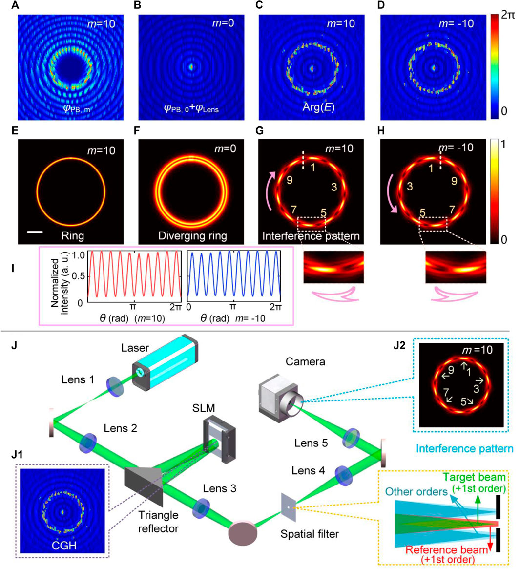
FIGURE 1. Simulation results of determination of PGP of ring-shaped beams by the SDI method. (A) phase hologram for generation of a ring-shaped beam with m = 10. (B) phase hologram for generating a defocused ring-shaped beam with m = 0 through a Fresnel lens phase. (C,D) phase holograms for generating the interference patterns with m = ±10. (E–H) correspond to the simulated focal plane patterns generated in (A–D). The insets in (G,H) show the detail of the interference fringes. (I) The azimuthal intensity profiles of the interference patterns in (G,H). Scale bar: 100 μm. (J) The schematic of the experimental setup. (J1) The complex amplitude coded hologram. (J2) The interference pattern with m = 10.
Here, C is a constant for adjusting the amplitude of the reference beam, φPB,m and φPB,0 denote the complex amplitude-coded phase (Figures 1A,B) for generating the target ring-shaped beam with m = 10 (Figure 1E) and the reference ring-shaped beam with m = 0. The slightly defocused reference beam as shown in Figure 1F. By directly calculating the argument of the optical field E, i.e., Arg(E), the complex amplitude-coded phase holograms (Figures 1C,D) to be displayed on the SLM for generating the interference patterns with m = 10 (Figure 1G) and m = −10 (Figure 1H) are obtained. The slight defocusing enables the determination of the sign of the PGP. We can see that the interference patterns are divided into 10 fringes, equal to the magnitude of PGP of the target PB. Figure 1I shows the azimuthal intensity profiles of the interference patterns with the dotted lines in Figures 1G,H are the start point. The red and the blue curves (Figure 1I) both show periodic curves with a period of 2π/10 for m = 10 and −10, respectively, proving that the magnitude of PGP is 10.
Particularly worth mentioning is that the sign of PGP can be obtained intuitively by observing the arrow-shaped fringes’ direction. As indicated by the pink arrows shown in the inset of Figures 1G,H, when PGP > 0, the pointed end of the “arrow” is along the clockwise direction. In comparison, it is counterclockwise for PGP < 0. Therefore, by appropriately setting the parameter C and the lens phase φLens, the sign of the PGP can be precisely determined.
Experimental Setup
As shown in Figure 1J, a 532 nm laser first passed through a beam expander consisting of Lenses 1 and 2. Then the beam illuminated a phase-only SLM [the resolution is 1920 × 1080, Pluto-NIR-II (HOLOEYE Photonics AG Inc., Germany)]. The complex amplitude-coded phase hologram (Figure 1J1) was addressed on the SLM to modulate the input beam. The modulated beam was then reflected by the triangle reflector and relayed to the back focal plane of Lens 5 by the 4f system consisting of Lenses 3 and 4. A spatial filter (the aperture size is 2 mm) placed at the focal plane of Lenses 3 and 4 to block the other order diffractions except for the +first order, including the target beam and the slightly defocused reference beam. To register the results, we employed a camera (the resolution is 1280 × 1024 and the pixel size is 5.3 μm, DCC3240M (Thorlabs, America)) at the focal plane of Lens 5.
Results and Discussion
We first experimentally demonstrated the SDI method in determining the PGP of different integral 2D PBs as shown Figure 2, including square-shaped beam (x0(t) = 3R0cos(t)+7R0cos(3t)/20, y0(t) = 3R0sin(t)-7R0sin(3t)/20, Figure 2A), ring-shaped beam (x0(t) = R0cos(t), y0(t) = R0sin(t), Figure 2B), star-like beam (x0(t) = r(t)R0cos(t), y0(t) = r(t)R0sin(t), r(t) = 1−cos(4t)/4, Figure 2C), and S-like beam (Figure 2D. When the curve is nonparametric, c3(t) can be approximated by a set of linked Bézier curves [23]). The experimentally measured intensity distributions of these four types of PBs are shown in the first row. The measured interference patterns for various PGP are presented in rows 2–5. For m = 1, 10, 15, −15, 20, and −20, the interference fringes exhibit respective 1, 10, 15, and 20 petals along the curve, respectively; the number of petals happens to be the absolute value of the corresponding PGP. From rows 4 and 5, we can find that the PGP of any two PBs in the same column has opposite signs, as indicated by the pink arrows. Each segment magically shows an “arrow” shape, just like a polymorphic snake, making the interference patterns explicitly spiral out in the anticlockwise direction (row 4, PGP > 0) or anticlockwise direction (row 5, PGP < 0). These features allow us to readily determine the sign of PGP. In addition, for non-closed beams with arbitrary trajectories, such as S-like PBs (Figure 2D), the SDI method still performs well in determining PGP.
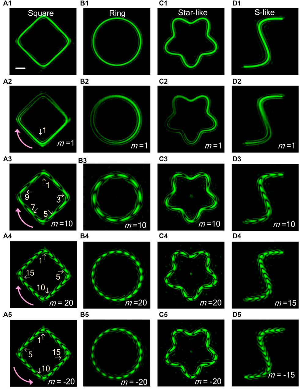
FIGURE 2. Experimental results for determining the integral PGP of 2D PBs. The (A1–D1) in the figure respectively shows the intensity distribution of square-shaped beam, ring-shaped beam, star-like beam, and S-like beam. (A2–D5) are the interference patterns of PBs with m = 1, 10, 20, −20, R0 = 300 μm, except for (D4) and (D5), which are the interference patterns of the S-like beam with m = ±15. Scale bar: 100 μm.
The VBs with fractional PGP possess unique intensity distribution and more sophisticated orbital angular momentum modulation dimension [24, 25]. Therefore, it is of great significance to determine the fractional PGP. The simulation and experimental results using the SDI method have shown high quality, making the determination of fractional PGP a possible mission. Figure 3 shows the numerically simulated (Figures 3A,B) and experimentally measured (Figures 3C,D) interference results of the ring-shaped beams with m = 3.1, 3.3, 3.5, 3.7 and 3.9 using the SDI method. When the PGP increases gradually, one of the fringes of the interference pattern breaks, and a fourth interference fringe gradually appears (as indicated by the insets in Figures 3A,C. Figure 3B is the one-dimensional azimuthal intensity profile curves along the trajectory of the interference patterns (Figure 3A). Denote by θint the angle subtended by the arc between two adjacent valleys of the curve (yellow shaded region in Figure 3B which corresponds to an unbroken fringe marked with “Int”) and denote by θfrac the angle associated with the arc of broken the fringes (marked with “Frac”) between two adjacent valleys of the curve (the blue shaded region in Figure 3B). The whole PGP can be deduced from θfrac/θint + 2, or 2π/θint.
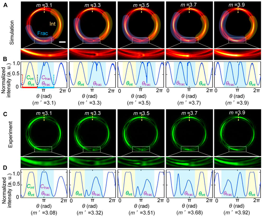
FIGURE 3. Results for determining the fractional PGP. (A) are the evolution of the interference patterns of ring-shaped Beams with m = 3.1, 3.3, 3.5, 3.7 and 3.9. (B) Azimuthal intensity profiles of the interference patterns in (A). (C,D) are the corresponding experiment results. Scale bar: 100 μm.
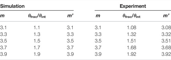
The measured results of the arc length ratio θfrac/θint from Figures 3B,D are shown in table 1. For m = 3.1, 3.3, 3.5, 3.7 and 3.9, the simulated ratios θfrac/θint are 1.1, 1.3, 1.5, 1.7, and 1.9. Correspondingly the determined PGP are m′ = 3.1, 3.3, 3.5, 3.7, and 3.9. The accuracy of the simulated results depends on the step size of the azimuthal intensity curve calculated by the program. In our simulations, it was set to 10,000, making the measuring relative error smaller than 10–3. In theory, the numerically measured PGP is equal to the designed PGP. The experimentally measured ratios θfrac/θint are 1.08, 1.32, 1.51, 1.68, and 1.92. Therefore, the determined PGP are m′ = 3.08, 3.32, 3.51, 3.68, and 3.92, respectively. Compared with the simulation results, the experimental results showed small deviation from the theoretical values, which is attributed to the influence of background stray light, and the limited beam shaping resolution. However, the measuring error is less than 0.03, demonstrating the high feasibility of the SDI method.
Importantly, the SDI method can be applied to determining the PGP of the 3D PBs. The PBs with tilted-ring shape and waved-ring shape are taken as examples to demonstrate the determination of the PGP of 3D PBs. In Figure 4, columns 1 and 2 are the numerical simulation results of the 3D view of PBs and the interference intensity profiles with m = ±10, respectively. By moving the camera in the axial direction to scan the beam, we can record the 2D intensity images of the beam at a sequence of axial positions. The 3D patterns are constructed with these 2D images, as shown in columns 3 and 4. Column 5 provides the cross-section intensities at different axial positions before the focal plane. Again, we can find that the light curves of the 3D PBs are divided into 10 fringes, equivalent to the value of the PGP. Notably, the sign is determined by the direction of the “arrows” of the interference fringes in column 5 as theoretically predicted. Moreover, the fractional PGP of 3D PBs can also be detected by analyzing the intensity profile curve of the maximum projection of the interference pattern in the z-direction.
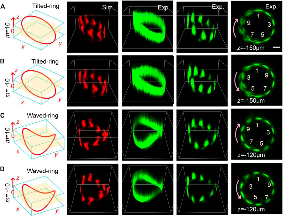
FIGURE 4. Determination of PGP of 3D PBs. (A,B) Tilted-ring with m = ±10. (C,D) Waved-ring with m = ±10. Columns 1 and 2 are the numerical simulation results of the 3D view of PBs and the interference intensity profiles. Columns 3 and 4 are the corresponding experimental results. Column 5 displays the beam propagated before the focal plane. Scale bar: 100 μm.
Conclusion and Discussion
In conclusion, we have reported the SDI method for quantitatively determining the integral and fractional PGP of PBs with high accuracy. The experimental results are in good agreement with the theoretical predictions. The SDI method holds great promise to be a powerful tool for studying the properties of 3D PBs, and thus great potential in applying to various fields, such as optical tweezers, optical communications, etc.
Although the fractional PGP of 3D PBs with simple geometry can be detected by the SDI method, for more complex-shaped beams, such as the optical solenoid beam [26], the measurement of the fractional PGP is still limited due to the overlap of the light field projections in the z-direction. In future work, we will consider the multi-angle projection to detect the PGP of the complex-shaped beams. Recently, a deep learning method named “VortexNet” can accurately reveal the topological properties [27]. In view of the strong performance of this method, we plan to combine the SDI method with the deep learning approach. In this way, we would expect to achieve a higher-precision measurement of the PGP.
Data Availability Statement
The original contributions presented in the study are included in the article/Supplementary Material, further inquiries can be directed to the corresponding author.
Author Contributions
ML and YL conceived and designed the study. XY and YL designed the system and collected data. XY and MH prepared the samples. All authors contributed to results interpretation. XY and YL drafted the manuscript, to which all authors contributed.
Funding
Financial support was provided by the Innovation Capability Support Program of Shaanxi (Program No. 2021TD-57); Natural Science Foundation of China (NSFC) (Nos 61905189, 62135003, 62005208); Natural Science Basic Research Program of Shaanxi (No 2022JZ-34); China Postdoctoral Science Foundation (Nos 2019M663656, 2020M673365).
Conflict of Interest
The authors declare that the research was conducted in the absence of any commercial or financial relationships that could be construed as a potential conflict of interest.
Publisher’s Note
All claims expressed in this article are solely those of the authors and do not necessarily represent those of their affiliated organizations, or those of the publisher, the editors and the reviewers. Any product that may be evaluated in this article, or claim that may be made by its manufacturer, is not guaranteed or endorsed by the publisher.
References
1. Allen L, Beijersbergen MW, Spreeuw RJC, Woerdman JP. Orbital Angular Momentum of Light and the Transformation of Laguerre-Gaussian Laser Modes. Phys Rev A (1992) 45(11):8185–9. doi:10.1103/physreva.45.8185
2. Bozinovic N, Yue Y, Ren Y, Tur M, Kristensen P, Huang H, et al. Terabit-Scale Orbital Angular Momentum Mode Division Multiplexing in Fibers. science (2013) 340(6140):1545–8. doi:10.1126/science.1237861
3. Zhang K, Wang Y, Yuan Y, Burokur SN. A Review of Orbital Angular Momentum Vortex Beams Generation: From Traditional Methods to Metasurfaces. Appl Sci (2020) 10(3):1015. doi:10.3390/app10031015
4. Rodrigo JA, Alieva T. Polymorphic Beams and Nature Inspired Circuits for Optical Current. Sci Rep (2016) 6(1):35341–8. doi:10.1038/srep35341
5. Rodrigo JA, Alieva T, Abramochkin E, Castro I. Shaping of Light Beams along Curves in Three Dimensions. Opt Express (2013) 21(18):20544–55. doi:10.1364/oe.21.020544
6. Rodrigo JA, Angulo M, Alieva T. All-Optical Motion Control of Metal Nanoparticles Powered by Propulsion Forces Tailored in 3d Trajectories. Photon Res (2021) 9(1):1–12. doi:10.1364/prj.408680
7. Amaral AM, Falcão-Filho EL, de Araújo CB. Characterization of Topological Charge and Orbital Angular Momentum of Shaped Optical Vortices. Opt Express (2014) 22(24):30315–24. doi:10.1364/oe.22.030315
8. Fickler R, Campbell G, Buchler B, Lam PK, Zeilinger A. Quantum Entanglement of Angular Momentum States with Quantum Numbers up to 10,010. Proc Natl Acad Sci U.S.A (2016) 113(48):13642–7. doi:10.1073/pnas.1616889113
9. Ma H, Li X, Tai Y, Li H, Wang J, Tang M, et al. In Situ Measurement of the Topological Charge of a Perfect Vortex Using the Phase Shift Method. Opt Lett (2017) 42(1):135–8. doi:10.1364/ol.42.000135
10. Bianchetti A, Etchepareborda P, Federico A. Determining the Fractional Topological Charge Shifting in Perfect Vortices from Laser Speckle. Opt Commun (2019) 441:74–9. doi:10.1016/j.optcom.2019.02.051
11. de Araujo LEE, Anderson ME. Measuring Vortex Charge with a Triangular Aperture. Opt Lett (2011) 36(6):787–9. doi:10.1364/ol.36.000787
12. Alperin SN, Niederriter RD, Gopinath JT, Siemens ME. Quantitative Measurement of the Orbital Angular Momentum of Light with a Single, Stationary Lens. Opt Lett (2016) 41(21):5019–22. doi:10.1364/ol.41.005019
13. Kotlyar VV, Kovalev AA, Porfirev AP. Astigmatic Transforms of an Optical Vortex for Measurement of its Topological Charge. Appl Opt (2017) 56(14):4095–104. doi:10.1364/ao.56.004095
14. Amiri P, Mardan Dezfouli A, Rasouli S. Efficient Characterization of Optical Vortices via Diffraction from Parabolic-Line Linear Gratings. J Opt Soc Am B (2020) 37(9):2668–77. doi:10.1364/josab.398143
15. Rasouli S, Amiri P, Kotlyar VV, Kovalev AA. Characterization of a Pair of Superposed Vortex Beams Having Different Winding Numbers via Diffraction from a Quadratic Curved-Line Grating. J Opt Soc Am B (2021) 38(8):2267–76. doi:10.1364/josab.428390
16. Rasouli S, Fathollazade S, Amiri P. Simple, Efficient and Reliable Characterization of Laguerre-Gaussian Beams with Non-zero Radial Indices in Diffraction from an Amplitude Parabolic-Line Linear Grating. Opt Express (2021) 29(19):29661–75. doi:10.1364/oe.435116
17. Leach J, Padgett MJ, Barnett SM, Franke-Arnold S, Courtial J. Measuring the Orbital Angular Momentum of a Single Photon. Phys Rev Lett (2002) 88(25):257901. doi:10.1103/physrevlett.88.257901
18. Kumar P, Nishchal NK. Modified Mach-Zehnder Interferometer for Determining the High-Order Topological Charge of Laguerre-Gaussian Vortex Beams. J Opt Soc Am A (2019) 36(8):1447–55. doi:10.1364/josaa.36.001447
19. Cui S, Xu B, Luo S, Xu H, Cai Z, Luo Z, et al. Determining Topological Charge Based on an Improved Fizeau Interferometer. Opt Express (2019) 27(9):12774–9. doi:10.1364/oe.27.012774
20. Pan S, Pei C, Liu S, Wei J, Wu D, Liu Z, et al. Measuring Orbital Angular Momentums of Light Based on Petal Interference Patterns. OSA Continuum (2018) 1(2):451–61. doi:10.1364/osac.1.000451
21. Liang Y, Yan S, He M, Li M, Cai Y, Wang Z, et al. Generation of a Double-Ring Perfect Optical Vortex by the Fourier Transform of Azimuthally Polarized Bessel Beams. Opt Lett (2019) 44(6):1504–7. doi:10.1364/ol.44.001504
22. Bolduc E, Bent N, Santamato E, Karimi E, Boyd RW. Exact Solution to Simultaneous Intensity and Phase Encryption with a Single Phase-Only Hologram. Opt Lett (2013) 38(18):3546–9. doi:10.1364/ol.38.003546
23. Rodrigo JA, Angulo M, Alieva T. Dynamic Morphing of 3d Curved Laser Traps for All-Optical Manipulation of Particles. Opt Express (2018) 26(14):18608–20. doi:10.1364/oe.26.018608
24. Tao SH, Yuan X-C, Lin J, Peng X, Niu HB. Fractional Optical Vortex Beam Induced Rotation of Particles. Opt Express (2005) 13(20):7726–31. doi:10.1364/opex.13.007726
25. Zhang H, Zeng J, Lu X, Wang Z, Zhao C, Cai Y. Review on Fractional Vortex Beam. Nanophotonics (2022) 11(2):241–73. doi:10.1515/nanoph-2021-0616
26. Lee S-H, Roichman Y, Grier DG. Optical Solenoid Beams. Opt Express (2010) 18(7):6988–93. doi:10.1364/oe.18.006988
Keywords: phase gradient, vortex beams, topological charge (TC), polymorphic beams, orbital angular momentum (OAM)
Citation: Yun X, Liang Y, He M, Guo L, Wang Z, Zhao T, Wang S and Lei M (2022) Determining the Phase Gradient Parameter of Three-Dimensional Polymorphic Beams. Front. Phys. 10:893133. doi: 10.3389/fphy.2022.893133
Received: 10 March 2022; Accepted: 21 March 2022;
Published: 13 April 2022.
Edited by:
Peng Gao, Xidian University, ChinaReviewed by:
Shaohui Yan, Xian Institute of Optics and Precision Mechanics (CAS), ChinaKebin Shi, Peking University, China
Copyright © 2022 Yun, Liang, He, Guo, Wang, Zhao, Wang and Lei. This is an open-access article distributed under the terms of the Creative Commons Attribution License (CC BY). The use, distribution or reproduction in other forums is permitted, provided the original author(s) and the copyright owner(s) are credited and that the original publication in this journal is cited, in accordance with accepted academic practice. No use, distribution or reproduction is permitted which does not comply with these terms.
*Correspondence: Yansheng Liang, eWFuc2hlbmcubGlhbmdAbWFpbC54anR1LmVkdS5jbg==; Ming Lei, bWluZy5sZWlAbWFpbC54anR1LmVkdS5jbg==
 Xue Yun
 Yansheng Liang
 Minru He1,2
 Zhaojun Wang
 Shaowei Wang
 Ming Lei