- School of Electronic Information and Electrical Engineering, Shanghai Jiao Tong University, Shanghai, China
In this study, we present that the plasma sphere can focus and enhance the evanescent and transmitted waves. Electromagnetic waves propagating in a plasma sphere with a positive or negative permittivity, which leads to the enhancement of transmitted and evanescent waves, are analyzed. The intensity of the focused beam can be hundreds of times stronger than that of the incident wave. The enhancement effect is associated with plasma frequency, collision frequency, and incident wave frequency. The results illustrate that the electromagnetic wave can be focused, reflected, and oscillated by controlling the electromagnetic parameters of the plasma sphere. With a strong field enhancement available, it is possible to be used in microwave power amplifiers, plasma antennas, reflectors, etc.
Introduction
The applications of plasma, such as plasma antenna, plasma stealth materials, plasma switches, plasma mirrors, etc.[1–4], are gradually increasing in recent years. Plasmas have a complex permittivity, which depends on the electron density, plasma collision frequency, the frequency of incident electromagnetic waves, etc. They can behave as the dielectric or conductor medium and can be used as a dynamic media for electromagnetic waves. The gas plasma is usually generated by DC discharges, RF discharges, and laser excitation. The ionized gas could be easily switched ON and OFF in a very short time (millisecond). A plasma sphere or cylinder, which is constructed by an insulating tube filled with ionized gas, can be designed to transmit and receive electromagnetic waves, and act as a reconfigurable plasma antenna [5–8]. Borg and Harris [9] measured the radiation patterns of the plasma cylinder and demonstrated that the current distribution can be controlled by the plasma density. Plasma cylinders can be used instead of metal elements in communication antennas. Kumar and Borra [10] carried out experiments to study the power patterns, directivity, and half-power beamwidth of different plasma antennas. The wireless communication and jamming capability of the plasma antenna were tested. Ye [11] analyzed two kinds of mechanisms to explain the radiation of the plasma cylinder antenna. The radiation characteristics of the plasma antenna were compared with those of the metal antenna. Geng et al. [12] studied the electromagnetic scattering of a multilayered plasma sphere by employing the eigenfunction expansions of the fields in terms of spherical vector wave functions and calculated the electromagnetic field distributions. Song et al. [13] investigated the far field of the electromagnetic waves by an inhomogeneous plasma sphere theoretically and experimentally. The effects of the electromagnetic wave frequency and plasma density on the offset angle were discussed. Helaly et al. [14] computed the electromagnetic scattering by a nonuniform plasma sphere, which is represented by the number of concentric spherical shells, each with a fixed electron density.
The internal and near fields of the dielectric sphere have been studied [15–18]. Gouesbet et al. [19] and Lock [20] studied the theoretical development of different expanded descriptions of electromagnetic scattering with a homogeneous spherical particle with the generalized Lorenz–Mie theory. Plasma is not only a dispersive medium but also can be controlled electrically [21]. The electromagnetic properties of plasma, such as permittivity, vary due to the plasma frequency, collision frequency, and incident wave frequency [22]. Plasma could evanescent, reflect, or absorb the electromagnetic wave by simply choosing the appropriate electromagnetic properties together with other parameters.
The charged particles in the plasma are capable of interacting with electromagnetic fields, which leads to many phenomena. In this study, we have studied the properties of near field and internal field for the plasma sphere with positive and negative permittivity. The focusing effects of evanescent and transmitted waves by a plasma sphere have been discussed. The influence of the plasma frequency, the collision frequency, and the incident frequency of electromagnetic waves on the intensity distribution of the focused beam is given. With various parameters of the plasma sphere, the different properties of evanescent and transmitted waves are discussed.
Theories for the Near Field of a Plasma Sphere
The plasma is a medium full of free charge carriers and tends to maintain the electric charge neutral under equilibrium conditions. The electromagnetic waves are incident on the plasma, excite, and perturb plasmas. When the plasma is disturbed from the equilibrium condition due to the thermal and electrical disturbances, the internal fields give rise to collective particle motions, which are characterized by a natural frequency of oscillation known as the (electron) plasma angular frequency
The plasma frequency
We assume that an incident plane wave propagates into a plasma in the direction of the positive z-axis. Considering the effects of electron–neutral collision, the motion equation of the electrons in the plasma under the action of the Lorentz force and collisional forces can be written as [23]
where
where
The transmission of the electromagnetic waves in the plasma sphere is affected by the plasma parameters. According to Eq. 3, the plasma permittivity depends on the incident frequency
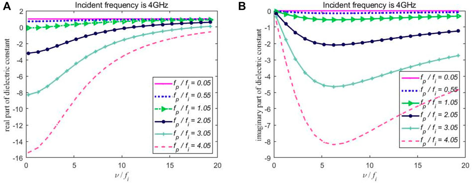
FIGURE 1. The effect of different collision frequencies and plasma frequencies on the (A) real part of plasma permittivity and the (B) imaginary part of plasma permittivity.
The real part of plasma permittivity can be positive or negative, as shown in Figure 1A. When
The dispersion of plasma is caused by the frequency-dependent nature of the plasma–wave interaction. The plasma permittivity parameters can be controlled electrically by changing the plasma frequency, the collision frequency, and the incident frequency. The electromagnetic wave may be evanescent, reflected, or absorbed within the plasma medium depending on the appropriate parameters of plasma and the incident wave.
Interactions between a plasma sphere and the plane wave are analyzed based on the Mie theory [27]. In spherical coordinates
The internal field is given as
The scattered field is given as
where
The boundary conditions, derived from the continuity of the tangential components of fields on the surface of the sphere can be resolved to obtain all unknown expansion coefficients
The prime denotes derivation with respect to the argument,
Simulation Result of Focal Characteristics of a Plasma Sphere
The plane wave is incident on the plasma sphere with a radius
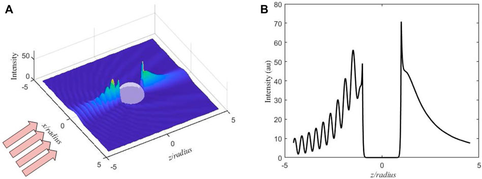
FIGURE 2. The distribution of internal and near fields for a plasma sphere with fi = 2.1 GHz, fp = 9 GHz, νc = 29 GHz. (A) The three-dimensional intensity pattern and (B) the intensity distribution along the z-axis.
The enhancement effect of the evanescent wave by the plasma sphere is associated with plasma frequency and collision frequency. For example, when
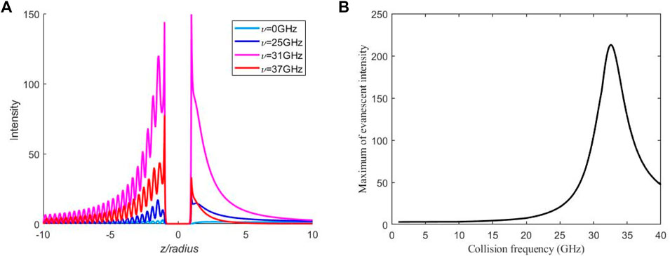
FIGURE 3. The influence of different collision frequencies on (A) the field distribution and (B) the maximum field of the evanescent wave with fi = 2.1 GHz and fp = 9 GHz.
The influence of different plasma frequencies on the field distribution of the plasma sphere with
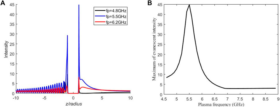
FIGURE 4. (A) The distribution of internal and near fields variation with the plasma frequency and (B) the maximum intensity of the evanescent wave versus the plasma frequency with fi = 2.1 GHz and νc = 4 GHz.
It should also be noted that the enhancement effect of the evanescent wave is not produced in any cases. As shown in Figure 5, most of the incident waves are reflected on the surface of the plasma sphere. But no evanescent wave is enhanced on the shadow-side surface of the sphere, and the electromagnetic wave propagates into the plasma with the intensity slightly increasing along the z direction. This high reflection effect can be achieved by a plasma sphere with negative permittivity.

FIGURE 5. The distribution of internal and near fields with fi = 2.1 GHz, fp = 4 GHz, and νc = 3 GHz: (A) three-dimensional pattern; (B) the field in the plane x–z; and (C) the intensity along the z-axis.
When the real part of plasma permittivity is positive, the electromagnetic waves propagate inside the plasma in a manner similar to wave propagation in a dielectric medium. The dielectric property of plasma is governed by plasma parameters and incident wave frequency. Figure 6 shows the intensity distribution of plasma sphere with
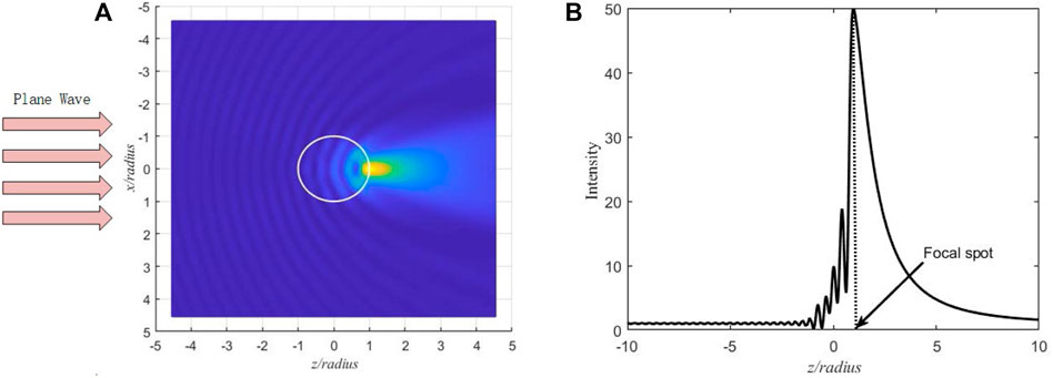
FIGURE 6. Images of internal and near-external fields for a plasma sphere with R = 20 cm, fi = 2.1 GHz, fp = 2 GHz, and νc = 60 GHz. (A) The three-dimensional field distribution in the plane x–z and (B) the intensity distribution along the z-axis.
The plane wave is incident from the left and impinges on the plasma sphere. The focusing field of transmitted waves with narrow and high intensity is observed in the near field of the shadow-side surface. The field is highly confined to the surface along the propagation axis z. The corresponding radial internal and near-external intensity distribution of the plasma sphere along z is shown in Figure 6B. For a given unitary incident plane wave, the intensity maximum outside the plasma sphere is amplified by more than 50 times. On the left side of the main intensity, there are multiple sharp spikes, which have very narrow widths and different intensities. A part of the incident waves is reflected inside the plasma sphere.
The focusing intensity of transmitted waves depends on the plasma parameter. Figure 7 exemplifies the influence of different collision frequencies on the intensity distribution of the plasma sphere with
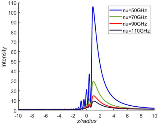
FIGURE 7. The influence of different collision frequencies on the intensity distribution with fi = 2.1 GHz and fp = 2 GHz.
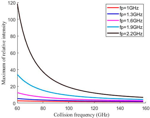
FIGURE 8. The effect of different collision frequencies and plasma frequencies on the maximum intensity of the focal spot at fi = 2.1 GHz.
The characteristics of the intensity distribution of the focal spot also depend on the incident frequency. Figure 9 shows the influence of different incident frequencies on internal and near fields for a plasma sphere with
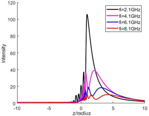
FIGURE 9. The influence of different incident frequencies on internal and near-external fields at fp = 2 GHz and νc = 50 GHz.
It should be mentioned that the focus effect of a plasma sphere requires the parameters, such as collision frequency, plasma frequency, incident frequency, and size of the sphere, to meet certain conditions. For different parameters, the electromagnetic wave can be reflected, oscillated, and transmitted by the plasma sphere. Figure 10 shows the three-dimensional intensity pattern of internal and near fields in the x–z plane with
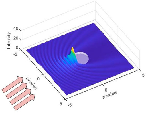
FIGURE 10. The three-dimensional intensity pattern of a plasma sphere at fi = 2.1 GHz, fp = 2 GHz, and νc = 6 GHz.
With a collision frequency of 6 GHz, a plasma frequency of 2 GHz, and an incident frequency of 3 GHz, the incident electromagnetic waves are divided into three parts by the plasma sphere: partially oscillated, partially reflected, and transmitted, as shown in Figure 11. It is observed that most incident electromagnetic waves are confined inside a plasma sphere and form oscillation.
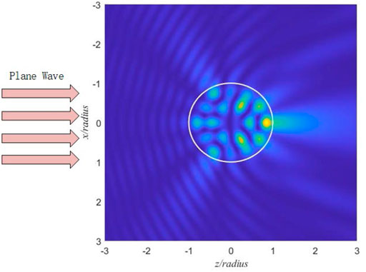
FIGURE 11. The intensity distribution of internal and near fields for a plasma sphere with fi = 3.1 GHz, fp = 2 GHz, and νc = 6 GHz.
Conclusion
The plasma sphere has focus and enhanced features for transmitted and evanescent waves as proved in simulation results. The intensity of the focus spot can reach one hundred times larger than that of the incident wave. The intensity distributions of the internal and near fields for the plasma sphere are determined by electromagnetic parameters, which are collision frequency, plasma frequency, and incident wave frequency. The plasma sphere focuses on evanescent and transmitted waves by controlling the plasma parameters. The plasma offers solutions for the increasing requirements of electromagnetic field enhancement, such as microwave power amplifiers, plasma antennas, and subwavelength imaging applications.
Data Availability Statement
The original contributions presented in the study are included in the article/Supplementary Material, further inquiries can be directed to the corresponding author.
Author Contributions
WS and BY proposed the idea. WS wrote the original manuscript. BY and JM supervised the project.
Conflict of Interest
The authors declare that the research was conducted in the absence of any commercial or financial relationships that could be construed as a potential conflict of interest.
Publisher’s Note
All claims expressed in this article are solely those of the authors and do not necessarily represent those of their affiliated organizations, or those of the publisher, the editors, and the reviewers. Any product that may be evaluated in this article, or claim that may be made by its manufacturer, is not guaranteed or endorsed by the publisher.
References
1. Mathew J, Fernsler RF, Meger RA, Gregor JA, Murphy DP, Pechacek RE, et al. Generation of Large Area, Sheet Plasma Mirrors for Redirecting High Frequency Microwave Beams. Phys Rev Lett (1996) 77:1982–5. doi:10.1103/physrevlett.77.1982
2. Jusoh MT, Lafond O, Colombel F, Himdi M. Performance and Radiation Patterns of a Reconfigurable Plasma Corner-Reflector Antenna. Antennas Wirel Propag Lett (2013) 12:1137–40. doi:10.1109/lawp.2013.2281221
3. Manheimer WM. Plasma Reflectors for Electronic Beam Steering in Radar Systems. IEEE Trans Plasma Sci (1991) 19:1228–34. doi:10.1109/27.125044
5. Wang C, Shi W, Yuan B, Mao J. Pattern-Steerable Endfire Plasma Array Antenna. IEEE Trans Antennas Propagat (2021) 69(10):6994–8. doi:10.1109/tap.2021.3070181
6. Kumar R, Bora D. A Reconfigurable Plasma Antenna. J Appl Phys (2010) 107:053303. doi:10.1063/1.3318495
7. Rayner JP, Whichello AP, Cheetham AD. Physical Characteristics of Plasma Antennas. IEEE Trans Plasma Sci (2004) 32:269–81. doi:10.1109/tps.2004.826019
8. Borg GG, Harris JH, Martin NM, Thorncraft D, Milliken R, Miljak DG, et al. Plasmas as Antennas: Theory, experiment and Applications. Phys Plasmas (2000) 7:2198–202. doi:10.1063/1.874041
9. Borg GG, Harris JH, Miljak DG, Martin NM. Application of Plasma Columns to Radiofrequency Antennas. Appl Phys Lett (1999) 74:3272–4. doi:10.1063/1.123317
10. Kumar R, Bora D. Wireless Communication Capability of a Reconfigurable Plasma Antenna. J Appl Phys (2011) 109:063303. doi:10.1063/1.3564937
11. Ye HQ, Gao M, Tang CJ. Radiation Theory of the Plasma Antenna. IEEE Trans Antennas Propagat (2011) 59:1497–502. doi:10.1109/tap.2011.2123051
12. Geng YL, Wu XB, Li LW, Guan BR. Electromagnetic Scattering by an Inhomogeneous Plasma Anisotropic Sphere of Multilayers. IEEE Trans Antennas Propagat (2005) 53:3982–9. doi:10.1109/tap.2005.859903
13. Song FL, Cao JX, Wang G, Wang Y, Zhu Y, Zhu J, et al. Theoretical and Experimental Study of Scattering of a Plane Wave by an Inhomogeneous Plasma Sphere. Chin Phys Lett (2006) 23(8):2147–50.
14. Helaly A, Soliman EA, Megahed A. Electromagnetic Wave Scattering by Nonuniform Plasma Sphere. Can J Phys (1997) 75(12):919–32.
15. Khaled EEM, Hill SC, Barber PW. Scattered and Internal Intensity of a Sphere Illuminated with a Gaussian Beam. IEEE Trans Antennas Propagat (1993) 41(3):295–303. doi:10.1109/8.233134
16. Huang J, Zhao Y, Yang H, Wang J, Briard P, Han Y. Characteristics of Photonic Jets Generated by a Dielectric Sphere Illuminated by a Gaussian Beam. Appl Opt (2020) 59:6390–8. doi:10.1364/ao.393424
17. Wu Z-s., Yuan Q-k., Peng Y, Li Z-j. Internal and External Electromagnetic fields for on-axis Gaussian Beam Scattering from a Uniaxial Anisotropic Sphere. J Opt Soc Am A (2009) 26(8):1778–87. doi:10.1364/josaa.26.001778
18. Xu H. Calculation of the Near Field of Aggregates of Arbitrary Spheres. J Opt Soc Am A (2004) 21:804–9. doi:10.1364/josaa.21.000804
19. Gouesbet G, Xu F, Han YP. Expanded Description of Electromagnetic Arbitrary Shaped Beams in Spheroidal Coordinates, for Use in Light Scattering Theories: A Review. J Quantitative Spectrosc Radiative Transfer (2011) 112:2249–67. doi:10.1016/j.jqsrt.2011.05.012
20. Gouesbet G, Lock JA. On the Electromagnetic Scattering of Arbitrary Shaped Beams by Arbitrary Shaped Particles: a Review. J Quantitative Spectrosc Radiative Transfer (2015) 162:31–49. doi:10.1016/j.jqsrt.2014.11.017
21. Wang C, Yuan B, Shi W, Mao J. Low-Profile Broadband Plasma Antenna for Naval Communications in VHF and UHF Bands. IEEE Trans Antennas Propagat (2020) 68(6):4271–82. doi:10.1109/tap.2020.2972397
22. Godyak VA, Piejak RB, Alexandrovich BM. Electron Energy Distribution Function Measurements and Plasma Parameters in Inductively Coupled Argon Plasma. Plasma Sourc Sci. Technol. (2002) 11:525–43. doi:10.1088/0963-0252/11/4/320
23. Inan US, Gokowski M. Principles of Plasma Physics for Engineers and Scientists. Cambridge University Press (2010).
25. Froula DH, Glenzer SH, Luhmann NC, Sheffield J, Donné JH. Plasma Scattering of Electromagnetic Radiation: Theory and Measurement Techniques. Amsterdam: Elsevier (2011).
26. Zheng L, Zhao Q, Luo X-G, Ma P, Liu S-Z, Huang C, et al. Theoretical and Experimental Studies of Electromagnetic Wave Transmission in Plasma. Acta Phys Sin (2012) 61:155203. doi:10.7498/aps.61.155203
27. Bohren CF, Huffman DR. Absorption and Scattering of Light by Small Particles. New Jersey: John Wiley & Sons (1983).
29. Wyatt PJ. Electromagnetic Scattering by Finite Dense Plasmas. J Appl Phys (1965) 36(12):3857–81. doi:10.1063/1.1713965
Keywords: plasma sphere, positive and negative permittivity, focusing effects, evanescent wave, electromagnetic scattering
Citation: Shi W, Yuan B and Mao J (2022) Controllable Enhancement of Evanescent and Transmitted Waves by a Plasma Sphere. Front. Phys. 10:890213. doi: 10.3389/fphy.2022.890213
Received: 05 March 2022; Accepted: 29 March 2022;
Published: 03 May 2022.
Edited by:
Ashild Fredriksen, UiT The Arctic University of Norway, NorwayReviewed by:
Romain Pascaud, Institut Supérieur de l’Aéronautique et de l’Espace (ISAE-SUPAERO), FranceJiajie Wang, Xidian University, China
Copyright © 2022 Shi, Yuan and Mao. This is an open-access article distributed under the terms of the Creative Commons Attribution License (CC BY). The use, distribution or reproduction in other forums is permitted, provided the original author(s) and the copyright owner(s) are credited and that the original publication in this journal is cited, in accordance with accepted academic practice. No use, distribution or reproduction is permitted which does not comply with these terms.
*Correspondence: Wenxuan Shi, d2VueHVhbi1zaGlAc2p0dS5lZHUuY24=
 Wenxuan Shi
 Bin Yuan