 Frank Zimmermann
95% of researchers rate our articles as excellent or good
Learn more about the work of our research integrity team to safeguard the quality of each article we publish.
Find out more
MINI REVIEW article
Front. Phys. , 23 May 2022
Sec. Radiation Detectors and Imaging
Volume 10 - 2022 | https://doi.org/10.3389/fphy.2022.888395
This article is part of the Research Topic Novel Ideas for Accelerators, Particle Detection and Data Challenges at Future Colliders View all 17 articles
We review key challenges for future next and next-next (-next) generation particle colliders and possible technological paths to address them.
High-energy physics calls for particle colliders with much higher energy and/or luminosity than any past or existing machine. Various types of future particle colliders are being proposed and under development.
Technically closest to construction are the International Linear Collider (ILC) in Japan, the Future Circular electron-positron Collider (FCC-ee) in Europe, and the Circular Electron Positron Collider (CEPC) in China. The ILC is a refinement of the former TESLA collider design, with 1.3 GHz superconducting radiofrequency cavities as underpinning technology, and, as such, it is grounded in more than 30 years of dedicated and successful R&D efforts. Another type of linear collider, CLIC, is based on higher-gradient normalconducting RF cavities, and powered with a novel two-beam acceleration scheme. The two circular collider designs, FCC-ee and CEPC, build on 60 years of experience with operating colliding-beam storage rings, and in particular, they include ingredients of the former LEP collider at CERN, and of the KEKB, PEP-II and SuperKEKB B factories. Combining successful concepts and introducing a few new ones allows for an enormous jump in performance. For example, FCC-ee, when running on the Z pole is expected to deliver more than 100,000 times the luminosity of the former LEP collider. The circular lepton colliders FCC-ee and CEPC would be succeeded by energy frontier hadron colliders, FCC-hh and SPPC, respectively, providing proton collisions at a centre-of-mass energy of about 100 TeV or higher.
Several colliders based on energy-recovery linacs (ERLs) also are under discussion. A Large Hadron electron Collider [1], with an electron beam from a dedicated ERL, could extend the physics programme at the LHC. Recently, high-energy, high-luminosity ERL-based versions of the FCC-ee [2] and of the ILC [3] have been proposed.
The above proposals are complemented with still others, presumably in the farther future, such as photon colliders, muon colliders, or colliders based on plasma acceleration.
Aside performance, technical feasibility, affordability, and sustainability are further questions which the collider designers may need to address.
Five major challenges are driving the design and, ultimately, the feasibility of future high-energy colliders. These are: 1) synchrotron radiation, 2) the bending magnetic field, 3) the accelerating gradient, 4) the production of rare or unstable particles (positrons or muons), and 5) cost and sustainability.
A charged particle deflected transversely to its velocity vector emits electromagnetic radiation which, if caused by the influence of an external magnetic field, is called synchrotron radiation. Denoting the charge of the particle by e, its relativistic Lorentz factor by γ, and considering a particle that follows a circular orbit of bending radius ρ, the energy loss per turn is given by
If there is not a single particle but a beam with current Ibeam, the power of the emitted synchrotron radiation becomes
To provide some examples, the maximum synchrotron radiation power at the former Large Electron Positron collider (LEP) was about 23 MW, while for the proposed future circular electron-positron collider FCC-ee a total constant value of 100 MW has been adopted as a design constraint.
For the same particle energy, the Lorentz factor of protons is much (about 2000 times) lower than for electrons. Consequently, until now, synchrotron radiation power for proton beams has been much less significant, even if not fully negligible. For the Large Hadron Collider (LHC), it amounts to about 10 kW. However, this value increases to a noticeable 5 MW for the proposed future circular hadron collider FCC-hh. Removal of this heat, from inside the cold magnets of the collider arcs, requires more than 100 MW of electrical cryoplant power. These numbers reveal that for both future electron-positron and hadron colliders, synchrotron radiation alone implies more than 100 MW of electrical power needs.
Possible mitigation measures to limit or suppress the synchrotron radiation include:
• increasing the bending radius ρ, which translates into a large(r) circular collider, and is a key part of the FCC concept;
• the construction of a linear collider, which features only minor arcs, but still faces the issues of radiation in the final quadrupole magnets (Oide effect) and in collision (beamstrahlung)—see below;
• the construction of a muon collider;
• miniaturizing the beam vacuum chamber of a large ring; and
• shaping the beam to suppress radiation.
We will now look at these five possibilities in greater detail.
The construction cost of different collider elements increases or decreases with the size of the ring. The optimum size is a function of the maximum beam energy. In 1976, B. Richter performed a cost optimisation of circular electron-positron colliders [4]. For a maximum c. m. energy of about 365 GeV (top quark production), he found that a collider diameter of 100 km is close to the optimum. A similar circumference value of about 90 km is obtained when extrapolating from the size and energy of more recent machines (PETRA, TRISTAN and LEP) [5].
Serendipitously, a circumference of 90–100 km is exactly the size required for a 100 TeV hadron collider. Namely, the beam energy of a hadron collider is given by
where B is the dipole field, ρ the bending radius. Doubling the field compared with the LHC, and increasing the radius or circumference by a factor 3–4 yields a factor 6–8 increase in proton energy to about 100 TeV in the centre of mass.
In addition, the size of 90–100 km required for both FCC lepton and hadron colliders also matches the local topology of the Lake Geneva basin, where possible tunnel locations are bounded on two sides by the Jura and (Pre-)Alpes, respectively, and where, in addition, the collider should pass around the Salève mountain.
A linear collider still features moderate arcs in its beam delivery system, and also faces the issues of synchrotron radiation emitted in the final quadrupole magnets (Oide effect) and in collision (beamstrahlung), which ultimately limit the achievable beam size and the maximum beam energy of such colliders.
Indeed, some bending magnets are an integral part of the beam delivery systems, e.g., for the collimation of off-energy particles, and for the chromatic correction of the final focus. Synchrotron radiation emitted in these bending magnets can increase the beam size at the interaction point (IP), either directly due to the resulting increase of the horizontal emittance, or due to incomplete chromatic correction for particle energy changes that occur within the system [6]. These effects call for reduced bending as the beam energy is increased. At the same time, at higher energy the incoming geometric beam emittance adiabatically decreases, allowing for stronger sextupole magnets. In consequence, the geometry and the length of the beam delivery system change with beam energy. Two historical examples from the CLIC beam delivery design in Figure 1 illustrate the beam-delivery footprint and length changes that may be required when increasing the collision energy from 500 GeV to 3 TeV. The initial tunnel layout should accommodate and provide space for the high-energy geometry. Even with the modified, optimised geometry synchrotron radiation is by no means negligible. For example, synchrotron radiation in the bending magnets caused a factor of about two loss in luminosity in the 2003 CLIC BDS design at 3 TeV (Figure 1, left picture) [7]; a similar situation was found for the SLC at a beam energy of only 45.6 GeV [8]. Such questions will also need to be addressed for a proposed 3 TeV energy upgrade of the International Linear Collider [9], or for upgrades of linear colliders to even higher energies, based on plasma acceleration.
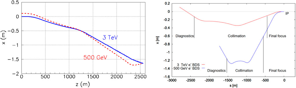
FIGURE 1. Historical footprints of CLIC 3 TeV and 500 GeV beam delivery systems from 2003 [7] (left) and 2010 [69] (right), illustrating the layout changes required due to synchrotron radiation as a function of beam energy.
A second limit set by synchrotron radiation in linear colliders arises in the final quadrupole magnets, where photon emission leads to an energy change, and thereby to a different focal length and increase in the vertical spot size (“Oide effect”) [10], as is illustrated in Figure 2.
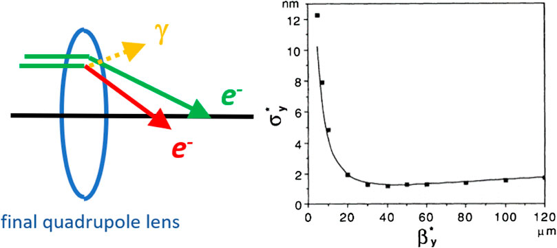
FIGURE 2. Illustration of the Oide effect, where photon emission in the final quadrupole lens results in a minimum possible spot size for an optimized value of
The third, and perhaps most important limitation due to synchrotron radiation at linear colliders relates to the one emitted during the collision in the electromagnetic field of the opposite beam, also called “beamstrahlung”. The strength of the beamstrahlung is characterized by the parameter ϒ, defined as [11,12] ϒ ≡ γB/Bc = (2/3)ℏωc/Ee, with
where α denotes the fine structure constant (α ≈ 1/137), re ≈ 2.8 × 10⁻¹⁵ m the classical electron radius, Nb the bunch populaiton σz the rms bunch length, and
In the classical regime ϒ ≪ 1, and for flat Gaussian beams, the number of photons emitted per beam particle during the collision is [14].
The parameter nγ is important, since it describes the degradation of the luminosity spectrum. Namely, the emission of beamstrahlung photons changes the energy of the emitting electron or positron, and thereby the energy of its later collision. The fraction of the total luminosity Ltot at the target centre-of-mass energy L0 is determined by nγ as [15].
To illustrate this degradation with an example, for CLIC at 380 GeV 60% of the total luminosity lie within 1% of the target energy, while at 3 TeV this fraction decreases to only 34%. Figure 3 presents the respective luminosity spectra [16]. In this way, at TeV energies, e+e− collisions in linear colliders lose their distinct energy precision.
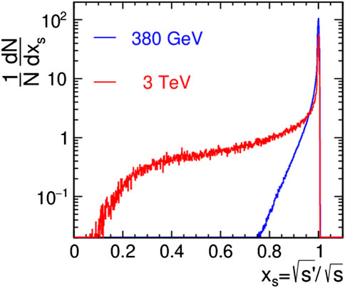
FIGURE 3. Differential luminosity as a function of normalized centre-of-mass energy,
The muon is about 200 times heavier than the electron, which, according to Eq. 1, implies close to 2 × 10⁹ times less radiation at the same energy and bending radius. On the other hand, muon beams have two drawbacks: their production is not trivial, and the muons decay, with a rather short lifetime of only 2.2 μs at rest. In Section 5.2, we will present an innovative approach to the muon collider.
The radiation emission is suppressed at wavelengths larger than
It is noteworthy that classically a uniform time-independent beam does not emit any synchrotron radiation [18,19]. For example, the CERN ISR operated with high-current stationary beams. In the case of such a coasting beam, residual radiation could arise from shot noise or from beam instabilities. The shot noise might be reduced by suitable manipulations—see e.g., [20] — or by stochastic cooling. The shot noise and, therefore, the associated synchrotron radiation can be markedly reduced in case the cooling is so strong as to produce a crystalline beam [21]. Accelerating a “DC” (or near-DC) beam may be accomplished by induction acceleration [22].
The energy reach of hadron colliders is determined by their size and by the magnetic field—see Eq. 3.
All SC hadron storage rings built to date used magnets based on Nb-Ti conductor, for which the maximum reachable magnetic field is 8–9 T, as for the LHC dipole magnets. To go beyond this field level, the High Luminosity LHC (HL-LHC) upgrade foresees the installation of a few tens of higher-field magnets made from Nb3Sn superconductor, with a design peak field of 11–12 T. The FCC-hh is designed with a few 1,000 of Nb3Sn magnets with a higher field of 16 or 17 T, which is close to the maximum field that can be reached with this type of conductor. To achieve even higher fields, high-temperature superconductors are under consideration. At CERN magnets based on REBCO are being developed. In China iron-based superconductor, with a field of up to 24 T, is the material of choice for the SPPC.
The coils of the SC magnets for future hadron colliders must withstand extreme pressure and forces, without any quench and without any degradation in performance. The horizontal forces per quadrant in dipole accelerator magnets approach 10 MN/m for a field of 20 T [23].
As for the bending fields, also for the accelerating systems, superconducting materials have gained widespread use. Superconducting radiofrequency (RF) cavity systems underpin many modern facilities, the latest examples being the European XFEL at DESY Hamburg, the LCLS-II at SLAC, and FRIB in Michigan. Accelerating fields have been increased from a few MV/m to more than 30 MV/m for multicell cavities, and close to twice this value for single cells. Most SC cavities to date have been based on bulk Nb or in Nb-on-Cu cavities. New cavity treatments (nitrogen doping or nitrogen infusion [24]), innovative production methods (chemical vapor deposition [25], high impulse power magnetron sputtering [26]) and new materials, e.g., Nb3Sn [27], as for the magnets, etc. promise further significant advances in performance, by factors of 2–10 in quality factor Q0 and of 2–3 in maximum accelerating gradient. As an example, for Nb3Sn, the theoretical ultimate “superheating” field [28] corresponds to a maximum accelerating gradient of ∼ 100 MV/m, about twice the corresponding value for Nb, while the latter is not far from the currently achieved peak values of about 50 MV/m for Nb cavities [27].
Other advanced accelerating concepts can reach much higher gradients. For example, plasma acceleration routinely achieves fields of 100 GV/m, which is 3,000 times higher than the Nb cavities proposed for the International Linear Collider. The accelerating plasma waves can be driven either by a high-energy charged particle beam or by a laser. Comprehensive concepts have been developed for electron-positron colliders based on either beam-driven [29,30] or laser-driven plasma acceleration [31,32]. Beam quality, pulse-to-pulse stability, and energy efficiency of plasma accelerators [33] are critical issues addressed by ongoing R& D programs. High-energy colliders are arguably the most demanding application of plasma acceleration. Possible ultimate limits of plasma acceleration arise from the scattering of beam particles off plasma nuclei and plasma electrons, and from the emission of betatron radiation [34]. Both of these effects might be partially mitigated by accelerating in a hollow plasma channel. For realizing e+e− colliders, not only electrons but also positrons must be accelerated in the plasma, while preserving the beams’ transverse and longitudinal emittance. For this purpose, more complex plasma excitation schemes may need to be developed, e.g., [35, 36].
Thanks to their higher electron density, even larger gradients can be generated in crystals. The maximum field is given by [37].
with ωp the angular plasma frequency and n0 the electron density. With n0 ≈ 1022 cm−3 to 5 × 1024 cm−3 in a crystal, peak gradients of 10–1000 TV/m would be within reach. Accelerating crystal waves could be excited by X-ray lasers [37].
Several future colliders require unprecedented production rates of positrons (linear colliders) and muons (muon collider), while future circular colliders need positrons at a level already demonstrated, as is illustrated in Figure 4.
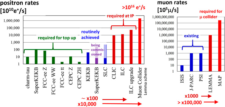
FIGURE 4. Production rates of positrons at dedicated e+e− colliders [68] (left) and of muons at non-collider facilities [70] (right) presently achieved (blue) and required for various future collider projects (red, brown and green). Note the logarithmic scale on the vertical axes.
The present world record positron production rate of about 5 × 10¹² e+ per second was established at the SLC in the 1990s. Even achieving, or reproducing, this SLC rate is not trivial. The SLC target failed after 5 years of operation. For a dedicated failure analysis performed at LANL, the failed SLC positron target was cut into pieces and metallographic studies were carried out to examine the level of deterioration of material properties due to radiation exposure. The hardness of the target material in units of kg/mm2 was found to be decreased by about a factor of 2, over the first 10 mm. However, whether this degradation had been due to radiation damage, work hardening, or temperature cycling could not be clearly resolved.
To push the production rate of e+ and μ′s much beyond the state of the art, a candidate ultimate source of positrons and muons is the Gamma factory [38], which we discuss in the following subsection.
The Gamma factory [38] is based on resonant scattering of laser photons off partially stripped heavy-ion beam in the existing LHC or in the planned FCC-hh. Profiting from two Lorentz boosts, the Gamma factory acts as a high-stability laser-light-frequency converter, with a maximum photon frequency equal to νγ,max = 4γ2νlaser, where γ is the relativistic Lorentz factor of the partially stripped ion beam. This allows the production of intense bursts of gamma rays with photon energies of up to several 100 MeV.
In particular, the Gamma factory can serve as a powerful source of e+ (yielding 1016–1017 e+/s—five orders of magnitude higher than the state of the art), μ (1011–1012/s), π, etc. The positron rate available from the Gamma factory would be sufficient for a LEMMA type muon collider [39,39]. The Gamma factory would also allow for doppler laser cooling of high-energy beams, and, thereby, provide an avenue to a High Luminosity LHC based on laser-cooled isocalar ion beams [41].
The LEMMA scheme for a muon collider is based on the annihilation of positrons with electrons at rest [39]. The cross section for continuum muon pair production e+e− → μ+μ− has a maximum value of about 1 μb at a centre-of-mass energy of ∼0.230 GeV, which corresponds to a positron beam energy of about 45 GeV, exactly as required for the FCC-ee operating as a TeraZ factory and provided by the FCC-ee full-energy booster [42].
Challenges with the LEMMA-type muon production scheme relate to the emittance preservation of muons and muon-generating positrons upon multiple traversals through a target, and the merging of many separate muon bunchlets, due to production by many separate positron bunches or positron bunch passages.
These challenges may potentially be overcome by [43]:
• Operating the FCC-ee booster with a barrier bucket and induction acceleration, so that all positrons of a cycle are merged into one single superbunch [44], instead of
• Sending the positron superbunch from the booster into a plasma target, where, during the passage of the positron superbunch, the electron density is enhanced 100–1,000 fold without any significant density of nuclei, hence with beamstrahlung and Coulomb scattering absent.
Since the positron bunch will be mismatched to the nonlinear plasma channel, filamentation and significant transverse emittance growth may result [43].
For a typical initial plasma electron density of ne = 1023 m−3, and assuming a density enhancement by a factor of 1,000, due to the electron pinch in the positive electric field of the positron beam, the positrons annihilate into muon pairs at a rate of 10–8 m−1.
As described in the CDR [45], the FCC-ee booster can accelerate 3.5 × 10¹⁴ positrons every 50 s. Using the much more powerful Gamma Factory positron source, with a rate of 1016–1017 e+ s−1 [38], and injecting into the booster during one or a few seconds, of order 1017 e+ can be accumulated, at the booster injection energy of ∼20 GeV. The positrons can be captured into a single barrier RF bucket, with a final length of
Accelerating the long positron superbunch containing 1017 e+ by 25 GeV, from 20 to 45 GeV, requires a total energy of 0.4 GJ, or, if accelerated over 2 s, about 200 MW of RF power. This translates into an induction acceleration voltage of ∼2 MV per turn, which is three orders of magnitude higher than the induction voltage of the KEK digital accelerator [46], but about 10 times lower than the induction RF voltage produced at the LANL DARHT-II [47], at much higher or lower repetition rate, respectively. On the ramp and at top energy, the full bunch length lb can conceivably be compressed to the assumed lb ≈ 5 m, by squeezing the gap of the barrier bucket (which requires substantially more voltage for the barrier RF system)—also see [21,46]. Tentative parameters of the positron superbunch are compiled in Table 1. We assume that the booster ring runs near the coupling resonance so that the emittance is shared between the two transverse planes.

TABLE 1. Tentative parameters of the positron superbunch sent onto the plasma target.
When the accelerated and compressed positron bunch is sent into the plasma channel, we consider that the plasma electron distribution quickly acquires a nearly stationary shape, while any remaining plasma ions are slowly repelled away from the positron beam. In the stationary phase, the electron distribution approaches a shape that mimics the one of the positron beam, with a density
so as to neutralize the electric field. With an average rms size of σ⊥ ≈ 10 μm, we obtain
In particular, once the electron distribution is nearly stationary, the longitudinal fields inside the plasma can be neglected. The resulting transverse emittance of the produced muons can be optimized by adjusting positron beam parameters and the optical functions at the entrance to the plasma [43]. In addition, a phase rotation (bunch compression) of the muons may be required, since the initial bunch length
Overall, the described scheme, sketched in Figure 5, would produce about 1012 muon pairs per cycle, with a cycle length of order 3 s. Even at an energy of 50 TeV, the muons would decay with a lifetime of only 1.1 s. This kind of cycle/lifetime ratio of about 3:1 might still be considered acceptable. On the other hand, for collision at a muon beam energy of seven TeV in the existing LHC ring, the muon lifetime would be only 0.15 s, and the scheme would be considerably more challenging.
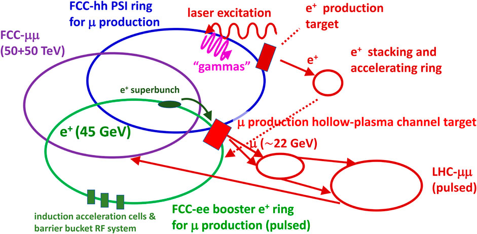
FIGURE 5. Concept of a 100 TeV μ collider based on FCC-hh and FCC-ee. In one of the FCC-hh rings, partially stripped heavy ions are collided with a pulsed laser to generate intense high-energy gamma rays that are converted into positrons, which are accumulated, then accelerated, and injected into a barrier bucket in the FCC-ee booster ring. The resulting superbunch is brought to a positron energy of 45 GeV, with induction acceleration, where the superbunch is extracted and sent into a plasma target, leading to a plasma electron density enhancement and, thereby, amplified annihilation into muon pairs. The muons are accelerated in a modifed SPS and LHC, to be finally injected and accelerated in the second FCC-hh collider ring. This is a modified version of the scheme presented in Ref. [40].
Radiofrequency (RF) systems are used to keep a charged particle beam bunched, and to feed energy to the beam, be it for purposes of acceleration or to compensate for the energy lost due to synchrotron radiation. In superconducting continuous-wave RF cavities, almost no power is lost to the cavity wall and all RF power entering the cavity can be transferred to the beam highly efficiently. Then, in the overall power budget, the RF power source is the most inefficient element. For RF frequencies above about 400 MHz, and for high power applications, historically klystrons have been the RF power source of choice on particle accelerators.
It is most remarkable that about 80 years after the invention of the klystron by the Varian brothers, a revolution in klystron technology is underway. Using advanced bunching techniques, it is expected that the klystron efficiency can be raised from the present 50–60% level to about 90%, which would translate into a significant energy saving [48]. Prototypes of such novel highly-efficient klystrons are being manufactured both by CERN, in collaboration with industry, for FCC, CLIC and ILC, and, in China, for the CEPC project.
In parallel, the efficiency of alternative RF power sources, such as inductive output tubes or solid-state amplifiers [49], is also being improved.
While at present the RF power sources are the dominant contributors to overall grid-to-beam power transmission inefficiency, a few percent additional losses each occur in the electrical network between utility high-voltage interconnect point and RF power source, and in the wave guides and couplers feeding the generated RF power into the accelerating cavities, respectively.
For high fields, superconducting magnets are most efficient, as no energy is lost, and electric power is mostly required for the cryogenic system. For lower fields, up to of order 1 T, permanent magnets are most energy efficient. An example is the Fermilab Recycler Ring [50], which was built almost entirely from permanent magnets. Even adjustable permanent magnets have been designed and built for applications at light sources, colliders, and plasma accelerators [51]. Other ingenious solutions for energy saving can be found, depending on the respective application. For example, for the FCC-ee double-ring collider, twin dipole and quadrupole magnets at low field (of order 0.05 T, for the dipoles) have been designed [52], which promise a significant power reduction compared with the magnets of comparable fields at earlier colliders.
Recovering the energy of the spent beam after one or several collisions is another effective measure to improve overall energy efficiency, if a significant fraction of the overall electric power is stored in the beam, as typically is the case for beams accelerated in superconducting linacs [53].
A comparison of ERL-based colliders proposed half a century ago with several recent concepts is presented in Table 2. The main differences between proposals from the 1970s and today are the collision of flat beams instead of round beams, much smaller (vertical) beam sizes, combined with higher beam current, yielding, on paper, of order ∼10,000 times higher luminosity than the proposals from half a century ago.
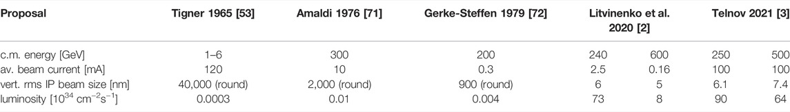
TABLE 2. A comparison of ERL-based colliders proposed in the 1960s [53] and 1970s [71,72], and in the recent period 2019–2021 [3,2].
Also minimisation of beam loss can improve the energy efficiency of accelerators, such as ERLs. For proposed future higher-energy facilities, machine protection and beam collimation systems become ever more challenging due to their unprecedented beam power or stored energy. For example, the FCC-hh design features a stored beam energy of 8.3 GJ [54], which is more than a factor 20 higher than for the LHC.
Storage rings constructed as high energy physics colliders could also serve for other intriguing applications. In this section, we mention a few examples.
Large circular storage rings like the FCC-ee, and even the FCC-hh, can serve as ultimate storage-ring light sources, with diffraction limited emittances down to photon wavelengths of
For FCC-ee the geometric emittance ɛx, of the collider or of the full-energy booster, scales as γ2, and the lowest value of ɛx ≈ 50 pm is reached at the injection energy of 20 GeV, resulting in λmin,ee ≈ 650 pm. With a beam current of 1.5 A or higher, this could represent a formidable light source. Conversely, for FCC-hh the normalized proton beam emittance γɛx shrinks during proton beam storage at 50 TeV to
The FCC-ee ring emittance could be further reduced by factors of 10–100 through the addiition of damping wigglers, pushing the accessible wavelength into the 10 pm regime.
A more detailed study of synchrotron light produced by such low-emittance FCC-ee beams passing through realistic undulator configurations has been performed recently [55]. For hadron storage rings, their use as a light source was discussed in the past, e.g., for the Superconducting Super Collider (SSC) [56].
In addition, also Free Electron Lasers (FELs) based on ERLs designed for high-energy physics colliders can offer outstanding performance in terms of average brightness, and in their wavelength reach down into the few picometre range [57], e.g., in the case of the LHeC-ERL based FEL, with a beam current of ∼20 mA.
Various approaches have been suggested for using beams in a storage ring for the detection of gravitational waves [58–61] including the construction of special optics with regions of extremely high beta functions that would serve as gravitational wave antennae [61,62]. Exploration of such possibilities continues.
With advanced cooling and manipulation schemes, storage rings might eventually be used as quantum computers [63,63]. Indeed, combining the storage rings of charged particles with the linear ion traps used for quantum computing and mass spectrometry would enable a large leap in the number of ions serving as qubits in the quantum computing. Such an approach holds the promise of significant advances in general quantum calculations and, especially, in simulations of complex quantum systems.
To reach the Planck scale of 1028 eV, linear or circular colliders would need to have a size of order 1010 m, which is about a 10th of the distance between the Earth and the Sun, if operated close to the Schwinger critical field [65,66].
Following the FCC a possible next or next-next step in this direction could be a circular collider on the Moon (CCM) [67]. With a circumference of about 11 Mm, a centre-of-mass energy of about 14 PeV (1,000 times the energy of the LHC), based on 6 × 10⁵ dipoles with 20 T field, either ReBCO, requiring ∼7–13 ktons of rare-earth elements, or iron-based superconductor (IBS), requiring of order a million tons of IBS [67]. Many of the raw materials required to construct machine, injector complex, detectors, and facilities can potentially be sourced directly on the Moon. The 11,000-km tunnel should be constructed a few 10–100 m under lunar surface to avoid lunar day-night temperature variations, cosmic radiation damage, and meteoroid strikes. A “Dyson band” or “Dyson belt” could be used to continuously collect Sun power. Operating the collider would require the equivalent of 0.1% of the Sun power incident on Moon surface [67].
Particle colliders boast an impressive 70 years long history, with dramatic improvements in performance, and they will also be the cornerstone for a long and exciting future in high-energy physics. Future colliders should heed the lessons from the previous generations of colliders, like LEP, SLC, KEKB, PEP-II, LHC, and SuperKEKB.
Present collider-accelerator R&D trends include the development of more powerful positron sources; the widespread application of energy recovery; “nanobeam” handling—with stabilisation, positioning, and tuning; the polarization control at the 0.1% level; monochromatization; the use of machine learning and artificial intelligence, e.g., for automated design and for accelerator operation; and the introduction of novel uses such as for probing gravity or developing high-throughput quantum computing; plus, last not least, bringing advanced acceleration schemes to maturity.
Considering the desired higher intensity and energy for future machines, a major challenge will be to make the future colliders truly “green,” that is energy-efficient and sustainable. In this context, suppressing synchrotron radiation or mitigating its impact becomes a key objective for the long term. Concerning the near term, it is important to observe that the Future Circular lepton Collider, FCC-ee, is the most sustainable of all the proposed Higgs and electroweak factory proposals, in that it implies the lowest energy consumption for a given value of total integrated luminosity [68], over the collision energy range from 90 to 365 GeV.
For the Future Circular Collider (FCC) effort, the next concrete steps encompass a specific local and regional implementation scenario worked out in collaboration with host states, machine design optimization, physics studies and technology R&D, performed via a global collaboration and supported by the EC H2020 FCC Innovation Study, to prove the FCC feasibility by 2025/26.
The work reported reflects half a century of accelerator R&D and progress with charged particle colliders. The author confirms being the sole author of this review article, which cites relevant contributions by others, and has approved it for publication.
This work was supported, in parts, by funding from the European Union’s Horizon 2020 Research and Innovation programme under Grant Agreement No. 101004730 (iFAST).
The author declares that the research was conducted in the absence of any commercial or financial relationships that could be construed as a potential conflict of interest.
All claims expressed in this article are solely those of the authors and do not necessarily represent those of their affiliated organizations, or those of the publisher, the editors and the reviewers. Any product that may be evaluated in this article, or claim that may be made by its manufacturer, is not guaranteed or endorsed by the publisher.
The author would like to thank R. Aßmann, M. Benedikt, G. Franchetti, K. Oide and many other colleagues for helpful discussions.
1. Abelleira Fernandez JL, Adolphsen C, Akay AN, Aksakal H, Albacete JL, Alekhin S, et al. A Large Hadron Electron Collider at CERN: Report on the Physics and Design Concepts for Machine and Detector. J. Phys. G: Nucl. Part. Phys (2012) 39:075001. doi:10.1088/0954-3899/39/7/075001
2. Litvinenko VN, Roser T, Chamizo-Llatas M. High-Energy High-Luminosity e+e− Collider Using Energy-Recovery Linacs. Phys Lett B (2020) 804:135394. doi:10.1016/j.physletb.2020.135394
3. Telnov VI. A High-Luminosity Superconducting Twin e+e− Linear Collider with Energy Recovery. JINST (2021) 16:P12025. doi:10.1088/1748-0221/16/12/P12025
4. Richter B. Very High Energy Electron-Positron Colliding Beams for the Study of Weak Interactions. Nucl Instr Methods (1976) 136:47–60. doi:10.1016/0029-554X(76)90396-7
5. Myers S. FCC: Building on the Shoulders of Giants. Eur Phys J Plus (2021) 136:1076. doi:10.1140/epjp/s13360-021-02056-w
6. Oide K. A Final Focus System for Flat-Beam Linear Colliders. Nucl Instr Methods Phys Res Section A: Acc Spectrometers, Detectors Associated Equipment (1989) 276:427–32. doi:10.1016/0168-9002(89)90567-6
7. Aleksa M, Assmann RW, Burkhardt H, Jeanneret JB, Redaelli S, Risselada T, et al. CLIC Beam Delivery System. CERN Rep CLIC-Note-551 (2003).
8. Zimmermann F. Magnet Alignment Tolerances in the 1994 SLC Final Focus System. SLAC SLC Collider Note SLAC-CN-398 (1994).
10. Oide K. Synchrotron-Radiation Limit on the Focusing of Electron Beams. Phys Rev Lett (1988) 61:1713–5. doi:10.1103/PhysRevLett.61.1713
11. Yokoya K. Quantum Correction to Beamstrahlung Due to the Finite Number of Photons. Nucl Instr Methods Phys Res Section A: Acc Spectrometers, Detectors Associated Equipment (1986) 251:1–16. doi:10.1016/0168-9002(86)91144-7
12. Yokoya K, Chen P. Beam-Beam Phenomena in Linear Colliders. Lect Notes Phys (1992) 400:415–45. doi:10.1007/3-540-55250-2_37
13. Sands M. The Physics of Electron Storage Rings: An Introduction. Conf Proc C (1969) 6906161:257–411.
14. Chen P. Review of Linear Collider Beam-Beam Interaction. AIP Conf Proc (1989) 184:633–79. doi:10.1063/1.38047
15. Chen P. Differential Luminosity Under Multiphoton Beamstrahlung. Phys Rev D (1992) 46:1186–91. doi:10.1103/PhysRevD.46.1186
16. Abramowicz H, Alipour Tehrani N, Arominski D, Benhammou Y, Benoit M, Blaising JJ, et al. Top-Quark Physics at the CLIC Electron-Positron Linear Collider. J High Energ Phys (2018) 2019:3. doi:10.1007/JHEP11(2019)003
17. Warnock RL. Shielded Coherent Synchrotron Radiation and its Effect on Very Short Bunches. In: 4th Advanced ICFA Beam Dynamics Workshop: Collective Effects in Short Bunches. SLAC Publication SLAC-PUB-5375 (1990).
18. Schwinger J. On Radiation by Electrons in a Betatron. Quantum Legacy (1945) 1945:307–31. doi:10.2172/1195620
19. Arzimovitch L, Pomeranchuk I. The Radiation of Fast Electrons in the Magnetic Field. J Phys (Moscow) (1945) 9:267.
20. Ratner D, Stupakov G. Observation of Shot Noise Suppression at Optical Wavelengths in a Relativistic Electron Beam. Phys Rev Lett (2012) 109:034801. doi:10.1103/PhysRevLett.109.034801
21. Primack H, Blümel R. Synchrotron Radiation of Crystallized Beams. Phys Rev E (1999) 60:957–67. doi:10.1103/PhysRevE.60.957
22. Takayama K, Briggs RJ, (editors). Induction Accelerators. Particle Acceleration and Detection. Heidelberg, Germany: Springer (2011). doi:10.1007/978-3-642-13917-8
23. Bottura L. High Field Magnets. In: Future Collider Forum: 1st Workshop, DESY; 6–8 October, 2021 (2021).
24. Dhakal P. Nitrogen Doping and Infusion in SRF Cavities: A Review. Phys Open (2020) 5:100034. doi:10.1016/j.physo.2020.100034
25. Ge M, Arrieta V, Gruber T, Kaufman JJ, Liepe M, Maniscalco JT, et al. CVD Coated Copper Substrate SRF Cavity Research at Cornell University. In: Proc. 19th Int. Conf. RF Superconductivity (SRF’19). Geneva: JACoW Publishing (2019). p. 381–6. doi:10.18429/JACoW-SRF2019-TUFUB8
26. Sayeed M, Elsayed-Ali H, Eremeev GV, Kelley MJ, Reece CE, Pudasaini U. Magnetron Sputtering of Nb3Sn for SRF Cavities. In: Proc. 9th Int. Particle Accelerator Conf. (IPAC’18). Geneva: JACoW Publishing (2018). p. 3946–9. doi:10.18429/JACoW-IPAC2018-THPAL129
27. Posen S, Liepe M, Eremeev G, Pudasaini U, Reece CE. Nb3Sn Superconducting Radiofrequency Cavities: A Maturing Technology for Particle Accelerators and Detectors. In: 2022 Snowmass Summer Study (2022).
28. Padamsee H, Shepard KW, Sundelin R. Physics and Accelerator Applications of Rf Superconductivity. Annu Rev Nucl Part Sci (1993) 43:635–86. doi:10.1146/annurev.ns.43.120193.003223
29. Adli E, Delahaye J-P, Gessner SJ, Hogan MJ, Raubenheimer T, An W, et al. A Beam Driven Plasma-Wakefield Linear Collider: From Higgs Factory to Multi-TeV. arXiv 1308.1145 (2013). doi:10.2172/1074154
30. Chen JBB, Schulte D, Adli E. e+e− Beam-Beam Parameter Study for a TeV-Scale PWFA Linear Collider. arXiv 2009.13672 (2021).
31. Leemans W, Esarey E. Laser-Driven Plasma-Wave Electron Accelerators. Phys Today (2009) 62:44–9. doi:10.1063/1.3099645
32. Schroeder CB, Benedetti C, Esarey E, Leemans WP. Laser-Plasma-Based Linear Collider Using Hollow Plasma Channels. Nucl Instr Methods Phys Res Section A: Acc Spectrometers, Detectors Associated Equipment (2016) 829:113–6. doi:10.1016/j.nima.2016.03.001
33. Lebedev V, Burov A, Nagaitsev S. Efficiency versus Instability in Plasma Accelerators. Phys Rev Accel Beams (2017) 20:121301. doi:10.1103/PhysRevAccelBeams.20.121301
34. Zimmermann F. Possible Limits of Plasma Linear Colliders. J Phys Conf Ser (2017) 874:012030. doi:10.1088/1742-6596/874/1/012030
35. Xu ZY, Xiao CF, Lu HY, Hu RH, Yu JQ, Gong Z, et al. New Injection and Acceleration Scheme of Positrons in the Laser-Plasma Bubble Regime. Phys Rev Accel Beams (2020) 23:091301. doi:10.1103/PhysRevAccelBeams.23.091301
36. Hue CS, Cao GJ, Andriyash IA, Knetsch A, Hogan MJ, Adli E, et al. Efficiency and Beam Quality for Positron Acceleration in Loaded Plasma Wakefields. Phys Rev Res (2021) 3:043063. doi:10.1103/PhysRevResearch.3.043063
37. Shiltsev VD. High-Energy Particle Colliders: Past 20 years, Next 20 years, and Beyond. Phys.-Usp. (2012) 55:965–76. doi:10.3367/UFNe.0182.201210d.1033
39. Antonelli M, Boscolo M, Di Nardo R, Raimondi P. Novel Proposal for a Low Emittance Muon Beam Using Positron Beam on Target. Nucl Instr Methods Phys Res Section A: Acc Spectrometers, Detectors Associated Equipment (2016) 807:101–7. doi:10.1016/j.nima.2015.10.097
40. Zimmermann F. LHC/FCC-Based Muon Colliders. J Phys Conf Ser (2018) 1067:022017. doi:10.1088/1742-6596/1067/2/022017
41. Krasny M, Petrenko A, Placzek W. The Gamma Factory Path to High-Luminosity LHC with Isoscalar Beams. PoS (2021) ICHEP2020:690. doi:10.22323/1.390.0690
42. Benedikt M, Zimmermann F. Future Circular Collider: Integrated Programme and Feasibility Study. Submitted Front Phys (2022).
43. Zimmermann F, Latina A, Blondel A, Antonelli M, Boscolo M. Muon Collider Based on Gamma Factory, FCC-Ee and Plasma Target (2022). Submitted to IPAC’22.
45.The FCC Collaboration. FCC-ee: The Lepton Collider. Eur Phys J Spec Top (2019) 228:261. doi:10.1140/epjst/e2019-900045-4
46. Takayama K, Yoshimoto T, Barata M, Wah LK, Xingguang L, Iwashita T, et al. Induction Acceleration of Heavy Ions in the KEK Digital Accelerator: Demonstration of a Fast-Cycling Induction Synchrotron. Phys Rev ST Accel Beams (2014) 17:010101. doi:10.1103/PhysRevSTAB.17.010101
47. Nielsen K, Barraza J, Kang M, Bieniosek F, Chow K, Fawley W, et al. Upgrades to the DARHT Second Axis Induction Cells. Conf Proc C (2007) 070625:2385. doi:10.1109/PAC.2007.4441258
48. Baikov AY, Marrelli C, Syratchev I. Toward High-Power Klystrons with RF Power Conversion Efficiency on the Order of 90. IEEE Trans Electron Dev (2015) 62:3406–12. doi:10.1109/TED.2015.2464096
49. Barov N, Chang X, Newsham DJ, Wu D. Development of the Energy-Efficient Solid State RF Power Source for the Jefferson Laboratory CEBAF Linac. Conf Proc C (2012) 1205201:3455–7.
50. Volk JT. Experiences with Permanent Magnets at the Fermilab Recycler Ring. J Inst (2011) 6:T08003. doi:10.1088/1748-0221/6/08/t08003
51. Shepherd B. Permanent Magnets for Accelerators. JACoW (2020) IPAC2020:MOVIRO05. doi:10.18429/JACoW-IPAC2020-MOVIRO05
52. Milanese A. Efficient Twin Aperture Magnets for the Future Circular e+/e− Collider. Phys Rev Accel Beams (2016) 19:112401. doi:10.1103/PhysRevAccelBeams.19.112401
53. Tigner M. A Possible Apparatus for Electron Clashing-Beam Experiments. Nuovo Cim (1965) 37:1228–31. doi:10.1007/BF02773204
54.The FCC Collaboration. FCC-hh: The Hadron Collider. Eur Phys J Spec Top (2019) 228:755. doi:10.1140/epjst/e2019-900087-0
55. Casalbuoni S, Benedikt M, Doser M, Zimmermann F. First Thoughts on the Synergetic Use of the FCC-ee Collider and its Injector Complex for Photon Science and Other Applications. CERN/FCC Intern Note (2020).
56. Dutt SK. Synchrotron Radiation from Protons. In: Workshop on 4th Generation Light Sources (1992). SSC Pub SSCL-Preprint-182.
57. Nergiz Z, Mirian NS, Aksoy A, Zhou D, Zimmermann F, Aksakal H. Bright Ångstrom and Picometer Free Electron Laser Based on the Large Hadron Electron Collider Energy Recovery Linac. Phys Rev Accel Beams (2021) 24:100701. doi:10.1103/PhysRevAccelBeams.24.100701
58. Zer-Zion D. Possible Detection of High Frequency Gravitational Waves in Storage Rings: Speculation on Future Applications. Astropart Phys (2000) 14(3):239–43.
59. van Holten JW. Cyclotron Motion in a Gravitational Wave Background (1999). doi:10.48550/arXiv.gr-qc/9906117
60. Rao S, Brüggen M, Liske J. Detection of Gravitational Waves in Circular Particle Accelerators. Phys Rev D (2020) 102:122006. doi:10.1103/PhysRevD.102.122006
61. Berlin A, Brüggen M, Buchmueller O, Chen P, D'Agnolo RT, Deng R, et al. Storage Rings and Gravitational Waves: Summary and Outlook. In: ARIES WP6 Workshop: Storage Rings and Gravitational Waves (2021). arXiv 2105.00992.
62. Oide K. Response of a Storage-Ring Beam to a Gravitational Wave - Preliminary Considerations (2021). Presented at ARIES SRGW2021 Workshop.
63. Brown KA, Roser T. Towards Storage Rings as Quantum Computers. Phys Rev Accel Beams (2020) 23:054701. doi:10.1103/PhysRevAccelBeams.23.054701
64. Shaftan T, Blinov BB. Cold Ion Beam in a Storage Ring as a Platform for Large-Scale Quantum Computers and Simulators: Challenges and Directions for Research and Development. Phys Rev Accel Beams (2021) 24:094701. doi:10.1103/PhysRevAccelBeams.24.094701
65. Chen P, Noble RJ. Crystal Channel Collider: Ultra-High Energy and Luminosity in the Next Century. AIP Conf Proc (1997) 398:273–85. doi:10.1063/1.53055
66. Zimmermann F. Future Colliders for Particle Physics-“Big and Small”. Nucl Instr Methods Phys Res Section A: Acc Spectrometers, Detectors Associated Equipment (2018) 909:33–7. doi:10.1016/j.nima.2018.01.034
67. Beacham J, Zimmermann F. A Very High Energy Hadron Collider on the Moon. New J Phys (2022) 24:023029. doi:10.1088/1367-2630/ac4921
68. Benedikt M, Blondel A, Janot P, Mangano M, Zimmermann F. Future Circular Colliders Succeeding the LHC. Nat Phys (2020) 16:402–7. doi:10.1038/s41567-020-0856-2
69. Zamudio G, Tomas R. Optimization of the CLIC 500 GeV Final Focus System and Design if a New 3 TeV Final Focus System with L*=6.0 M. Geneva: Tech. Rep., CERN (2010).
70. Zimmermann F. Shaping the Future of High-Energy Physics - Accelerators. CERN Acad Train Lectures (2021).
71. Amaldi U. A Possible Scheme to Obtain e-e- and e+e- Collisions at Energies of Hundreds of GeV. Phys Lett B (1976) 61:313–5. doi:10.1016/0370-2693(76)90157-X
Keywords: hadron collider, lepton collider, accelerator R&D, future circular collider, gamma factory, muon collider, linear collider, synchrotron radiation
Citation: Zimmermann F (2022) Accelerator Technology and Beam Physics of Future Colliders. Front. Phys. 10:888395. doi: 10.3389/fphy.2022.888395
Received: 02 March 2022; Accepted: 05 April 2022;
Published: 23 May 2022.
Edited by:
Alessandro Tricoli, Brookhaven National Laboratory (DOE), United StatesReviewed by:
Alexander Valishev, Fermi National Accelerator Laboratory (DOE), United StatesCopyright © 2022 Zimmermann. This is an open-access article distributed under the terms of the Creative Commons Attribution License (CC BY). The use, distribution or reproduction in other forums is permitted, provided the original author(s) and the copyright owner(s) are credited and that the original publication in this journal is cited, in accordance with accepted academic practice. No use, distribution or reproduction is permitted which does not comply with these terms.
*Correspondence: Frank Zimmermann, ZnJhbmsuemltbWVybWFubkBjZXJuLmNo
Disclaimer: All claims expressed in this article are solely those of the authors and do not necessarily represent those of their affiliated organizations, or those of the publisher, the editors and the reviewers. Any product that may be evaluated in this article or claim that may be made by its manufacturer is not guaranteed or endorsed by the publisher.
Research integrity at Frontiers
Learn more about the work of our research integrity team to safeguard the quality of each article we publish.