 Jun Xiao
 Geer Teni2
95% of researchers rate our articles as excellent or good
Learn more about the work of our research integrity team to safeguard the quality of each article we publish.
Find out more
ORIGINAL RESEARCH article
Front. Phys. , 05 April 2022
Sec. Optics and Photonics
Volume 10 - 2022 | https://doi.org/10.3389/fphy.2022.880606
This article is part of the Research Topic Plasmonic Metamaterials and Electromagnetic Devices View all 20 articles
This article presents a dual-polarized corrugated horn antenna incorporated a turnstile orthomode transducer (OMT) covering the full Ka-band (26.5–40 GHz). A three-stepped cylindrical tuning stub scattering element is designed in the turnstile junction to combine/split the two linearly polarized waves with high isolation. The proposed turnstile OMT shows a good simulated return loss better than 20 dB and a high isolation higher than 57 dB within the whole Ka-band. Then, a corrugated horn antenna with five-stage choke rings is designed. Finally, the proposed horn antenna incorporated in the turnstile OMT is fabricated and measured. The measured impedance bandwidth for |S11/22|≤ −15 dB is 50.7% from 25 to 42 GHz. The measured peak gain is 11.9 dBi. The proposed antenna system is a promising candidate for the 5G millimeter-wave applications.
Recently, millimeter-wave (MMW) devices such as antennas [1], filters [2], etc., have attracted much attention from researchers. Reflector antennas have been widely utilized in many fields such as radar, radio astronomy, satellite communications due to the advantages of high gain. As a kind of feed source of the MMW reflector antennas, MMW horn antennas have been widely studied [3–5]. Corrugated horn antennas are one of the most popular feed antennas due to their advantages such as low cross-polarization, symmetrical radiation patterns in two orthogonal planes, and low sidelobe level [6–10]. On the other hand, we are faced with challenges in channel capacity limitations in communication systems. Orbital angular momentum (OAM) [11, 12] and dual-polarization [13] technologies have been proposed to increase the communication capacity. To realize dual-polarized horn antennas, dual-polarized quad-ridged horn antennas or linearly polarized horn antennas integrated with an orthomode transducer (OMT) have been reported. However, the quad-ridged horn antennas have the disadvantages such as high cross-polarization levels and unsymmetrical radiation patterns [14–16]. The OMT can combine or split the waves with two orthogonal polarizations simultaneously. In general, a three-port OMT is made up of a common port and two independent ports with high isolation between each other. Boifot OMT [17–20] and turnstile junction OMT [21–25] are the two kinds of widely used OMTs with wideband characteristics. Compared with the Boifot OMTs, the turnstile junction OMTs can achieve wide impedance bandwidth without pins or septums.
In this article, a dual-polarized corrugated horn antenna using turnstile OMT operating within 24–42 GHz is presented. The turnstile OMT can realize dual-linear polarization and provide high isolation. A corrugated horn antenna with five-stage choke rings is designed as the radiator. The fabricated horn antenna incorporated a turnstile OMT exhibits a 50.7% measured −15 dB impedance bandwidth and an 11.9 dBi measured maximum gain. The measured isolations between the two orthogonal polarizations are lower than -40 dB within the bandwidth.
As a key component of the turnstile OMT, the turnstile junction is designed first. The internal view of the proposed turnstile junction is shown in Figure 1. The turnstile junction is made up of a circular waveguide (port 1), a three-stepped cylindrical tuning stub, and four rectangular waveguide outputs (ports 2–5). The input waves with two orthogonal polarization directions from port 1 can be separated into two linearly polarized waves. The design of the scattering element is critical to the overall performance of the turnstile junction. A four-stepped cylindrical tuning stub has been designed in a turnstile junction achieving 40% bandwidth (10–15 GHz) [21]. According to [21], the impedance bandwidth of a turnstile junction can be increased by increasing the number of steps of the multi-stepped cylindrical scattering element. However, the larger the number of steps, the larger the volume of the turnstile OMT. Moreover, the top metallic cylinder tends to be thinner when the number of steps increases, which may cause larger mechanical errors, especially at millimeter-wave frequency bands. Then, a tradeoff is made between the impedance bandwidth and the number of the steps: a three-stepped cylindrical tuning stub is adopted as the scattering element. Four rectangular stubs are placed in the four corners to improve impedance matching. The detailed dimensions of the three-stepped cylindrical tuning stub are as follows (in mm): D1 = 0.73, D2 = 2.5, D3 = 6.2, h1 = 3.9, h2 = 2.1, h3 = 0.65.
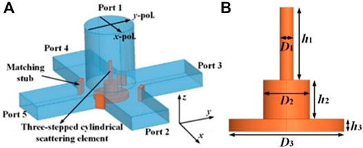
FIGURE 1. Geometry of turnstile junction. (A) Internal view. (B) Three-stepped cylindrical scattering element.
The simulated results of the turnstile junction are shown in Figure 2. The two |S11| curves related to two orthogonal polarization directions are almost the same with each other. They are both almost lower than −20 dB within the bandwidth from 24 to 42 GHz. As shown in Figure 2B, the E-field distributions simulated results indicate that good isolation has been achieved between two input waves with two orthogonal directions, respectively. Figure 2C shows how the TE11 mode input wave in the circular waveguide is converted to two ways of TE10 mode wave.
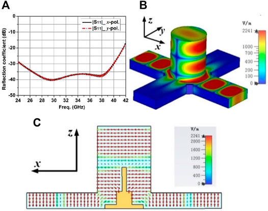
FIGURE 2. Simulated results of the proposed turnstile junction. (A) Reflection coefficient. (B) E-field distribution in the turnstile junction at 35 GHz. (C) Section view of the E-field distribution (35 GHz) inside the turnstile junction.
Based on the above design, a turnstile OMT is designed, as shown in Figure 3. The proposed turnstile OMT includes a turnstile junction, two Y-shaped junctions, a common circular waveguide port (port 3), and two rectangular waveguide ports (port 1 and port 2, respectively). Thanks to the scattering element of turnstile junction, or the three-stepped cylindrical tuning stub, the wave from port 3 with two orthogonal polarization directions can be separated into two linearly polarized waves, which are sent to port 1 and port 2, respectively. Waves separated by the turnstile junction will be routed through 180° E-plane two-stepped bends. Then, power combinations will be carried out through the Y-shaped junctions. The simulated results of the proposed OMT are shown in Figure 3B. The simulated |S11| and |S22| are both lower than −20 dB within the bandwidth from 24 to 41.6 GHz. The proposed design shows high isolation between ports 1 and 2. The simulated |S21| is lower than −57 dB within the bandwidth from 24 to 42 GHz.
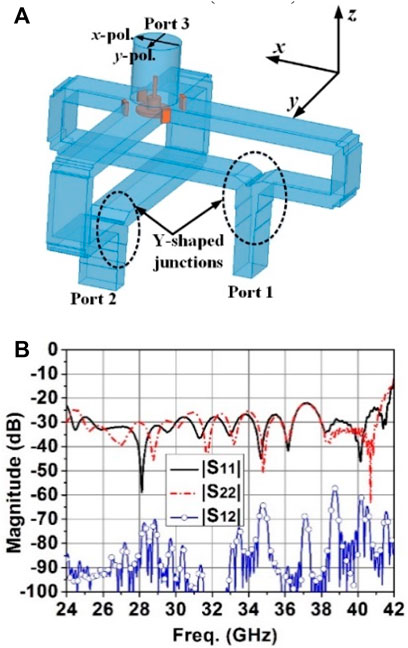
FIGURE 3. (A) Internal view of the turnstile OMT. (B) Simulated results of the turnstile OMT.
The proposed choke ring horn antenna is shown in Figure 4. The five-stage choke rings are fed by a circular waveguide which is excited by dominant TE11 mode waves. According to the waveguide theory, TEmn and TMmn mode waves will be excited in the choke rings. The depth of each choke should be λ/4 to λ/2 to get equal beam widths, low cross-polarization levels, and low back radiation. To attain broadband impedance and radiation pattern bandwidths covering 26–40 GHz, the five chokes are designed and optimized as different depths. The detailed dimensions of the choke ring horn antenna are as follows (in mm): h1 = 4.97, h2 = 5.59, h3 = 2.87, h4 = 3.26, h5 = 2.61, h6 = 2.61, h7 = 3.95, h8 = 3.2, h9 = 2.71, h10 = 2.84. W1 = 1.87, W2 = 2.14, W3 = 2.26, W4 = 2.18, W5 = 1, W6 = 8.6, W7 = 9.6.
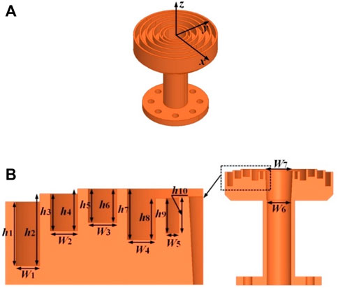
FIGURE 4. Simulation model of the proposed corrugated horn antenna. (A) 3-D view. (B) Section view.
Under these conditions, the electric fields over the radiation aperture will decay along the radius axial direction. The simulated electric field distributions in yoz-plane at z = 1 mm for different frequencies are shown in Figure 5. It is observed that the E-fields are similar to Gaussian distribution which leads to rotationally symmetric radiation patterns. The simulated results of the proposed choke ring horn antenna are shown in Figures 6, 7. The |S11| is less than −15 dB in 26–40 GHz frequency band. The maximum gain is 12.5 dBi. Good rotationally symmetric radiation patterns have been observed within the bandwidth.
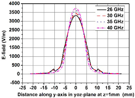
FIGURE 5. Simulated electric field distributions in yoz-plane at z = 1 mm for different frequencies.
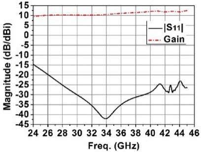
FIGURE 6. Simulated results of the proposed corrugated horn antenna.
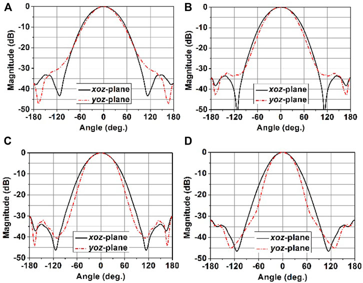
FIGURE 7. Simulated radiation patterns of the proposed corrugated horn antenna element at (A) 26 GHz. (B) 30 GHz. (C) 35 GHz. (D) 40 GHz.
Based on the designs presented above, the co-simulations of the OMT and choke ring horn antenna are carried out. The simulated model is shown in Figure 8A. Then, an OMT and a horn antenna are fabricated separately. The OMT is incorporated into a box-type flange. The fabricated dual-polarized antenna system after assembly is shown in Figure 8C. The measured results of port matching and port isolation are shown in Figure 9. The measured −15 dB impedance bandwidths (|S11/22| ≤ −15 dB) are both 50.7% covering from 25 to 42 GHz at two ports, respectively. The simulated and measured isolations between two ports are larger than 85 and 40 dB within the bandwidth of 25–42 GHz, respectively. The measured maximum gain is 11.9 dBi at 42 GHz while the simulated one is 12.4 dBi at 41 GHz. The measured gains are all larger than 9.9 dBi within the bandwidth. The measured radiation efficiency can be calculated by comparing the simulated directivity and the measured gain. Then the measured radiation efficiency of the horn antenna (with OMT) is 90.2% at 36 GHz. The measured aperture efficiency is 78.6% at 36 GHz. The simulated and measured radiation patterns for port 1 at frequencies of 26, 30, 35, and 40 GHz are presented in Figure 10. Due to the measurement limitation, the measured radiation patterns with low sidelobe levels are presented from −90° to 90°. The simulated and measured results agree well within the bandwidth. Almost equal 3-dB beamwidths have been achieved between two planes within the bandwidth.
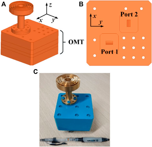
FIGURE 8. Photographs of (A) Co-simulation model of the OMT and horn antenna. (B) Bottom view of the OMT. (C) Fabricated dual polarized horn antenna with OMT.
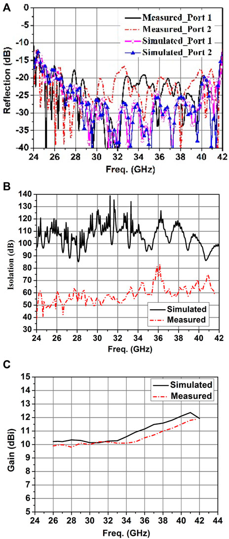
FIGURE 9. Simulated and measured results of the dual-polarized corrugated horn antenna with OMT. (A) Reflection coefficient. (B) Isolation. (C) Gain.
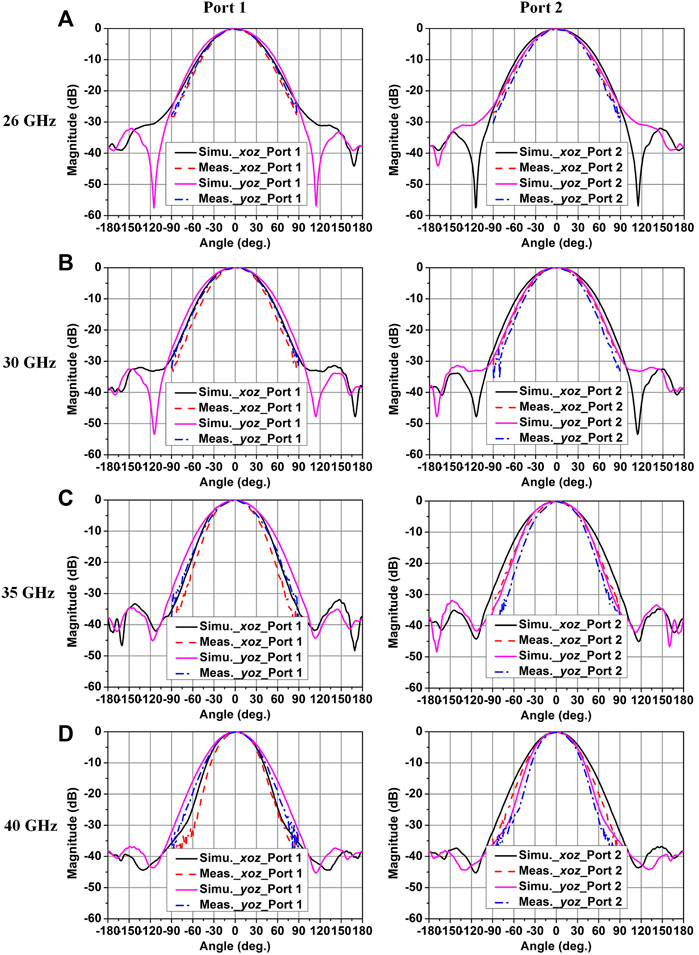
FIGURE 10. Simulated and measured radiation patterns of the dual-polarized horn antenna with OMT at (A) 26 GHz. (B) 30 GHz. (C) 35 GHz. (D) 40 GHz.
A broadband dual-polarized corrugated horn antenna incorporated a turnstile orthomode transducer (OMT) has been presented and verified at Ka-band (26.5–40 GHz). A turnstile OMT is designed to achieve dual polarization with high isolation. A broadband linearly polarized corrugated horn antenna is designed with five-stage choke rings achieving stable and symmetric radiation patterns within the bandwidth. The antenna system including the turnstile OMT and corrugated horn antenna shows a 50.7% −15 dB impedance bandwidth at two input ports, respectively. The proposed dual-polarized antenna system is a promising candidate for future 5G applications.
The original contributions presented in the study are included in the article/Supplementary Material, further inquiries can be directed to the corresponding authors.
JX: Conceptualization, data curation, formal analysis, funding acquisition, investigation, methodology, project administration, resources, software, supervision, validation, visualization, writing—original draft, writing—review and editing. GT: Conceptualization, formal analysis, investigation, methodology, writing—review and editing. HL: Conceptualization, formal analysis, funding acquisition, investigation, software, writing—review and editing. TD: Conceptualization, investigation, writing—review and editing. QY: Conceptualization, formal analysis, funding acquisition, investigation, methodology, project administration, resources, supervision, writing—review and editing.
This work was supported in part by the Natural Science Foundation of Fujian Province under Grant 2020J05149, Project JAT190298 through the Education Department of Fujian Province, and also supported in part by the National Natural Science Foundation of China under Grant 62071152.
GT was employed by the company Beijing Xibao Electronic Technology Co. Ltd.
The remaining authors declare that the research was conducted in the absence of any commercial or financial relationships that could be construed as a potential conflict of interest.
All claims expressed in this article are solely those of the authors and do not necessarily represent those of their affiliated organizations, or those of the publisher, the editors and the reviewers. Any product that may be evaluated in this article, or claim that may be made by its manufacturer, is not guaranteed or endorsed by the publisher.
1. Olk AE, Liu M, Powell DA. Printed Tapered Leaky-Wave Antennas for W-Band Frequencies. IEEE Trans Antennas Propagat (2022) 70(2):900–10. doi:10.1109/tap.2021.3111291
2. Xu K-D, Xia S, Jiang Y, Guo Y-J, Liu Y, Wu R, et al. Compact Millimeter-Wave On-Chip Dual-Band Bandpass Filter in 0.15-μm GaAs Technology. IEEE J Electron Devices Soc (2022) 10:152–6. doi:10.1109/jeds.2022.3143999
3. Al-Tarifi MA, Filipovic DS. On the Design and Fabrication of W-Band Stabilised-Pattern Dual-Polarised Horn Antennas with DMLS and CNC. IET Microw Antennas Propag (2017) 11:1930–5.
4. Zhang L, He W, Donaldson CR, Smith GM, Robertson DA, Hunter RI, et al. Optimization and Measurement of a Smoothly Profiled Horn for a W-Band Gyro-TWA. IEEE Trans Electron Devices (2017) 64(6):2665–9. doi:10.1109/ted.2017.2687949
5. Montofré DA, Molina R, Khudchenko A, Hesper R, Baryshev AM, Reyes N, et al. High-Performance Smooth-Walled Horn Antennas for THz Frequency Range: Design and Evaluation. IEEE Trans Thz Sci Technol (2019) 9(6):587–97. doi:10.1109/tthz.2019.2938985
6. McKay JE, Robertson DA, Speirs PJ, Hunter RI, Wylde RJ, Smith GM. Compact Corrugated Feedhorns with High Gaussian Coupling Efficiency and $-60\;\text{dB}$ Sidelobes. IEEE Trans Antennas Propagat (2016) 64(6):2518–22. doi:10.1109/tap.2016.2543799
7. Sekiguchi S, Sugimoto M, Shu S, Sekimoto Y, Mitsui K, Nishino T, et al. Broadband Corrugated Horn Array with Direct Machined Fabrication. IEEE Trans Thz Sci Technol (2017) 7(1):36–41. doi:10.1109/TTHZ.2016.2634321
8. Gonzalez A, Kaneko K, Kojima T, Asayama S, Uzawa Y. Terahertz Corrugated Horns (1.25-- 1.57 THz): Design, Gaussian Modeling, and Measurements. IEEE Trans Thz Sci Technol (2017) 7(1):42–52. doi:10.1109/tthz.2017.2758789
9. Agnihotri I, Sharma SK. Design of a 3D Metal Printed Axial Corrugated Horn Antenna Covering Full Ka-Band. Antennas Wirel Propag Lett (2020) 19(4):522–6. doi:10.1109/lawp.2020.2967996
10. Qi J-R, Dang Y, Zhang P-Y, Chou H-T, Ju H-S. Dual-Band Circular-Polarization Horn Antenna with Completely Inhomogeneous Corrugations. Antennas Wirel Propag Lett (2020) 19(5):751–5. doi:10.1109/lawp.2020.2978878
11. Feng R, Ratni B, Yi J, Zhang H, de Lustrac A, Burokur SN. Versatile Metasurface Platform for Electromagnetic Wave Tailoring. Photon Res (2021) 9:1650–9. doi:10.1364/prj.428853
12. Lin M, Liu C, Yi J, Jiang ZH, Chen X, Xu HX, et al. Chirality-intrigged Spin-Selective Metasurface and Applications in Generating Orbital Angular Momentum. IEEE Trans Antennas Propag., Early Access (2022). doi:10.1109/tap.2022.3140491
13. Li J, Hu P, Chen J, Xu K-D, Mao C-X, Zhang XY. Dual-polarized Duplex Base-Station Antenna with a Duplexer-Integrated Balun. Antennas Wirel Propag Lett (2022) 21(2):317–21. doi:10.1109/lawp.2021.3130032
14. Jacobs OB, Odendaal JW, Joubert J. Quad-Ridge Horn Antenna with Elliptically Shaped Sidewalls. IEEE Trans Antennas Propagat (2013) 61(6):2948–55. doi:10.1109/tap.2013.2254436
15. Manafi S, Al-Tarifi M, Filipovic DS. 45-110 GHz Quad-Ridge Horn with Stable Gain and Symmetric Beam. IEEE Trans Antennas Propagat (2017) 65(9):4858–63. doi:10.1109/tap.2017.2724069
16. Flygare J, Pantaleev M. Dielectrically Loaded Quad-Ridge Flared Horn for Beamwidth Control over Decade Bandwidth-Optimization, Manufacture, and Measurement. IEEE Trans Antennas Propagat (2020) 68(1):207–16. doi:10.1109/tap.2019.2940529
17. Bøifot A, Lier E, Schaug-Pettersen T. Simple and Broadband Orthomode Transducer. IEE Proc H (Microwaves, Antennas Propagation) (1990) 137:396–400.
18. Asayama Si., Kamikura M. Development of Double-Ridged Wavegide Orthomode Transducer for the 2 MM Band. J Infrared Milli Terahz Waves (2009) 30:573–9. doi:10.1007/s10762-009-9475-9
19. Navarrini A, Nesti R. Symmetric Reverse-Coupling Waveguide Orthomode Transducer for the 3-mm Band. IEEE Trans Microwave Theor Techn. (2009) 57(1):80–8. doi:10.1109/tmtt.2008.2008943
20. Leal-Sevillano CA, Reck TJ, Chattopadhyay G, Ruiz-Cruz JA, Montejo-Garai JR, Rebollar JM. Development of a Wideband Compact Orthomode Transducer for the 180-270 GHz Band. IEEE Trans Thz Sci Technol (2014) 4(5):634–6. doi:10.1109/tthz.2014.2336540
21. Tribak A, Cano JL, Mediavilla A, Boussouis M. Octave Bandwidth Compact Turnstile-Based Orthomode Transducer. IEEE Microw Wireless Compon Lett (2010) 20(10):539–41. doi:10.1109/lmwc.2010.2060261
22. Henke D, Claude S. Minimizing RF Performance Spikes in a Cryogenic Orthomode Transducer (OMT). IEEE Trans Microwave Theor Techn. (2014) 62(4):840–50. doi:10.1109/tmtt.2014.2309551
23. Cano JL, Mediavilla A. Quasi-Octave Bandwidth In-phase Three-Layer Platelet Orthomode Transducer Using Improved Power Combiners. IEEE Microw Wireless Compon Lett (2018) 28(12):1086–8. doi:10.1109/lmwc.2018.2874160
24. Gomez-Torrent A, Shah U, Oberhammer J. Compact Silicon-Micromachined Wideband 220-330-GHz Turnstile Orthomode Transducer. IEEE Trans Thz Sci Technol (2019) 9(1):38–46. doi:10.1109/tthz.2018.2882745
Keywords: dual-polarized antenna, corrugated horn antenna, orthomode transducer (OMT), turnstile junction, Ka-band
Citation: Xiao J, Teni G, Li H, Ding T and Ye Q (2022) A Dual-Polarized Horn Antenna Covering Full Ka-Band Using Turnstile OMT. Front. Phys. 10:880606. doi: 10.3389/fphy.2022.880606
Received: 21 February 2022; Accepted: 10 March 2022;
Published: 05 April 2022.
Edited by:
Kai-Da Xu, Xi’an Jiaotong University, ChinaReviewed by:
Jianjia Yi, Xi’an Jiaotong University, ChinaCopyright © 2022 Xiao, Teni, Li, Ding and Ye. This is an open-access article distributed under the terms of the Creative Commons Attribution License (CC BY). The use, distribution or reproduction in other forums is permitted, provided the original author(s) and the copyright owner(s) are credited and that the original publication in this journal is cited, in accordance with accepted academic practice. No use, distribution or reproduction is permitted which does not comply with these terms.
*Correspondence: Hongmei Li, bGlob25nbWVpQGhpdC5lZHUuY24=; Qiubo Ye, cWJ5ZUBqbXUuZWR1LmNu
Disclaimer: All claims expressed in this article are solely those of the authors and do not necessarily represent those of their affiliated organizations, or those of the publisher, the editors and the reviewers. Any product that may be evaluated in this article or claim that may be made by its manufacturer is not guaranteed or endorsed by the publisher.
Research integrity at Frontiers
Learn more about the work of our research integrity team to safeguard the quality of each article we publish.