- State Key Laboratory of Precision Measurement Technology and Instruments, Department of Precision Instruments, Tsinghua University, Beijing, China
Aberrations in the optical components and misalignments in the optical system cause a background phase in the coherent illumination. To reconstruct the object phase, the background phase illuminating the object must be measured and subtracted. For diffraction imaging and in-line holography, the traditional phase retrieval method reconstructs the phase diffracting from clear edges. However, it falls into stagnation when solving a background phase slowly varying in the spatial domain. In this study, we propose to solve the background phase using a modulation-based phase retrieval method. Alternative structured phase modulation (ASPM) can be the phase constraint to avoid stagnation when solving the background phase without clear edges. With ASPM, the background phase in the experiment can be efficiently retrieved when 16 phase patterns are employed. The ASPM acts as a phase grating to concentrate the intensities and provides robustness to noise. Compared to the conventional random phase modulations, the ASPM method had a smaller error value in the reconstruction iterations, which leads to a better reconstruction quality. After measuring and subtracting the background phase, the object phase was retrieved using a coherent diffraction imaging system. A phase plate can be accurately reconstructed under three different background phases.
Introduction
Aberrations and misalignments are inevitable in the optical setups of various phase imaging techniques, including interferometric methods [1–5] and diffraction-based methods [6–9]. To measure the complex amplitude, an object is illuminated with a coherent wave. The plane wave [10] or quasi-plane [11, 12] wave is widely used for illumination. With ideal plane-wave illumination, the transmitted wavefront represents the complex amplitude of the object. Typically, in the experiments, there are unavoidable aberrations and misalignments [13–15]. The illumination on the object has an undesirable background phase slowly varying in the spatial domain. The transmitted wavefront is the complex amplitude product of the object and illumination. To acquire the object phase, the background phase must be measured and subtracted.
Various methods have been proposed for the background phase compensation in the interferometric methods, such as off-axis holography techniques [16]. The compensation can be executed numerically during the reconstruction. The background phase can be compensated by generating a virtual phase from the hologram [17, 18] or using polynomial fitting [19, 20]. The aberration compensation can also be mimicked by the computation of a numerical parametric lens [21]. Apart from the numerical method, measuring and subtracting the background phase is a straightforward approach [22]. Complete information on system aberration is calculated from three laterally shifted phase images using spiral phase integration [23]. In angular scanning digital holography setup, pupil aberrations are recovered by utilizing the cross-spectral density between optical fields at various incident angles [24]. For off-axis digital holography, the background phase can be measured directly. The phase of an object is acquired after background elimination [25]. In phase-shifting methods, the background phase is measured directly [26] or eliminated by numerical methods [27]. The aberrations can also be compensated using Zernike polynomials [28].
In diffraction imaging methods, iterative phase retrieval methods are used to retrieve the phase [29, 30]. The basic procedure of the algorithm is the alternating propagation of the estimated wavefront between the planes of interest and the recorded intensity. There is conjugated noise while propagating the intensity. Traditional phase retrieval methods used constraints to eliminate the conjugated noise. The Gerchberg-Saxton (GS) algorithm [31] used the amplitude of the wavefront of interest to be a strong constraint. Then, Fienup modified the GS algorithm by using a loose non-negative constraint [32] or support constraint [33]. A support constraint was widely used as a priori information for phase retrieval [34, 35]. The support region was artificially created by coherently illuminating a finite region of an extended object or a large scene [36]. The wavefront inside the support region was reconstructed iteratively. The noise outside the support region was weakened or abandoned [37].
In a diffraction imaging setup, there is no reference beam while recording the diffracted hologram. The background phase compensation is hard to execute using the aforementioned numerical methods. The background phase needs to be measured. The traditional phase retrieval method performs well when solving the phase diffracting from clear edges. Using simulated data, the phase inside the support region can be rapidly reconstructed [37]. When solving the background phase without clear edges, the reconstruction algorithm stagnates [36]. In the experiment, the intensity data was with environmental noise. The background phase is unsolvable based on its intensity pattern with noise using traditional phase-retrieval methods. Diversities in the diffraction intensities need to be detected adequately for retrieving a smooth background phase [38, 39].
Modulations can also be used as modulation constraints to achieve successful phase retrieval. With multiple phase modulations, the wavefront can be fully reconstructed without finite support constraints [40]. Using shifting illumination, a large area of the specimen can be reconstructed at high resolution [41–43]. A novel topological modulation provides an effective dynamic range in the recorded intensities [44]. The two-dimensional circular grating array is designed for the simultaneous acquisition of scattering images in all possible directions using a single shot [45]. With a phase-stepping process, phase retrieval can be made with a high signal-to-noise ratio (SNR) with a low dose x-ray illumination [46]. Progress in holographic imaging is made with random phase modulation using metasurface. A reference-free holographic image sensor can be made with a random diffuser [47]. High-precision quantitative phase gradient imaging can be made with a single shot using two coded metasurface layers [48]. With phase modulations, phase retrieval methods can be applied to building a novel wavefront sensor. Traditional wavefront sensor such as the Shack-Hartmann wavefront sensor has a lateral resolution limited by the size of micro-lens [49]. The wavefront sensing is made with a 10-megapixel lateral resolution using random phase modulations (RPM) on a spatial light modulator (SLM) [50]. To reduce the modulation defects on an SLM [51], the alternative structured phase modulations (ASPM) were designed for providing a reliable phase modulation on the SLM and increasing the robustness of data acquisition [52]. The structured phase modulation can also be used to shift the high spatial frequency terms into the diffraction-limited imaging setup, which is an effective approach to enhance the resolution of holographic microscopy [53, 54] or phase-shifting interferometry [55, 56].
In this study, we propose to solve the background phase using a modulation-based phase retrieval method. The ASPM can be the phase constraint to avoid stagnation when solving the background phase slowly varying in the spatial domain. The structured phase modulation patterns consisted of periodic phase bars. Two adjacent patterns were orthogonally placed to form one pair of ASPM patterns. The measured wavefront was perturbed by the ASPM patterns, and the modulated intensities were recorded correspondingly. Then, a modified GS algorithm was performed for reconstruction. The modulated intensities are concentrated by the phase gratings, which makes the method robust to noise. The algorithm rapidly converged in 100 iterations when solving the background phase in an experimental setup. After background phase subtraction, the object phase can be reconstructed accurately. A phase plate was experimentally studied and reconstructed using illumination with three background phases. The RPM patterns in ref. 39 [50] were also evaluated by measuring a phase object in the same experimental setup. The root means square error (RMSE) curves showed that the ASPM method had a smaller error value in the reconstruction iterations, which leads to a better reconstruction quality. The ASPM method is reliable for background subtraction and measuring an object’s phase.
Retrieve the Object Phase in a Diffraction Imaging System
A schematic of the diffraction imaging setup used to measure the phase object is shown in Figure 1A. The investigated object had a complex amplitude, where
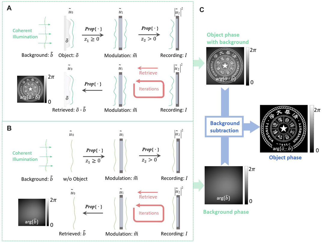
FIGURE 1. Schematic of the diffraction imaging technique when recording and retrieving. (A) Measuring and reconstructing the object phase with the background phase. (B) Measuring and reconstructing the background phase.
The illumination has a phase distribution, especially when there are some misalignments and aberrations in the setup. As shown in Figure 1A, the illumination on the object plane is
where Prop{·} represents the propagation calculator,
A schematic of the retrieval of the object phase is shown in Figure 1A. In the reconstruction process, the phase-retrieval algorithm proceeded between the modulation plane and the recording plane. Using the support or modulation constraint and the recorded intensity constraint
The background phase must be measured and subtracted from
Retrieving a Background Phase Using the Alternative Structured Phase Modulation Method
Reconstruct a Complex Wavefront Using the Alternative Structured Phase Modulation Method
A schematic of the ASPM method is shown in Figure 2A. A phase object was illuminated as
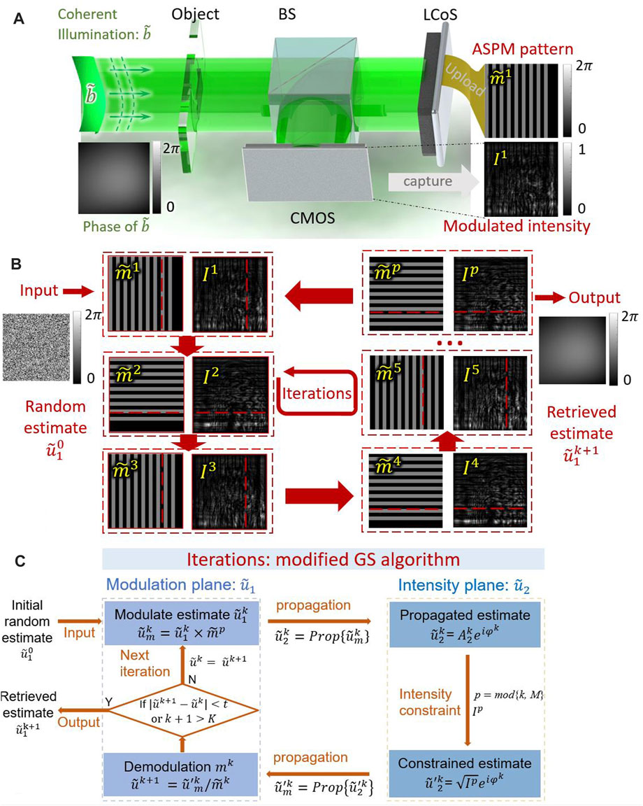
FIGURE 2. (A) Schematic of diffraction imaging using the ASPM method. (B) Uploaded ASPM patterns on the LCoS and corresponding modulated intensities. (C) Flowchart of the iterations using ASPM method.
As shown in Figure 2(and, an ASPM pattern is composed of bars and forms a structured phase modulation
where
The intensity
A modified GS algorithm was used for the ASPM method. A flowchart of the algorithm is presented in Figure 2C. The algorithm alternately propagates the estimated wavefront between the modulation and intensity planes. Conjugate noise was eliminated by the constraints on the two planes. An initial random estimate of the measured wavefront
After one iteration, the conjugated terms were suppressed with constraints. After k iterations, the refreshed estimated wavefront
In the ASPM method, the multiple phase modulations are made by shifting and rotating the phase grating perpendicular to the optical axis. There is significant variance in the captured intensities from the modulations. The diversities in the multiple intensities provide sufficient constraints for good convergence of iterations. More constraints result in a solution closer to the ground truth.
Simulation of Retrieving a Background Phase Using the Alternative Structured Phase Modulation Method
A simulation was performed for retrieving a background phase using the ASPM method. A 200×200-pixel concave wavefront was measured as the ground truth, as shown in Figure 3A. The phase component had a maximum value of 0.5
where
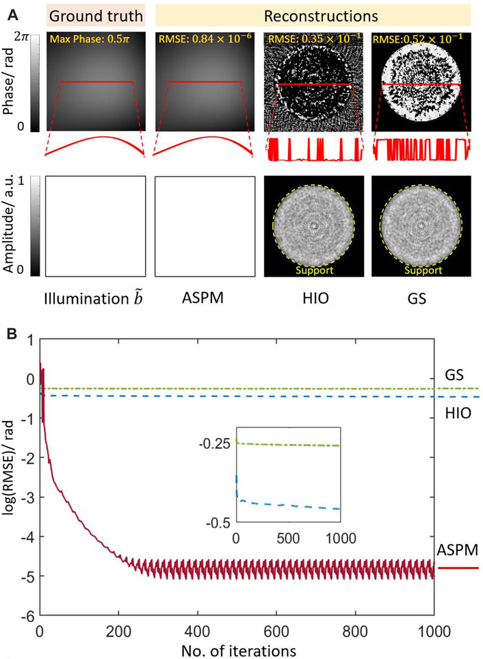
FIGURE 3. (A) Ground truth of the wavefront and reconstructed phase and amplitude components using the ASPM, HIO, and GS methods. (B) The logarithm of the RMSE of the ASPM, GS, and HIO methods with 1000 iterations. log(RMSE): logarithm of the RMSE of the calculated phase and the ground truth.
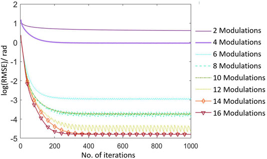
The concave smooth wavefront in Figure 3A was modulated with eight groups of ASPM patterns. The period of each group of the ASPM patterns was from 2 to 16 pixels, with a duty ratio of 50%. After the modulation in both the x- and y- directions, the pattern was shifted with one pixel. A modified GS algorithm was then used to work with the constraints for reconstruction. The logarithm of the RMSE between the ground truth and the calculated phase during the iterations is shown in Figure 4. A total of 1000 iterations were performed during the reconstruction process. When there are 2 or 4 modulations, the reconstruction cannot be made. There are three unknowns in the phase retrieval problem, which are the phase of the diffracted wavefront, phase and amplitude of the measured wavefront. At least three pairs of modulations in x- and y- directions are needed for reconstruction. As the number of modulations increases from 6, the concave smooth phase can be reconstructed successfully. Structured phase patterns are modulation constraints. The corresponding recorded modulated intensities were the intensity constraints. Multiple modulations provide sufficient constraints for noise elimination. The convergence of the iterations and the accuracy of the reconstruction are increased with the number of modulations. In the following simulations and experiments, 16 modulations are used for a good result.
With 16 modulations, The ASPM pattern was shifted eight times in both the x- and y-directions. As shown in Figure 3B, during the first 100 iterations, the algorithm converges rapidly, which shows the efficiency of the ASPM method for error elimination. After 300 iterations, the algorithm converges to the final result. Compared to the ground truth, the RM phase component reached approximately 0.84
The classical GS and hybrid-input-output (HIO) [13] algorithms were also used to measure the concave wavefront. The measured wavefront was the same as that in the ASPM method. To apply the GS and HIO method, the wavefront was constrained with a support region, which was a round central pass filter with a radius of 80 pixels. In the GS algorithm, the wavefront inside the support region was completely passed, and outside the region was blocked. In the HIO algorithm, the wavefront inside the support region was completely passed and outside the region was suppressed by a factor of 0.07 in every iteration. Both the GS and HIO algorithms failed to solve the background phase
In the classical GS and HIO method, the recording and retrieving can be described by Eqs. 7, 8. There is a support region C on the measured complex wavefront
In the ASPM method, the recording and retrieving can be described by Eqs. 9, 10. The measured complex wavefront
Experiments on Reconstructing an Object Phase Using the Alternative Structured Phase Modulation
Calibrating the Phase Modulation of a Spatial Light Modulator
In the ASPM method, the designed phase patterns are the modulation constraints in the reconstruction iterations. The modulated phase is a priori information for eliminating conjugated terms. Quantitative phase modulation is required for successful reconstruction. In addition, the ASPM method requires multiple modulations and measurements to guarantee the convergence of the algorithm and robustness to noise. Phase calibration of the LCoS modulation benefits the acquisition of good experimental results.
In this study, phase modulations were made using an LCoS (Holoeye GAEA-2-vis). LCoS is a pixelated digital device that can quantitatively modulate the phase. Owing to the limited manufacturing process and nonlinear optical response of the liquid crystal [59], the LCoS must be calibrated before being used. Many calibration methods have been proposed [60–62]. In this study, the LCoS was calibrated using an efficient and convenient self-referenced calibration method [63, 64]. Using a blazed-grating pattern [65], the phase modulation was measured with an accuracy of 0.06
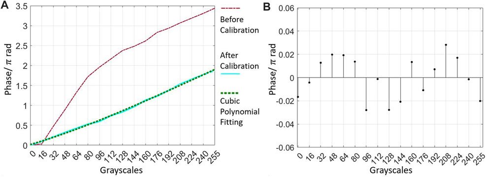
FIGURE 5. (A) Modulation curves of the LCoS before and after calibration and curve using the cubic polynomial fitting method. (B) Residuals of the fitted curve.
Measuring the object phase with background subtraction.
A phase plate was experimentally studied using the ASPM method. The setup was illuminated at 532 nm wavelength. The polarization of the laser was adjusted by a λ⁄2 wave plate. The illumination was experimentally adjusted to be collimated but it was still not a perfect plane wave. The interferogram of the illumination was measured using a shear interferometer (Thorlabs, SI254), as shown in Figure 6A. The fringe pattern shows that the illumination
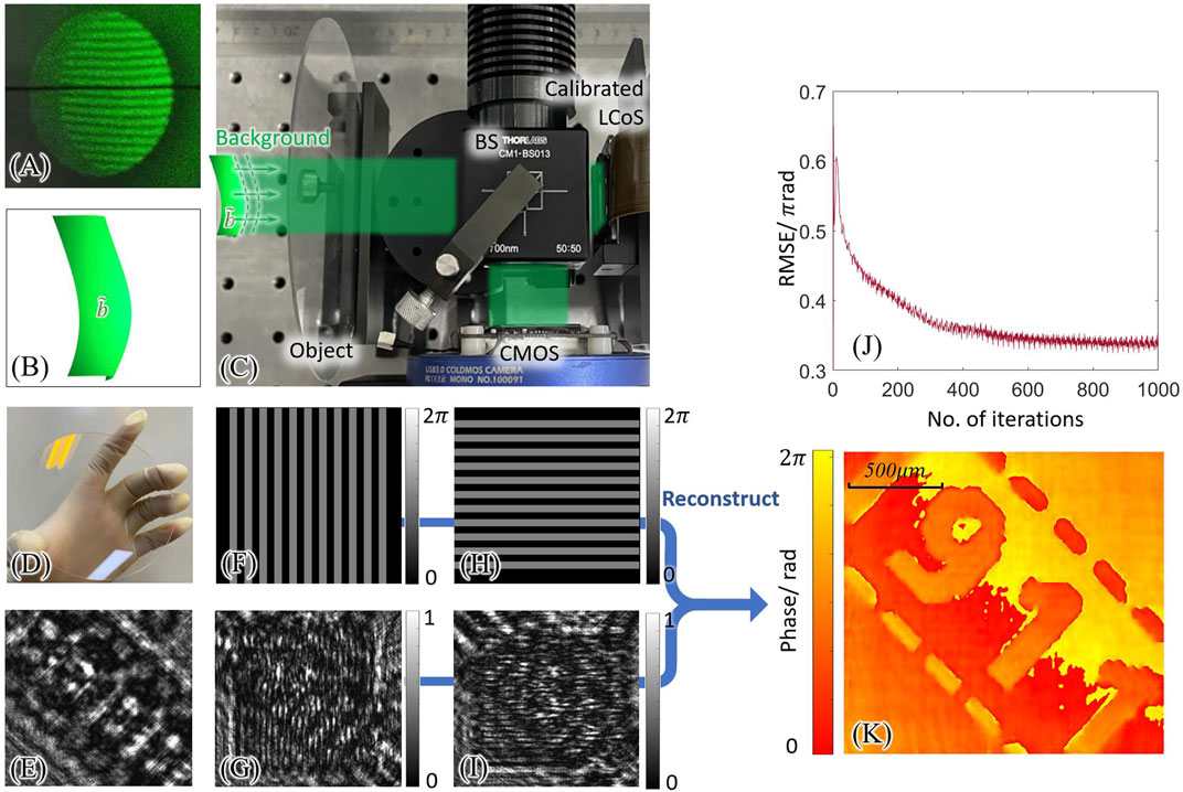
FIGURE 6. Measuring a phase object using illumination with background phase. (A) The fringe pattern on a shearing interferometer (Thorlabs SI254) for measuring the background wavefront. (B) Schematic of the illumination with a background phase. (C) Schematic of a coherent diffraction imaging setup. (D) Picture of the object, a phase plate. (E) Diffraction pattern of the measured object. (F,H): Two of the ASPM patterns in x- and y- direction. (G,F): Captured intensities of the modulated wavefront. (J) The curve of the RMSE between the calculated wavefronts of adjacent iterations. (K) The reconstructed phase of the object with distortion in the illumination.
The complex wavefront
Using the ASPM method, illumination
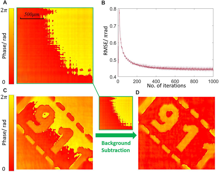
FIGURE 7. (A) Reconstructed phase of the illumination in the experiment using the ASPM method. (B) RMSE during reconstruction. (C) The reconstructed phase of the object with an illumination background. (D) Object phase with background subtraction.
In the experiment, the illumination was expanded, and a schematic of the phase profile of the illumination is shown in Figure 8A. The phase plate was measured experimentally using three sections of illumination. After modulations and captures using the central section of the illumination, the next sections at an interval of 250 pixels were used to illuminate the object. Using the ASPM method, the wavefronts of the three illumination sections were reconstructed. The background phases of the illumination sections are shown in Figure 8B. After subtracting the phase under illumination, the phase of the object was measured under the three illumination sections. The phase profiles before and after subtraction are shown in Figures 8C, D. The phase values along the dotted line in Figures 8C, D are plotted in Figures 9A, B. Before the subtraction, the phase was visually distinguished, but difficult to evaluate quantitatively. The strong background phases destroyed the investigated phase from the object. The phase profile of the reconstructed wavefront could not represent the object phase. After subtraction, the phase values along the line were quantitatively evaluated. The measured phase values under different illuminations matched well.
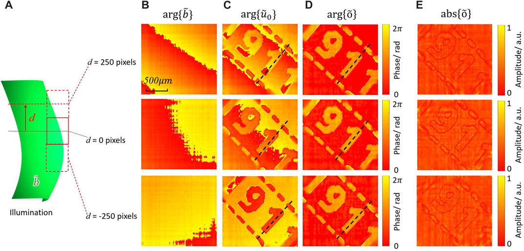
FIGURE 8. Measuring the phase object using three sections of the illumination. (A) Schematic of the illumination in the experiment. (B) The reconstructed phase of different sections of the illumination. (C) Reconstructed object phase without background subtraction. (D) Reconstructed object phase with background subtraction. (E) Reconstructed object amplitude with background subtraction.
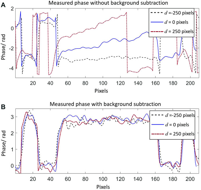
FIGURE 9. (A) Measured phase along the line of the object without background subtraction. (B) Measured phase along the line with background subtraction.
Evaluation of the Alternative Structured Phase Modulation and RPM Methods
The ASPM and RPM methods were experimentally evaluated. Sixteen ASPM patterns with a period of 40 pixels were used for modulation. For comparison, sixteen RPM patterns with a pitch size of 40 pixels were used for modulation. One of the RPM and ASPM patterns is shown in Figures 10A, B. Using the setup in Figures 6A, C phase object illuminated with a background phase was studied using the ASPM and RPM methods, respectively. Using the two methods, the phase of the background and object can be iteratively reconstructed, as shown in Figures 10C–H. The RMSEs curves of the two methods during iterations are shown in Figures 10I, J, which shows that the ASPM method has a smaller error during the reconstruction for a background phase and object phase. Compared to the RPM method, the ASPM method has a better reconstruction quality for the background phase and object phase.
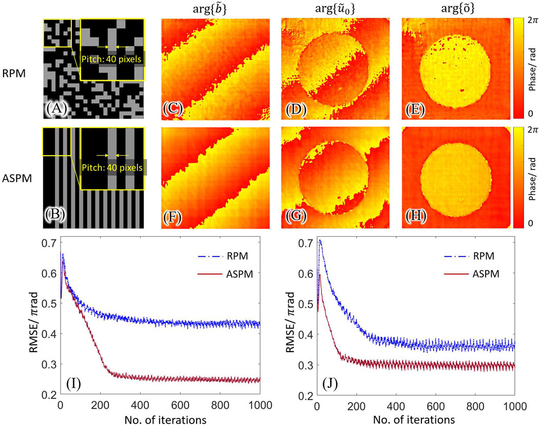
FIGURE 10. Evaluation of the ASPM and RPM methods. (A) One of the sixteen RPM patterns. (B) One of the sixteen ASPM patterns. (C–E) Reconstructed background phase, object phase without background subtraction, and object phase with background subtraction using RPM method. (F–H) Reconstructed background phase, object phase without background subtraction, and object phase with background subtraction using the ASPM method. (I) RMSE in the background reconstruction using the ASPM and RPM methods. (J) RMSE in the object phase reconstruction using the ASPM and RPM methods.
In the proposed method, the spatial light modulator is used for phase modulation. SLM is a digitalized device and has a limited modulation bandwidth. The phases in the RPM are randomly distributed in a high spatial complexity, which makes the RPM hard to be accurately modulated using an available SLM. The phases in the ASPM are the same in one direction and vary periodically in the other direction. Compared to the RPM, the ASPM have lower complexity and is friendly for SLM modulation. Besides, there us environmental noise during the experiment. The ASPM patterns act as the phase gratings and concentrate the modulated intensities, which provides robustness to noise.
Conclusion
In this study, the ASPM method was used to retrieve the background phase in the illumination. Three statics background phases were reconstructed in a diffraction imaging setup, which is difficult to use in traditional phase-retrieval methods. A phase plate was investigated under three background illuminations, and the object phase was reconstructed. The ASPM method can retrieve the complex wavefront gathered from a lens set. With the ASPM method, various wavefront sensing techniques can be used for quantitative phase imaging. The method is also capable of measuring an object with a phase slowly varying in the spatial domain. The background phases in various types of imaging setups, such as in-line holography, can be retrieved and compensated using the ASPM method. In this work, the modulations were made with an SLM working at a 60 Hz refreshing rate. Sixteen acquisitions for measuring a background phase can be made in 0.27 s. The acquisition time can be reduced by using a faster modulation device, such as ferroelectric SLM.
Data Availability Statement
The raw data supporting the conclusions of this article will be made available by the authors, without undue reservation.
Author Contributions
LC and FY conceived and supervised the project. RL performed experiments and data analysis. FY, RL, and LC contributed to data analysis. RL and LC wrote the draft of the manuscript; All the authors edited the manuscript.
Funding
National Nature Science Foundation of China (61775117).
Conflict of Interest
The authors declare that the research was conducted in the absence of any commercial or financial relationships that could be construed as a potential conflict of interest.
Publisher’s Note
All claims expressed in this article are solely those of the authors and do not necessarily represent those of their affiliated organizations, or those of the publisher, the editors and the reviewers. Any product that may be evaluated in this article, or claim that may be made by its manufacturer, is not guaranteed or endorsed by the publisher.
References
1. Zhou W, Yu Y, Asundi A. Study on Aberration Suppressing Methods in Digital Micro-holography. Opt Lasers Eng (2009) 47(2):264–70. doi:10.1016/j.optlaseng.2008.04.026
2. Javidi B, Carnicer A, Anand A, Barbastathis G, Chen W, Ferraro P, et al. Roadmap on Digital Holography [Invited]. Opt. Express (2021) 29(22):35078–118. doi:10.1364/OE.435915
3. Yan F, Yan H, Yu Y, Zhou W, Asundi A. The Suppression of Phase Error by Applying Window Functions to Digital Holography. Opt Lasers Eng (2016) 86:206–15. doi:10.1016/j.optlaseng.2016.05.022
4. Sheridan JT, Kostuk RK, Gil AF, Wang Y, Lu W, Zhong H, et al. Roadmap on Holography. J Opt (2020) 22(12):123002. doi:10.1088/2040-8986/abb3a4
5. Paturzo M, Pagliarulo V, Bianco V, Memmolo P, Miccio L, Merola F, et al. Digital Holography, a Metrological Tool for Quantitative Analysis: Trends and Future Applications. Opt Lasers Eng (2018) 104:32–47. doi:10.1016/j.optlaseng.2017.11.013
6. Miao J, Charalambous P, Kirz J, Sayre D. Extending the Methodology of X-Ray Crystallography to Allow Imaging of Micrometre-Sized Non-crystalline Specimens. Nature (1999) 400(6742):342–4. doi:10.1038/22498
7. Zuo C, Li J, Sun J, Fan Y, Zhang J, Lu L, et al. Transport of Intensity Equation: A Tutorial. Opt Lasers Eng (2020) 135:106187. doi:10.1016/j.optlaseng.2020.106187
8. Latychevskaia T, Longchamp J-N, Fink H-W. When Holography Meets Coherent Diffraction Imaging. Opt. Express (2012) 20(27):28871–92. doi:10.1364/OE.20.028871
9. Wang K, Di J, Li Y, Ren Z, Kemao Q, Zhao J. Transport of Intensity Equation from a Single Intensity Image via Deep Learning. Opt Lasers Eng (2020) 134:106233. doi:10.1016/j.optlaseng.2020.106233
10. Gao Y, Cao L. High-Fidelity Pixel-Super-Resolved Complex Field Reconstruction via Adaptive Smoothing. Opt. Lett. (2020) 45(24):6807–10. doi:10.1364/OL.409697
11. Ozcan A, McLeod E. Lensless Imaging and Sensing. Annu. Rev. Biomed. Eng. (2016) 18(1):77–102. doi:10.1146/annurev-bioeng-092515-010849
12. Rivenson Y, Zhang Y, Günaydın H, Teng D, Ozcan A. Phase Recovery and Holographic Image Reconstruction Using Deep Learning in Neural Networks. Light Sci Appl (2018) 7(2):17141. doi:10.1038/lsa.2017.141
13. Migukin A, Agour M, Katkovnik V. Phase Retrieval in 4f Optical System: Background Compensation and Sparse Regularization of Object with Binary Amplitude. Appl. Opt. (2013) 52(1):A269–A80. doi:10.1364/AO.52.00A269
14. Min J, Yao B, Gao P, Ma B, Yan S, Peng F, et al. Wave-Front Curvature Compensation of Polarization Phase-Shifting Digital Holography. optik (2012) 123:1525–9. doi:10.1016/j.ijleo.2011.09.018
15. He X, Tao H, Pan X, Liu C, Zhu J. High-Quality Laser Beam Diagnostics Using Modified Coherent Phase Modulation Imaging. Opt. Express (2018) 26(5):6239–48. doi:10.1364/OE.26.006239
16. Cuche E, Marquet P, Depeursinge C. Spatial Filtering for Zero-Order and Twin-Image Elimination in Digital off-Axis Holography. Appl. Opt. (2000) 39(23):4070–5. doi:10.1364/AO.39.004070
17. Seo KW, Choi YS, Seo ES, Lee SJ. Aberration Compensation for Objective Phase Curvature in Phase Holographic Microscopy. Opt. Lett. (2012) 37(23):4976–8. doi:10.1364/OL.37.004976
18. Di J, Zhao J, Sun W, Jiang H, Yan X. Phase Aberration Compensation of Digital Holographic Microscopy Based on Least Squares Surface Fitting. Opt Commun (2009) 282(19):3873–7. doi:10.1016/j.optcom.2009.06.049
19. Yu H, Jia S, Dong J, Huang D, Xu S. Phase Curvature Compensation in Digital Holographic Microscopy Based on Phase Gradient Fitting and Optimization. J. Opt. Soc. Am. A (2019) 36(12):D1–D6. doi:10.1364/JOSAA.36.0000D1
20. Miccio L, Alfieri D, Grilli S, Ferraro P, Finizio A, De Petrocellis L, et al. Direct Full Compensation of the Aberrations in Quantitative Phase Microscopy of Thin Objects by a Single Digital Hologram. Appl. Phys. Lett. (2007) 90(4):041104. doi:10.1063/1.2432287
21. Colomb T, Montfort F, Kühn J, Aspert N, Cuche E, Marian A, et al. Numerical Parametric Lens for Shifting, Magnification, and Complete Aberration Compensation in Digital Holographic Microscopy. J. Opt. Soc. Am. A (2006) 23(12):3177–90. doi:10.1364/JOSAA.23.003177
22. Jianglei D., Jianlin Z., Qi F., Hongzhen J., Weiwei S. Phase Correction of Wavefront Reconstruction in Digital Holographic Microscopy. Acta Optica Sinica (2008) 28(1):56–61. doi:10.3788/aos20082801.0056
23. Choi I, Lee K, Park Y. Compensation of Aberration in Quantitative Phase Imaging Using Lateral Shifting and Spiral Phase Integration. Opt. Express (2017) 25(24):30771–9. doi:10.1364/OE.25.030771
24. Baek Y, Hugonnet H, Park Y. Pupil-Aberration Calibration with Controlled Illumination for Quantitative Phase Imaging. Opt. Express (2021) 29(14):22127–35. doi:10.1364/OE.426080
25. Stadelmaier A, Massig JH. Compensation of Lens Aberrations in Digital Holography. Opt. Lett. (2000) 25(22):1630–2. doi:10.1364/OL.25.001630
26. Liu Q, Wang Y, He J, Ji F. Phase Shift Extraction and Wavefront Retrieval from Interferograms with Background and Contrast Fluctuations. J. Opt. (2015) 17(2):025704. doi:10.1088/2040-8978/17/2/025704
27. Yatabe K, Ishikawa K, Oikawa Y. Simple, Flexible, and Accurate Phase Retrieval Method for Generalized Phase-Shifting Interferometry. J. Opt. Soc. Am. A (2017) 34(1):87–96. doi:10.1364/JOSAA.34.000087
28.RF Oliver, S Johannes, B Albrecht, and S Horst, editors. Measurement of the Wave Aberrations of Holographic Optical Lens Elements. Prague, Czech Republic: ProcSPIE (1993).
29. Brady DJ, Choi K, Marks DL, Horisaki R, Lim S. Compressive Holography. Opt. Express (2009) 17(15):13040–9. doi:10.1364/OE.17.013040
30. Huang Z, Memmolo P, Ferraro P, Cao L. Dual-Plane Coupled Phase Retrieval for Non-prior Holographic Imaging. PhotoniX (2022) 3(1):3. doi:10.1186/s43074-021-00046-w
31. Gerchberg RWA. Practical Algorithm for the Determination of Phase from Image and Diffraction Plane Pictures. Optik (1971) 35(2):237
32. Fienup JR. Reconstruction of an Object from the Modulus of its Fourier Transform. Opt. Lett. (1978) 3(1):27–9. doi:10.1364/OL.3.000027
33. Fienup JR. Reconstruction of a Complex-Valued Object from the Modulus of its Fourier Transform Using a Support Constraint. J. Opt. Soc. Am. A (1987) 4(1):118–23. doi:10.1364/JOSAA.4.000118
34. Zhang F, Chen B, Morrison GR, Vila-Comamala J, Guizar-Sicairos M, Robinson IK. Phase Retrieval by Coherent Modulation Imaging. Nat Commun (2016) 7(1):13367. doi:10.1038/ncomms13367
35. Wang B, Wang Q, Lyu W, Zhang F. Modulator Refinement Algorithm for Coherent Modulation Imaging. Ultramicroscopy (2020) 216:113034. doi:10.1016/j.ultramic.2020.113034
36. Paxman RG, Fienup JR, Clinthorne JT. The Effects of Tapered Illumination and Fourier Intensity Errors on Phase Retrieval. Proc SPIE (1988) 0828. doi:10.1117/12.942098
37. Fienup JR. Phase Retrieval Algorithms: A Comparison. Appl. Opt. (1982) 21(15):2758–69. doi:10.1364/AO.21.002758
38. Almoro PF, Pham QD, Serrano-Garcia DI, Hasegawa S, Hayasaki Y, Takeda M, et al. Enhanced Intensity Variation for Multiple-Plane Phase Retrieval Using a Spatial Light Modulator as a Convenient Tunable Diffuser. Opt. Lett. (2016) 41(10):2161–4. doi:10.1364/OL.41.002161
39. Almoro PF, Waller L, Agour M, Falldorf C, Pedrini G, Osten W, et al. Enhanced Deterministic Phase Retrieval Using a Partially Developed Speckle Field. Opt. Lett. (2012) 37(11):2088–90. doi:10.1364/OL.37.002088
40. Zhang F, Pedrini G, Osten W. Phase Retrieval of Arbitrary Complex-Valued Fields through Aperture-Plane Modulation. Phys. Rev. A (2007) 75(4):043805. doi:10.1103/PhysRevA.75.043805
41. Rodenburg JM, Faulkner HML. A Phase Retrieval Algorithm for Shifting Illumination. Appl. Phys. Lett. (2004) 85(20):4795–7. doi:10.1063/1.1823034
42. Zheng G, Horstmeyer R, Yang C. Wide-Field, High-Resolution Fourier Ptychographic Microscopy. Nat Phot (2013) 7(9):739–45. doi:10.1038/nphoton.2013.187
43. Konda PC, Loetgering L, Zhou KC, Xu S, Harvey AR, Horstmeyer R. Fourier Ptychography: Current Applications and Future Promises. Opt. Express (2020) 28(7):9603–30. doi:10.1364/OE.386168
44. Li R, Cao L. Complex Wavefront Sensing Based on Coherent Diffraction Imaging Using Vortex Modulation. Sci Rep (2021) 11(1):9019. doi:10.1038/s41598-021-88523-x
45. Kagias M, Wang Z, Villanueva-Perez P, Jefimovs K, Stampanoni M. 2d-Omnidirectional Hard-X-Ray Scattering Sensitivity in a Single Shot. Phys. Rev. Lett. (2016) 116(9):093902. doi:10.1103/PhysRevLett.116.093902
46. Wang Z, Huang Z, Chen Z, Zhang L, Jiang X, Kang K, et al. Low-Dose Multiple-Information Retrieval Algorithm for X-Ray Grating-Based Imaging. Nucl Instrum Methods Phys Res Sect A Accel Spectrom Detect Assoc Equip (2011) 635(1):103–7. doi:10.1016/j.nima.2011.01.079
47. Lee K, Park Y. Exploiting the Speckle-Correlation Scattering Matrix for a Compact Reference-free Holographic Image Sensor. Nat Commun (2016) 7(1):13359. doi:10.1038/ncomms13359
48. Kwon H, Arbabi E, Kamali SM, Faraji-Dana M, Faraon A. Single-Shot Quantitative Phase Gradient Microscopy Using a System of Multifunctional Metasurfaces. Nat. Photonics (2020) 14(2):109–14. doi:10.1038/s41566-019-0536-x
49. Platt BC, Shack R. History and Principles of Shack-Hartmann Wavefront Sensing. J Refract Surg (2001) 17(5):S573–7. Epub 2001/10/05. doi:10.3928/1081-597X-20010901-13
50. Wu Y, Sharma MK, Veeraraghavan A. WISH: Wavefront Imaging Sensor with High Resolution. Light Sci Appl (2019) 8(1):44. doi:10.1038/s41377-019-0154-x
51. Zhang Z, You Z, Chu D. Fundamentals of Phase-Only Liquid Crystal on Silicon (Lcos) Devices. Light Sci Appl (2014) 3:e213. doi:10.1038/lsa.2014.94
52. Li R, Cao L. Complex Wavefront Sensing Based on Alternative Structured Phase Modulation. Appl. Opt. (2021) 60(4):A48–A53. doi:10.1364/AO.405630
53. Gao P, Pedrini G, Osten W. Structured Illumination for Resolution Enhancement and Autofocusing in Digital Holographic Microscopy. Opt. Lett. (2013) 38(8):1328–30. doi:10.1364/OL.38.001328
54. Zheng J, Gao P, Yao B, Ye T, Lei M, Min J, et al. Digital Holographic Microscopy with Phase-shift-free Structured Illumination. Phot. Res. (2014) 2(3):87–91. doi:10.1364/PRJ.2.000087
55. Gao P, Pedrini G, Osten W. Phase Retrieval with Resolution Enhancement by Using Structured Illumination. Opt. Lett. (2013) 38(24):5204–7. doi:10.1364/OL.38.005204
56. Ma Y, Wen K, Liu M, Zheng J, Chu K, Smith ZJ, et al. Recent Advances in Structured Illumination Microscopy. J. Phys. Photonics (2021) 3(2):024009. doi:10.1088/2515-7647/abdb04
57. Zhang J, Sun J, Chen Q, Zuo C. Resolution Analysis in a Lens-free On-Chip Digital Holographic Microscope. IEEE Trans. Comput. Imaging (2020) 6:697–710. doi:10.1109/TCI.2020.2964247
58. Fan Y, Li J, Lu L, Sun J, Hu Y, Zhang J, et al. Smart Computational Light Microscopes (Sclms) of Smart Computational Imaging Laboratory (Scilab). PhotoniX (2021) 2(1):19. doi:10.1186/s43074-021-00040-2
59. Cirtoaje C, Petrescu E. The Influence of Single-Walled Carbon Nanotubes on the Dynamic Properties of Nematic Liquid Crystals in Magnetic Field. Materials (2019) 12(24):4031. doi:10.3390/ma12244031
60. DeMars LA, Mikuła-Zdańkowska M, Falaggis K, Porras-Aguilar R. Single-Shot Phase Calibration of a Spatial Light Modulator Using Geometric Phase Interferometry. Appl. Opt. (2020) 59(13):D125–D30. doi:10.1364/AO.383610
61. Arias A, Paniagua-Diaz AM, Prieto PM, Roca J, Artal P. Phase-Only Modulation with Two Vertical Aligned Liquid Crystal Devices. Opt. Express (2020) 28(23):34180–9. doi:10.1364/OE.410429
62. Shen Y, Hu Z, Wu D, Ma C, Liu Y. An Open-Source, Accurate, and Iterative Calibration Method for Liquid-Crystal-Based Spatial Light Modulators. Opt Commun (2021) 495:127108. doi:10.1016/j.optcom.2021.127108
63. Li R, Gao Y, Cao L. In Situ Calibration for a Phase-Only Spatial Light Modulator Based on Digital Holography. Opt. Eng. (2020) 59(5):1–10. doi:10.1117/1.OE.59.5.053101
64. Gao Y, Li R, Cao L. Self-Referenced Multiple-Beam Interferometric Method for Robust Phase Calibration of Spatial Light Modulator. Opt. Express (2019) 27(23):34463–71. doi:10.1364/OE.27.034463
65. Márquez A, Martínez-Guardiola F, Francés J, Neipp C, Ramírez M, Calzado E, et al. Analytical Modeling of Blazed Gratings on Two-Dimensional Pixelated Liquid Crystal on Silicon Devices. Opt Eng (2020) 59(4):041208. doi:10.1117/1.OE.59.4.041208
66. Falldorf C, von Kopylow C, Bergmann RB. Wave Field Sensing by Means of Computational Shear Interferometry. J. Opt. Soc. Am. A (2013) 30(10):1905–12. doi:10.1364/JOSAA.30.001905
Keywords: phase retrieval, holography, background subtraction, phase modulation, spatial light modulator
Citation: Li R, Yang F and Cao L (2022) Holographic Imaging Using an Imperfect Plane Wave Illumination With a Background Phase. Front. Phys. 10:880062. doi: 10.3389/fphy.2022.880062
Received: 20 February 2022; Accepted: 20 April 2022;
Published: 19 May 2022.
Edited by:
Yiqi Zhang, Xi’an Jiaotong University, ChinaReviewed by:
YongKeun Park, Korea Advanced Institute of Science and Technology, South KoreaMostafa Agour, Aswan University, Egypt
Copyright © 2022 Li, Yang and Cao. This is an open-access article distributed under the terms of the Creative Commons Attribution License (CC BY). The use, distribution or reproduction in other forums is permitted, provided the original author(s) and the copyright owner(s) are credited and that the original publication in this journal is cited, in accordance with accepted academic practice. No use, distribution or reproduction is permitted which does not comply with these terms.
*Correspondence: Liangcai Cao, Y2xjQHRzaW5naHVhLmVkdS5jbg==
 Rujia Li
 Feng Yang
 Liangcai Cao