- 1School of Physics and Optoelectronic Engineering, Ludong University, Yantai, China
- 2Yantai Magie-Nano Technology Co. Ltd., Yantai, China
The perfect optical vortex has successfully aroused substantial interest from researchers for its central dark hollow caused by spatial phase singularity in recent years. However, the traditional methods of combining the axicon and helical phase to generate the perfect optical vortex lead to an additional focus deviation in the tightly focused systems. Here, we report a multi-foci integration (MFI) method to produce the perfect optical vortex by accumulating a finite number of foci in the focal plane to overcome the additional focus deviation. Furthermore, based on MFI, we superposed two perfect optical vortices to obtain the spot array with controllable phase distribution and the number of spots. This work deepens our knowledge about superposed vortices and facilitates new potential applications. The micromanipulated experimental results agree well with our theoretical simulation. The spot array field provides new opportunities in direct laser writing, optical tweezers, optical communications, and optical storage.
Introduction
Research on vortex beams has attracted increasing attention since L. Allen et al. proved that optical vortex carried orbital angular momentum [1]. Owing to its special optical character and dynamic property by phase gradient [2], vortex beams expanded their applications in various areas, including optical communication [3, 4], micromanipulation [5–8], direct laser writing [9–13], multiple spot arrays [14–19], and complicated optical vortex fields [20–22]. The concept of the perfect optical vortex (POV) has been proposed among vortex beams, whose dark hollow radius does not depend on the topological charge [2, 23, 24]. In 2015, Vaity et al. demonstrated that a POV is the Fourier transform of a Bessel beam [25]. Since then, research has been performed on POV generation [26], modulation [19, 27, 28], and measurements [29, 30]. Particularly, many complicated vortex beam geometries can be obtained through the superposition of Bessel beams and were applied in diverse research fields such as propagation property measurement [31, 32] and the femtosecond two-photon polymerization [33]. In practice, an ideal Bessel beam cannot be created due to the infinite lateral extent of the energy, while the bounded visions of the Bessel beam can be generated by various methods, such as axicon lens [34–38], computer-generated hologram [39–42], focusing of ring-shaped narrow aperture [43–45], and curved fork grating [46, 47]. In addition, the ring-toric lens can also form the annular beam in the focal plane [48–50]. Among the aforementioned methods, the versatile axicon phase hologram can provide more flexibility for generating the Bessel beam. However, the focus deviation caused by the axicon phase was aggravated in the focused field of the high-NA objectives. The dispersive three-dimensional (3D) intensity distribution around the focal region may cause the loss of stability and accuracy in micromanipulation and fabrication. Hence, this focus deviation issue remains in the further superposition of POVs to generate more complicated optical fields.
In this article, we reported a multi-foci integration (MFI) method to overcome the focus deviation. A POV with tunable radius and topological charge can be generated directly by creating a large number of foci with a diffraction limit size at the focal plane. In practice, a similar method to create the ring-shaped field and the accumulation of multiple concentric rings has been reported in [51]. These methods provide a new solution for (de)multiplexing beams [52, 53]. Based on MFI, we also superposed the complex field of two complete POVs to produce the spot array. The multiple spots are equally spaced arrangements in an annular region of the original POV, and the different spot numbers and phase gradient distribution cannot change the profile of the array. Here, we further investigate the degrees of freedom of the array, including the radius, number of spots, and the periods of phase gradient. The dynamic and static trapping results yield good agreement with theoretical analysis, and it significantly developed the orbital angular momentum and intensity distribution structure controllability of the beam in the tightly focused field.
Methods
As previously reported in [25], the POV in the focusing field of an objective lens can be described as a Dirac delta function δ(r) with a helical phase, that is,
Herein, (r, φ) are the polar coordinates of the focal plane, kr is the radial wave vector, and l is the topological charge. The delta function defines the annular amplitude range of POV, and R is the radius of POV. It is clear from Eq. 1 that an ideal annular amplitude (i.e., the delta function) is impossible to achieve in the experiment. Generally, the axicon lens phase exp (jkαr) is frequently utilized to generate the annular amplitude, where α is the angle parameter of the axicon lens. Subsequently, the POV can be produced via an axicon and helical phase, that is, exp (jkαr + jlφ). In some applications, such as micromanipulation and microfabrication, the axicon and Fourier lens (or objective) must be combined to realize the microscopic imaging, and then we can obtain the annular intensity in the focal plane. Unfortunately, the additional axicon phase of exp (jkαr) produces focus deviation into the focal region of the focusing lens, which leads to the maximum intensity deviating from the focal plane. The deviation becomes more serious in a tightly focused system with a high-NA objective.
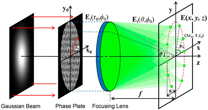
To overcome the focus deviation caused by the axicon phase, we proposed the MFI method, which is accumulated by abundant foci to form the annular amplitude. In theory, the premise of this method is that the annular intensity region is decomposed to obtain an abundant number of diffraction limit foci, and we reverse this process to reconstruct the annular beam. As shown in Figure 1, 10 foci were generated in a circular trajectory. Theoretically, the electric field distribution in the focal region of an aberration-free high-NA objective can be calculated by the Richards–Wolf vectorial diffraction theory [52].
where A is a constant related to the focal length f and the wavelength λ, k = 2π/λ is the wavenumber, (r0, ϕ0) are the polar coordinates of the incident plane, and x, y, and z are the Cartesian coordinates in the focal region. P(θ) is the apodization function of the incident pupil, which can be expressed as
where β = sin−1(NA/nt) is the maximum aperture angle of the objective. θ is the deflection angle, which has the relationship sinθ = r0NA/(R0nt), where R0 is the aperture stop radius, nt is the refractive index behind the objective, and NA is the numerical aperture of the objective lens. Et (θ, ϕ0) is the transmitted field, which has a relationship of the input field, that is
Here, Etx, Ety, and Etz are the components of the Cartesian coordinate system, that is, Et = Etxex + Etyey + Etzez, where ex, ey, and ez are the unit vectors. Eix, Eiy, and Eiz are the polarized components of the incident field Ei, Ei = Eixex + Eiyey + Eizez. In the Debye approximation, the electric field of Eq. 2 can be further expressed as the Fourier transform of the weighted field Et:
where F{·} denotes the Fourier transform (FT). Then, based on the shift theorem of the FT, a phase-only analytical expression for controlling the 2D lateral displacement of the highly focused spot can be given as (17, 53)
where (x0, y0) are the Cartesian coordinates of the incident plane, f = R0nt/NA is the focal length of the objective, and Δxn and Δyn are the shifted displacements of the nth deviated focus versus the original focal center in the focal plane. Based on the phase-only distribution calculated using Eq. 6, the position of the highly focused spots can be controlled in the focal region of a high-NA objective. As shown in Figure 1, the positions of the shifting spots are set along a circular trajectory, the nth focus coordinates Δxn = Rcosφn, Δyn = Rsinφn, φn = 2πn/N, and R is the radius of the circle in the focal plane. Then, we can obtain a superposition field by summing up the finite foci, that is,
Using Eq. 7, multifocal spots along the circular trajectory can be generated. Furthermore, in theory, annular amplitude will be achieved when the number of foci is infinite. After combining a helical phase, a POV with an arbitrary topological charge can be generated. Thus, Eq. 7 can be rewritten as an integral form, that is,
where exp (jlφ) is the helical phase with a topological charge l. Eq. 8 is the key formula of the multi-foci integration (MFI) method to produce the field of the POV. Consequently, when the incident field of the objective lens is modulated by the optical distribution of Eq. 8, the electric field of Eq. 5 in the focal plane can be expressed as
where G (θ, ϕ0) = P(θ) E0 (θ, ϕ0) exp (jkzcosθ)/cosθ, and E0 (θ, ϕ0) indicates the transmitted field when the incident optical field is a plane wave without any phase modulation. Therefore, in this case, the focal field can be expressed as F{G (θ, ϕ0)} = EAiry, which indicates an Airy spot with a diffraction limit size without modulation. The symbol * denotes the convolution operation. Based on the convolution theorem of the Fourier transform, Eq. 9 means that the focal field can be expressed as a convolution of the Airy spot and the Fourier transform of the superposition field calculated by Eq. 8. Then, based on the shift theorem of the Fourier transform, the additional phase shift introduces a linear displacement in the spatial domain, that is, the Fourier transform of the superposition field is
From Eq. 10, we can observe that an ideal annular amplitude with helical phase can be produced when the incident field is modulated by the superposition field. Finally, the electric field of Eq. 9 in the focal plane can be given as
Thus, from Eq. 11, we can observe that an annular amplitude with diffraction limit width and helical phase has been generated by the MFI method. In the experiment, due to the diffraction limit of the focal spot, an annular intensity distribution with a smooth profile can be formed by finite value N (for example, N = 100–200 corresponding to the radius R = 5–10 μm). According to Eq. 2 and Eq. 11, we can observe that a POV with a controllable radius R and topological charge l can be generated in the tightly focused plane through the MFI method.
To verify that the MFI method does not cause the focus deviation, we theoretically simulated the POV intensity distribution in the longitudinal and transverse plane using the axicon phase method and MFI method generated phase pattern, respectively. In this case, we supposed the incident beam is a plane wave, and the simulation parameters are λ = 532 nm, NA = 1.4, nt = 1.518, R = 3.5 μm, and l = 5. When the incident beam is modulated by the axicon phase, the optical field can be expressed as Ui = exp (jkαr + jlφ). Figure 2A shows the simulated results of the axicon phase method with α = 0.065. Thus, the incident field is only modulated by the axicon phase, so the amplitude distribution is a constant, as shown in the top-left of Figure 2A. From Figure 2A, we can observe that the maximum intensity deviates from the focal plane, although the radius of the POV is the same as designed.
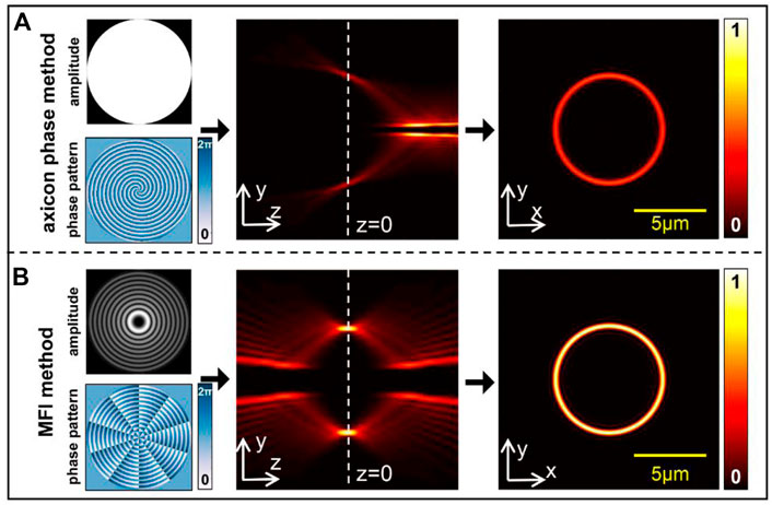
FIGURE 2. Phase pattern, amplitude, and intensity distribution of generated POV by different methods. (A) Axicon phase method. (B) MFI method. Scale bar: 5 μm.
Figure 2B shows the simulated results of the MFI method. It should be noted that the MFI method generates a complex field; thus, the incident field can be modulated by amplitude and phase. As shown in the top-left of Figure 2B, a Bessel amplitude can be generated by the MFI method. In the experiment, we used the complex field encoding method to obtain the phase-only patterns [54]. From Figure 2B, we can observe that the modulated field produced by the MFI method can lead to symmetrical intensity distribution in the focal region. In addition, the desired radius and the maximum intensity distribution of the POV are precisely located at the focal plane. Thus, the MFI method provides an alternative scheme to produce the POV in the tightly focused plane.
Based on the aforementioned calculation, we obtain the POV with the tunable parameter of radius and topological charges in the tightly focused system. Then, we take the superposition of two POVs calculated by the MFI method to obtain the spot array field and possess a controllable phase gradient. The number of spots and phase gradient periods depends on the topological charges of two POVs. To describe the character of the phase gradient of the spot array, we begin with the definition of topological charge. It is defined as a closed path integral of the gradient of the wavefield phase in the transverse plane [21]:
where ζ(·), C, and ∇ are the wavefield phase, closed path around the phase singularity, and vector differential operator, respectively.
The superposition of two POVs can be considered as coaxial interference. Then, the phase of the array at any position on the annular region can be expressed as
Here, the Ph(φ) is the phase distribution in polar coordinate (R, φ) of the focal plane, and mod [Ph(φ),2π] denotes the remainder of the division of Ph(φ) by 2π. Then, the η can be calculated by
In practice, the η can be calculated directly by
where sgn (·) is the signum function, and zero is considered a positive. In addition, the number of spots is γ, and it is calculated by
To generate the spot array field, we take the superposition method using two complex amplitudes of POVs; the transmission function for superposed POVs is
According to Eq. 17, the spot array field can be generated in the tightly focused plane using the MFI method. In Figure 3A, the two methods show similar intensity distribution in the focal plane when there are fewer spots, but in the case of the beam having dozens of spots, the generated array via the axicon phase method is shown to be defocusing with inconstant radius. In contrast, the MFI method maintains the superior focusing property in all situations. In Figures 3B,C, the normalized 3D intensity distribution of 20 spots produced by different methods demonstrates this problem more intuitively. As discussed previously, the issue of deviation caused by the axicon phase still exists, demonstrating that the axicon phase method is not suitable for generating high-order POVs, while the MFI method shows a splendid capability to maintain the focusing property in the tightly focused plane of the superimposed POVs.
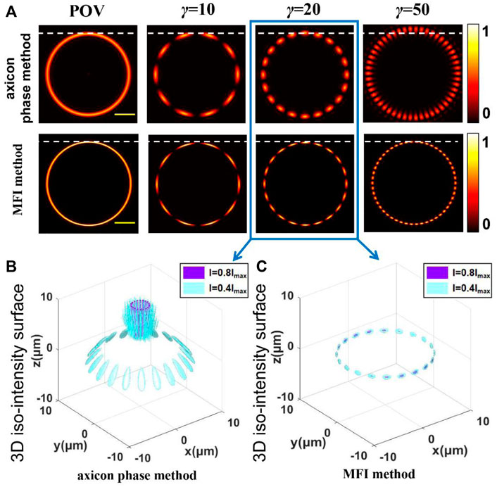
FIGURE 3. (A) Simulated intensity distribution of POV and spot array field in the focal plane produced by the axicon phase method and MFI method. (B,C) Simulation result of the normalized 3D intensity distribution of 20 spots produced by different methods. Scale bar: 4 μm.
Except that perfect focusing property in the tightly focused plane, the spot array field has a tunable phase gradient. We envision that the intensity gradient and phase gradient forces are competitive [55], that is, more spots lead to affect the orbital transport (driven by the phase gradient). In the case that η < γ (meaning that the number of spots is greater than the total phase gradient periods), it will show the decomposition of phase gradient in the spot array field. As shown in Figure 4A, when η = 0 and γ = 50, the phase is decomposed to 3π/2 and π/2, respectively. When the total periods of phase gradient η = 10 in Figure 4B (l1 = 30 and l2 = -20), each of the same phases of spots is repeated 10 times, and the 10 periods of 0∼2π will be evenly decomposed into 50 spots. Each period occupies five spots, and they were mutually crosswise; the phase distribution cannot be continuous. However, the red dotted line in Figure 4B shows the phase continuity of five spots, even though one period of the phase gradient is decomposed. Such multiple spots with phase step profiles is more beneficial to capture particles.
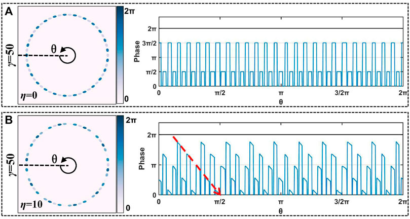
FIGURE 4. Simulation results of decomposed phase distribution in 50 spots with different total phase gradient periods. (A) η = 0, (B) η = 10.
In addition, when there are few spots in the array, they will have stripe-shaped profiles. Here, we demonstrate the diagram of the superposition method and take γ = 2 as an example. In Figure 5A, the figures with purple edges indicate that the topological charges of superposed POVs are l1 = 1 and l2 = −1, and the red edge figures mean l1 = 3 and l2 = 5. It shows that when η > γ, each stripe-shaped focus carries more than one phase gradient period. Moreover, the different phase gradients do not affect the intensity of the spot array. We define m to represent the phase gradient periods carried by the spot array since the noncontinuous intensity distribution in the original annular region cannot carry the total topological charge. In Figure 5B, the intensity and phase distribution of the spot array are given; the first and second columns show the phase distribution corresponding to the procedure marked in purple, and the fourth and fifth columns correspond to the red-marked procedure. ηL, ηR, mL, and mR are the left and right half-section of η and m. The phase in some positions is not jumped from 0 to 2π but from 3π/2 to π/2; the phase jump location is marked by the red line in the line chart of Figure 5B. Due to the phase start location of two superposed POVs being in different azimuthal positions, the position difference is π (it also can explain the line chart in Figure 4A). To obtain the designed phase gradient of the spot array, appropriate topological charges should be chosen. From the competition of intensity- and phase-gradient forces, this has great significance for the arbitrary selection of phase-gradient forces to manipulate micro-objects on stripe-shaped spot fields.
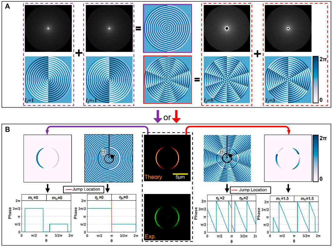
FIGURE 5. (A) Superposition process diagram. (B) Corresponding intensity and phase distribution in the focal plane. Scale bar: 5 μm.
Experimental Results
We perform the optical imaging experiment with our homemade setup shown schematically in Figure 6. The beam with a wavelength of 532 nm (LWGL532, Beijing Laserwave Optoelectronics Technology Co., Ltd., China) is expanded and collimated onto a spatial light modulator (Pluto2-NIR-011, HOLOEYE Photonics AG, Germany) and then relayed to the back-aperture plane of a ×100 magnification, NA = 1.4 oil immersion objective (UPlanSApo ×100, Olympus, Japan), using a 4f filter system. The LED lighting source is used to illuminate the microparticle-trapping plane. A CCD (EO-5012, Edmund Optics, US) camera is utilized to record the images of the focal spots and the trapping particles.
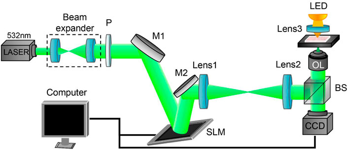
FIGURE 6. Schematic of the experimental configuration. P: polarizer; BS: beam splitter; M: mirror; SLM: spatial light modulator; OL: objective lens.
The spot array field produced by the superposition of two POVs maintains the focusing property in the tightly focused plane as the spot number increases, as shown in Figure 7A. It has an application value to improve the efficiency of optical imaging, micromanipulation, direct laser writing, etc. In Figure 7B, we produced 100 spots, and l1 and l2 were chosen to be ±50 (the maximum spot number γmax is limited by the radius of the array, see Supplementary Material). The experimental results substantiate that the high order spot array can be achieved and observed (here, the order of spot array is equal to the spot number). It is one particular advantage of the spot array based on the MFI method.
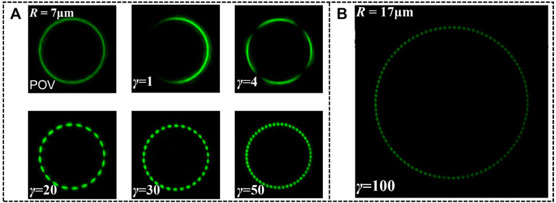
FIGURE 7. (A) Experimental contrast of intensity distribution of POV and spot array. (B) Intensity distribution of high-order spot array with 100 spots.
A spot array field carrying arbitrary orbital angular momentum should have the capability to manipulate the microparticle. In the following optical trapping experiment, silica beads with a diameter of 1 μm, dispersed in deionized water within a glass chamber (100 μm thickness), are applied as the sample for trapping. As shown in Figure 8A, we can observe the intensity and phase distribution of the spot array with 20 spots (R = 8μm, η = 0, topological charges of superposed POVs l1 = 10 and l2 = −10) in the focal plane. This spot array field with multi-spot intensity distribution could capture the particles steadily; the corresponding experiment snapshots are shown in Figure 8B.
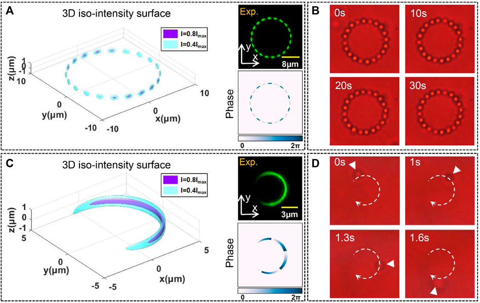
FIGURE 8. (A,C) Intensity and phase distribution of spot array in the focal region. (B,D) Corresponding trapping snapshots.
As the spot number decreases, the phase gradient force could contribute more to the time-averaged optical force acting on a particle. The field with one spot (R = 3μm, η = 5.5, m = 4, l1 = 6 and l2 = 4) is chosen to achieve the orbital transportation; the intensity and phase distribution in the focal region are shown in Figure 8C. The snapshots of the experiment in Figure 8D show that one silica particle was moving along the orbital-shaped spot, which was then released rapidly (see Video 2). This unique orbital-shaped spot may have a significant contribution to the application of particle sorting [56, 57]and optical storage [58, 59]. Moreover, more types of spot array beams with different parameters were used to investigate the effects of different experimental parameters on trapping (for more experimental details, see Supplementary Material). The stabilization and dynamic manipulation in the tightly focused plane indicate that the spot array field has independent controllable multiple parameters with radius, number of spots, and phase gradient, greatly expanding the degree of freedom of focusing vortex beams.
Discussion
In this study, we have presented and demonstrated the MFI method for generating POV in the focal plane of tightly focused systems. By creating a finite number of diffraction limit foci at the focal plane, we formed the annular ring with arbitrary radius and combined the helical phase to construct a POV. Subsequently, we took the superposition procedure of two POVs and created a spot array in the focal plane. The independent multiple parameters of spot arrays include radius, number of spots, and distribution of phase gradient. In particular, in the superposition of high-order beams, we also produced a 100-order array, which has no deviation and maintains a clear profile in the focal region. In the further trapping experiment, the behavior of trapped particles showed that the spot array has more “perfect” focusing properties than the traditional superposed Bessel beams. Such a complicated vortex beam with a dynamically controlled structure and phase gradient providing a novel optical field deepened the research into the orbital angular momentum communication, fast femtosecond two-photon polymerization, micromanipulation, and optical momentum measurement.
Data Availability Statement
The original contributions presented in the study are included in the article/Supplementary Material, further inquiries can be directed to the corresponding authors.
Author Contributions
MS, QS, and XJ contributed to conception and design of the study. XJ and LZ organized the database. XJ and YT performed the experiment. XJ wrote the first draft of the manuscript. ZL, DZ, and KC gave suggestions in numerical simulations. All authors contributed to the revision of the manuscript and approved the final version.
Funding
This work was supported by the National Natural Science Foundation of China (62174073 and 61675093), the Key Research and Development Project of Shandong Province (2019JZZY020219), and the Program of Science and Technology Development of Yantai (2020XDRH095).
Conflict of Interest
QS was employed by Yantai Magie Nano-Technology Co. Ltd.
The remaining authors declare that the research was conducted in the absence of any commercial or financial relationships that could be construed as a potential conflict of interest.
Publisher’s Note
All claims expressed in this article are solely those of the authors and do not necessarily represent those of their affiliated organizations, or those of the publisher, the editors, and the reviewers. Any product that may be evaluated in this article, or claim that may be made by its manufacturer, is not guaranteed or endorsed by the publisher.
Supplementary Material
The Supplementary Material for this article can be found online at: https://www.frontiersin.org/articles/10.3389/fphy.2022.879689/full#supplementary-material
References
1. Allen L., Beijersbergen M. W., Spreeuw R. J. C., Woerdman J. P. Orbital Angular Momentum of Light and the Transformation of Laguerre-Gaussian Laser Modes. Phys Rev A (1992) 45(11):8185–8189. doi:10.1103/physreva.45.8185
2. Roichman Y., Sun B., Roichman Y., Amato-Grill J., Grier D. G. Optical Forces Arising from Phase Gradients. Phys Rev Lett (2008) 100(1):013602. doi:10.1103/PhysRevLett.100.013602
3. Dennis M. R., O'Holleran K., Padgett M. J. Chapter 5 Singular Optics: Optical Vortices and Polarization Singularities. Progress Opt (2009) 53, 293–363. doi:10.1016/s0079-6638(08)00205-9
4. Gibson G., Courtial J., Padgett M. J., Vasnetsov M., Pas'ko V., Barnett S. M, et al. Free-Space Information Transfer Using Light Beams Carrying Orbital Angular Momentum. Opt Express (2004) 12(22):5448–56. doi:10.1364/OPEX.12.005448
5. Kotlyar V. V., Kovalev A. A., Porfirev A. P. An Optical Tweezer in Asymmetrical Vortex Bessel-Gaussian Beams. J Appl Phys (2016) 120(2):023101. doi:10.1063/1.4958309
6. Chen M, Mazilu M, Arita Y, Wright EM, Dholakia K. Optical Trapping with a Perfect Vortex Beam. In: Proceedings of SPIE - The International Society for Optical Engineering (2014). doi:10.1117/12.2064080
7. Chen M., Mazilu M., Arita Y., Wright E. M., Dholakia K. Creating and Probing of a Perfect Vortex In Situ with an Optically Trapped Particle. Opt Rev (2015) 22(1):162–165. doi:10.1007/s10043-015-0031-7
8. Chen M., Mazilu M., Arita Y., Wright E. M., Dholakia K. Dynamics of Microparticles Trapped in a Perfect Vortex Beam Opt Lett (2013) 38(22):4919–22. doi:10.1364/OL.38.004919
9. Ni J., Wang C., Zhang C., Hu Y., Yang L., Lao Z, et al. Three-Dimensional Chiral Microstructures Fabricated by Structured Optical Vortices in Isotropic Material. Light Sci Appl (2017) 6(7):e17011. doi:10.1038/lsa.2017.11
10. Yang L., Chen X., Wang L., Hu Z., Xin C., Hippler M, et al. Targeted Single‐Cell Therapeutics with Magnetic Tubular Micromotor by One‐Step Exposure of Structured Femtosecond Optical Vortices. Adv Funct Mater (2019) 29(45):1905745. doi:10.1002/adfm.201905745
11. Yang L., Qian D., Xin C., Hu Z., Ji S., Wu D, et al. Direct Laser Writing of Complex Microtubes Using Femtosecond Vortex Beams. Appl Phys Lett (2017) 110(22):221103. doi:10.1063/1.4984744
12. Hu Z-Y., Tian Z-N., Hua J-G., Chen Q-D., Sun H-B. Axially Controllable Multiple Orbital Angular Momentum Beam Generator. Appl Phys Lett (2020) 117(2):021101. doi:10.1063/5.0011445
13. Qin F., Liu B., Zhu L., Lei J., Fang W., Hu D, et al. π-Phase Modulated Monolayer Supercritical Lens. Nat Commun (2021) 12(1):32. doi:10.1038/s41467-020-20278-x
14. Jiang M., Song S., Li Y., Zeng X., Zhu L., Zhang M, et al. 3d High Precision Laser Printing of a Flat Nanofocalizer for Subwavelength Light Spot Array. Opt Lett (2021) 46(2):356–9. doi:10.1364/OL.413302
15. Zhu L., Yu J., Zhang D., Sun M., Chen J. Multifocal Spot Array Generated by Fractional Talbot Effect Phase-Only Modulation. Opt Express (2014) 22(8):9798–808. doi:10.1364/OE.22.009798
16. Zhu L., Sun M., Zhu M., Chen J., Gao X., Ma W, et al. Three-Dimensional Shape-Controllable Focal Spot Array Created by Focusing Vortex Beams Modulated by Multi-Value Pure-phase Grating. Opt Express (2014) 22(18):21354–67. doi:10.1364/oe.22.021354
17. Zhu L., Sun M., Zhang D., Yu J., Wen J., Chen J. Multifocal Array with Controllable Polarization in Each Focal Spot. Opt Express (2015) 23(19):24688–98. doi:10.1364/oe.23.024688
18. Yu J., Zhou C., Jia W., Hu A., Cao W., Wu J, et al. Three-Dimensional Dammann Vortex Array with Tunable Topological Charge. Appl Opt (2012) 51(13):2485. doi:10.1364/AO.51.002485
19. Yu J., Zhou C., Lu Y., Wu J., Zhu L., Jia W. Square Lattices of Quasi-Perfect Optical Vortices Generated by Two-Dimensional Encoding Continuous-phase Gratings. Opt Lett (2015) 40(11):2513–6. doi:10.1364/OL.40.002513
20. Li X., Ma H., Yin C., Tang J., Li H., Tang M, et al. Controllable Mode Transformation in Perfect Optical Vortices. Opt Express (2018) 26(2):651–62. doi:10.1364/OE.26.000651
21. Ma H., Li X., Zhang H., Tang J., Li H., Tang M, et al. Optical Vortex Shaping via a Phase Jump Factor. Opt Lett (2019) 44(6):1379–82. doi:10.1364/OL.44.001379
22. Zhang H., Li X., Ma H., Tang M., Li H., Tang J, et al. Grafted Optical Vortex with Controllable Orbital Angular Momentum Distribution. Opt Express (2019) 27(16):22930–8. doi:10.1364/OE.27.022930
23. Ostrovsky A. S., Rickenstorff-Parrao C., Arrizón V. Generation of the "Perfect" Optical Vortex Using a Liquid-Crystal Spatial Light Modulator. Opt Lett (2013) 38(4):534–6. doi:10.1364/OL.38.000534
24. Andrews DL, Roichman Y, Galvez EJ, Grier DG, Nienhuis G. Three-Dimensional Holographic Ring Traps. Complex Light and Optical Forces. In: Proceedings of SPIE - The International Society for Optical Engineering (2007). doi:10.1117/12.701034
25. Vaity P., Rusch L. Perfect Vortex Beam: Fourier Transformation of a Bessel Beam. Opt Lett (2015) 40(4):597–600. doi:10.1364/OL.40.000597
26. Chen Y., Fang Z-X., Ren Y-X., Gong L., Lu R-D. Generation and Characterization of a Perfect Vortex Beam with a Large Topological Charge through a Digital Micromirror Device. Appl Opt (2015) 54(27):8030–5. doi:10.1364/AO.54.008030
27. Liu X., Li Y., Han Y., Deng D., Zhu D. High Order Perfect Optical Vortex Shaping. Opt Commun (2019) 435:93–96. doi:10.1016/j.optcom.2018.11.029
28. Chen Y., Wang J., Wang C., Zhang S., Cao M., Franke-Arnold S, et al. Phase Gradient Protection of Stored Spatially Multimode Perfect Optical Vortex Beams in a Diffused Rubidium Vapor. Opt Express (2021) 29(20):31582–93. doi:10.1364/OE.439716
29. Zheng S., Wang J. Measuring Orbital Angular Momentum (Oam) States of Vortex Beams with Annular Gratings. Sci Rep (2017) 7:40781. doi:10.1038/srep40781
30. Xie G., Song H., Zhao Z., Milione G., Ren Y., Liu C, et al. Using a Complex Optical Orbital-Angular-Momentum Spectrum to Measure Object Parameters. Opt Lett (2017) 42(21):4482–5. doi:10.1364/OL.42.004482
31. Litvin I. A., Dudley A., Forbes A. Poynting Vector and Orbital Angular Momentum Density of Superpositions of Bessel Beams. Opt Express (2011) 19(18):16760–71. doi:10.1364/OE.19.016760
32. Vasilyeu R., Dudley A., Khilo N., Forbes A. Generating Superpositions of Higher-Order Bessel Beams. Opt Express (2009) 17(26):23389–95. doi:10.1364/OE.17.023389
33. Yang L., Qian D., Xin C., Hu Z., Ji S., Wu D, et al. Two-Photon Polymerization of Microstructures by a Non-diffraction Multifoci Pattern Generated from a Superposed Bessel Beam. Opt Lett (2017) 42(4):743–6. doi:10.1364/OL.42.000743
34. Khonina S. N., Kazanskiy N. L., Khorin P. A., Butt M. A. Modern Types of Axicons: New Functions and Applications. Sensors (2021) 21(19):6690. doi:10.3390/s21196690
35. Jaroszewicz Z, Burvall A, Friberg AT. Axicon - the Most Important Optical Element. Opt Photon News (2005) 16(4). doi:10.1364/opn.16.4.000034
36. Mcleod JH. The Axicon : A New Type of Optical Element. J Opt Soc Am (1954) 44. doi:10.1364/josa.44.000592
37. Khonina S. N., Porfirev A. P. 3d Transformations of Light Fields in the Focal Region Implemented by Diffractive Axicons. Appl Phys B (2018) 124(9). doi:10.1007/s00340-018-7060-4
38. Khonina S. N., Kazanskiĭ N. L., Ustinov A. V., Volotovskiĭ S. G. The Lensacon: Nonparaxial Effects. J Opt Technol (2011) 78(11):724–9. doi:10.1364/JOT.78.000724
39. Khonina S. N., Kotlyar V. V., Skidanov R. V., Soifer V. A., Jefimovs K., Simonen J, et al. Rotation of Microparticles with Bessel Beams Generated by Diffractive Elements. J Mod Opt (2004) 51(14):2167–2184. doi:10.1080/09500340408232521
40. Vasara A., Turunen J., Friberg A. T. Realization of General Nondiffracting Beams with Computer-Generated Holograms. J Opt Soc Am A (1989) 6(11):1748–54. doi:10.1364/josaa.6.001748
41. Jiménez-Gambín S., Jiménez N., Benlloch J. M., Camarena F. Generating Bessel Beams with Broad Depth-Of-Field by Using Phase-Only Acoustic Holograms. Sci Rep (2019) 9(1):20104. doi:10.1038/s41598-019-56369-z
43. McGloin D., Dholakia K. Bessel Beams: Diffraction in a New Light. Contemp Phys (2005) 46(1):15–28. doi:10.1080/0010751042000275259
44. López-Aguayo S., Kartashov Y. V., Vysloukh V. A., Torner L. Method to Generate Complex Quasinondiffracting Optical Lattices. Phys Rev Lett (2010) 105(1):013902. doi:10.1103/PhysRevLett.105.013902
45. Durnin J. Exact Solutions for Nondiffracting Beams I the Scalar Theory. J Opt Soc Am A (1987) 4(4):651–4. doi:10.1364/josaa.4.000651
46. Topuzoski S. Generation of Optical Vortices with Curved Fork-Shaped Holograms. Opt Quant Electron (2016) 48(2). doi:10.1007/s11082-016-0405-5
47. Khonina S. N., Ustinov A. V., Kirilenko M. S., Kuchmizhak A. A., Porfirev A. P. Application of a Binary Curved Fork Grating for the Generation and Detection of Optical Vortices outside the Focal Plane. J Opt Soc Am B (2020) 37(6):1714–21. doi:10.1364/josab.388431
48. Zhang C., Hu Y., Li J., Li G., Chu J., Huang W. A Rapid Two-Photon Fabrication of Tube Array Using an Annular Fresnel Lens. Opt Express (2014) 22(4):3983–90. doi:10.1364/OE.22.003983
49. Descour M. R., Simon D. I., Yeh W-H. Ring-Toric Lens for Focus-Error Sensing in Optical Data Storage. Appl Opt (1999) 38(8):1388–92. doi:10.1364/ao.38.001388
50. Khonina S. N., Kharitonov S. I., Volotovskiy S. G., Soifer V. A. Caustics of Non-paraxial Perfect Optical Vortices Generated by Toroidal Vortex Lenses. Photonics (2021) 8(7):259. doi:10.3390/photonics8070259
51. Kotlyar V. V., Kovalev A. A., Porfirev A. P. Optimal Phase Element for Generating a Perfect Optical Vortex. J Opt Soc Am A (2016) 33(12):2376–84. doi:10.1364/JOSAA.33.002376
52. Richards B, Wolf E. Electromagnetic Diffraction in Optical Systems. Ii. Structure of the Image Field in an Aplanatic System. Proc R Soc, Ser A (1959) 253:358–79.
53. Zhu L., Yang R., Zhang D., Yu J., Chen J. Dynamic Three-Dimensional Multifocal Spots in High Numerical-Aperture Objectives. Opt Express (2017) 25(20):24756–66. doi:10.1364/OE.25.024756
54. Mendoza-Yero O., Mínguez-Vega G., Lancis J. Encoding Complex Fields by Using a Phase-Only Optical Element. Opt Lett (2014) 39(7):1740–3. doi:10.1364/ol.39.001740
55. Nan F., Yan Z. Synergy of Intensity, Phase, and Polarization Enables Versatile Optical Nanomanipulation. Nano Lett (2020) 20(4):2778–2783. doi:10.1021/acs.nanolett.0c00443
56. Wu W., Zhu X., Zuo Y., Liang L., Zhang S., Zhang X, et al. Precise Sorting of Gold Nanoparticles in a Flowing System. ACS Photon (2016) 3(12):2497–2504. doi:10.1021/acsphotonics.6b00737
57. Nan F., Yan Z. Optical Sorting at the Single-Particle Level with Single-Nanometer Precision Using Coordinated Intensity and Phase Gradient Forces. ACS Nano (2020) 14(6):7602–7609. doi:10.1021/acsnano.0c03478
58. Zhu L., Cao Y, Cao Y., Chen Q., Ouyang X., Xu Y, et al. Near-Perfect Fidelity Polarization-Encoded Multilayer Optical Data Storage Based on Aligned Gold Nanorods. Oea (2021) 4(11):210002. doi:10.29026/oea.2021.210002
Keywords: perfect optical vortex, orbital angular momentum, interference superposition, spatial light modulator, optical manipulation
Citation: Jiang X, Tian Y, Sun M, Li Z, Zhang D, Cao K, Shi Q and Zhu L (2022) Perfect Optical Vortex to Produce Controllable Spot Array. Front. Phys. 10:879689. doi: 10.3389/fphy.2022.879689
Received: 20 February 2022; Accepted: 29 March 2022;
Published: 09 May 2022.
Edited by:
Gianluca Ruffato, University of Padua, ItalyReviewed by:
Svetlana Khonina, Image Processing Systems Institute, RussiaMingzhou Chen, University of St Andrews, United Kingdom
Copyright © 2022 Jiang, Tian, Sun, Li, Zhang, Cao, Shi and Zhu. This is an open-access article distributed under the terms of the Creative Commons Attribution License (CC BY). The use, distribution or reproduction in other forums is permitted, provided the original author(s) and the copyright owner(s) are credited and that the original publication in this journal is cited, in accordance with accepted academic practice. No use, distribution or reproduction is permitted which does not comply with these terms.
*Correspondence: Meiyu Sun, cy5tLnkuMjAwOEAxNjMuY29t; Qiang Shi, c2hpLnFpYW5nQG1hZ2llLW5hbm8uY29t
 Xiaotong Jiang
 Yuyuan Tian
 Meiyu Sun
 Zhigang Li
 Dengying Zhang
 Kunjian Cao
 Qiang Shi
 Linwei Zhu