
94% of researchers rate our articles as excellent or good
Learn more about the work of our research integrity team to safeguard the quality of each article we publish.
Find out more
ORIGINAL RESEARCH article
Front. Phys., 29 March 2022
Sec. Optics and Photonics
Volume 10 - 2022 | https://doi.org/10.3389/fphy.2022.877804
This article is part of the Research TopicLaser Field Manipulation and Its Advanced ApplicationsView all 8 articles
Optical sorting, as one kind of optical tweezers, is used to separate mixed particles in a background environment. This unusual tool has a wide application prospect because the non-contact and non-destructive advantages ideally suit the pressing need of bio-technology. However, most sorting methods and devices have been accomplished based on real-time one-by-one sorting, which ignored the sorting efficiency and is not applicable to high-capacity particles. Although more and more structured light beams are proposed to enhance the sorting efficiency, it is still not enough for desired applications. Here, we propose a method for the massive parallel sorting of particles: polygonal optical vortex (OV) beams are unwound by a geometric transformation to produce linear OV beams with kinked distributions. This structured light is used to greatly enhance the sorting efficiency. We adopt the fractal theory to illustrate the increase of the region over which the beam can interact with particles. We demonstrate that the gradient force of this beam is large enough to manipulate spherical particles in the Rayleigh regime of scattering. These results introduce new possibilities for high-capacity particle sorting.
For decades, optical tweezers have been used to sort cells in a fluid environment [1, 2]. Tweezers use a single focused beam to trap and manipulate high-refractive-index particles [3]; the technique was a natural evolution of the early work of Ashkin using dual beams for trapping [4]. Optical tweezers are an ideal tool for micromanipulation because they are non-contact and non-destructive; therefore, they are widely used in life sciences [5], biology [6], biophysics [7], and colloidal sciences [8, 9].
In practice, many varieties of optical tweezers have been realized [10–16], such as plasmonic tweezers [10], non-linear tweezers [11], vortex tweezers [12, 13], optical trap arrays [14–16], and more [17–21]. But single function tweezers designed to trap an object cannot satisfy all desired tasks [12, 22–28], such as the transportation [12], micromachining [22], and sorting [23–27] of multiple particles.
Mixed particles in a background environment can be separated by optical sorting [1, 2, 29]. Optical sorting selects target particles from a mixed distribution of particles using their differing responses to optical forces [16, 23–27, 30, 31]. Microscopic particles are sorted by an optical lattice, which has a high sorting efficiency [16]. Living and dead cells have been massively parallel separated by optical imaging, with live cells trapped in an optical ring [24]. Yeast cells of different sizes have been effectively separated and transported by dual-channel line optical tweezers [30]. The Junin virus particles were successfully sorted based on the light scattering parameters of fluorescent channels, which also can compare particles secreted by virus and human primary macrophages [27]. Nanoscale particles with sizes from 20 to 110 nm have been separated by nanoscale deterministic lateral displacement arrays [25]. Soft particles can be sorted from rigid particles using a microfluidic device, which can realize real-time one-by-one sorting and a sorting purity of 88% [26]. Although some devices have been made that can enhance the sorting efficiency [23, 24, 30, 31], it is often not enough for desired applications.
Beams with vortex structures have been shown to be quite versatile in trapping applications, both in the trapping of low-index particles [32] and in the rotation of particles [33]. Optical vortex (OV) beams have an azimuthal phase factor exp(ilθ), where θ denotes the azimuth angle and l is an integer known as the topological charge. Traditional vortex beams are symmetric around their central axis [34–37]; modulated vortex beams with a specific polygon shape can be generated by manipulating the vortex phase function, and the utility of such beams in optical manipulation has been demonstrated experimentally [38, 39]. An OV beam can be transformed into a linear intensity distribution by a geometric transformation, and this is now a standard method to spatially sort beams with different topological charges [40]. Laguerre–Gaussian (LG) beams are the archetypical class of OV beams [41].
In this paper, we modulate an LG beam to obtain a linear OV beam with a kinked distribution to realize massively parallel sorting of particles. The kinked distribution increases the size of the region in which the particles interact with light, significantly improving the sorting capabilities of the system.
The field of an OV beam of radial order n and azimuthal order l in the waist plane may be written as
where (ρ, θ) are polar coordinates, Anl(ρ) represents the amplitude of the beam, and exp (ilθ) is the vortex phase term with topological charge l [41]. The intensity distribution is the number of circular rings equal to the order n + 1.
If one replaces the vortex phase with a term exp[iϕ(θ)], then the shape of the OV beam is determined by the function ϕ(θ) [38]. A polygon OV beam can be generated in the far field by manipulating the function ϕ(θ) of an LG beam with radial order n = 0. Then, the field can be expressed as follows:
where A0 is a constant and w denotes the beam width. The phase ϕ(θ) is written as
with
where b is a constant, R(φ) is the mathematical expression for the side of a convex polygon, and (ri, φi) represents the polar coordinates of the vertices of the polygon. For simplicity, the starting vertex (r1, φ1) is fixed at φ = 0. The geometric distribution of the intensity can be designed by modulating the piecewise function R(φ).
By sending a polygon OV beam through the aforementioned geometric transformer, we can unwind it into a linear OV beam; the corners of the polygon are mapped into kinks in the linear beam. The transformation phase function is [40, 42]
and the output field is
where (x, y), (u, v) are the Cartesian coordinates in the polygon OV field and the Fourier plane, respectively. U(u, v) is the electric field of the linear OV beam with a kinked distribution, and f denotes the focal length of the lens. Here, a1 and a2 are independent constants which determine the size and the position of the transformed field. Figure 1 displays the intensity distributions of the input and linear OV beams with parameters f = 50mm, w = 0.1mm, l = 25, b = −0.4 × l, 2πa1 = 1mm, and a2 = 4.5 mm.
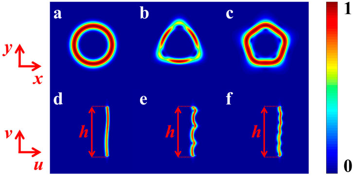
FIGURE 1. Intensity distribution of polygon OV beams: (A) circular, (B) triangle, and (C) pentagon. (D–F) Linear OV beams with kinked distribution corresponding to (A–C).
Applying Eqs 2–4, the shapes of polygon OV beams are chosen as circular, triangular, and pentagonal (see Figures 1A–C); the corresponding unwound intensity distributions of the linear OV beams can be seen in Figures 1D–F. They all have the same extension h in the v direction. Figure 1D is a beam without kinks; Figure 1E and Figure 1F are beams with the intensity distribution carrying kinks. It is obvious that the kinks are related to the shape of the polygonal OV beams. We use these beams to enhance the efficiency in particle sorting.
Based on the fractal theory, the kinked profile of the intensity pattern is a non-rectifiable curve [43, 44]. Cut the curve into N integer segments (N > 1), and the fractal dimension D can be expressed as D = − ln N/ln r(N), where r(N) is the similarity ratio [43]. The length of the curve for Figure 1 is defined as L = hN1−1/D. D will be more accurate with the smaller value of r(N), and the length L will be longer. In Figures 1D–F, the fractal dimension D is determined by the kinks (see Figure 1E and Figure 1F). The linear OV beam with kinked distribution satisfies D > 1; as a result, L is larger than h. To the same extent h, the more the kinks are, the longer the L will be. Therefore, the length of the pattern in Figure 1F is the longest compared to that in Figure 1D and Figure 1E.
Because of the kinks, the length of the intensity pattern is longer than the spatial extent h of the beam, increasing the region over which the beam can interact with particles. This enhancement can be used in particle sorting to enhance the sorting efficiency.
In the sorting platform, two kinds of particles with different refractive indices are mixed in a fluid environment. For example, the power
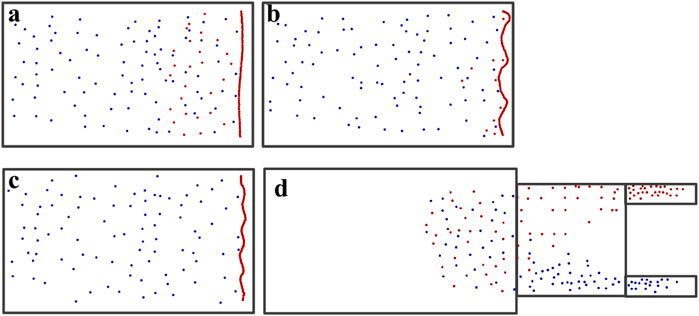
FIGURE 2. Particles with a higher refractive index (red spheres) and lower refractive index (blue spheres) are sorted by the optical sorting platform. A linear OV beam (A) without kinks (see Supplementary Movie S1), (B) with kinks corresponding to a triangle (see Supplementary Movie S2), and (C) with kinks corresponding to a pentagon (see Supplementary Movie S3). (D) Optical lattice (see Supplementary Movie S4).
To analyze the sorting capacity of the generated beam, we consider the force acting on the particles. The radiation force consists of the scattering force Fscat and the gradient force Fgrad. According to the theory of Rayleigh scattering, when the radius of a spherical nanoparticle a ≪ λ, the two kinds of forces can be calculated separately [45]. In order to stably manipulate particles, Fgrad is supposed to be large enough to overcome Fscat. The buoyancy, gravity, and Brownian forces can be neglected by decreasing temperature and increasing light intensity [46]. The expressions of the gradient force Fgrad and scatter force Fscat are
where I = |U(u, v)|2 is the intensity of the focused beam, a represents the particle size, c is the light speed, and m = np/nm, in which nm, np are the refractive indices of the environment and the Rayleigh particles, respectively. We calculate the gradient force and the scatter force in the horizontal direction (v = 0). Figure 3 shows the radiation forces of the particles in a linear OV beam without kinks (see Figure 3A1, Figure 3B1), with kinks corresponding to a triangle (see Figure 3A2, Figure 3B2) and a pentagon (see Figure 3A3, Figure 3B3). The red and blue curves represent the radiation force of particles with higher and lower refractive indices, respectively. Comparing the three cases, as the kinks increase, the maximum value of the radiation forces is slightly different. By comparing Figure 3A with Figure 3B, it is obvious that the gradient force Fgrad is about 10 orders of magnitude larger than the scatter force Fscat in each case. From Figure 3B, one can see that the direction of the gradient force Fgrad of the two kinds of particles is different. The sign of the gradient force Fgrad denotes the direction of the force. The positive Fgrad represents that the gradient force is along the positive u direction, and the negative value represents that the force is along the negative u direction. In Figure 3B, there is only one stable equilibrium point for the particles with high refractive index, which is marked by a solid black dot. Therefore, only the particles with a higher refractive index can be stably manipulated. This theoretical analysis demonstrates that only the particles with a higher refractive index can move with the unwound polygonal OV beam.
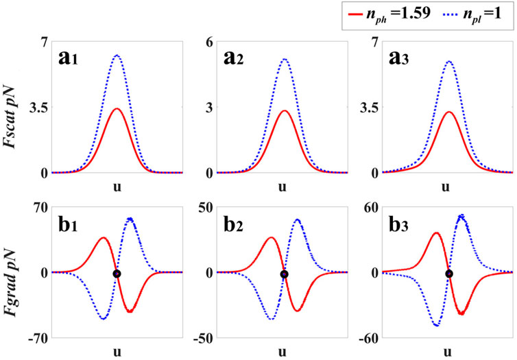
FIGURE 3. Radiation forces of the two kinds of particles in linear OV beams. The blue dashed lines and the red solid lines represent the particles with low and high refractive indices, respectively. (A1–A3) Scattering force with different numbers of kinks. (B1–B3) Gradient force with different numbers of kinks.
We give the simulation analysis of the microfluidic sorting system [16]. We use the Gaussian beam with the beam waist size w = 0.1 mm, the power
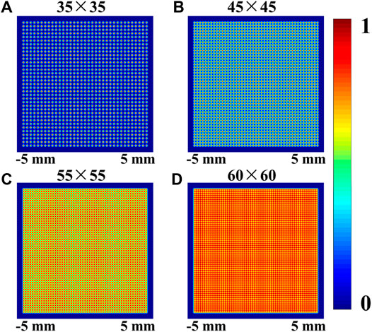
FIGURE 4. Intensity distribution of the Gaussian lattice with the same beam size and different numbers of arrays. (A) 35×35 array; (B) 45×45 array; (C) 55×55 array; (D) 60×60 array.
From the above analysis, it is obvious that the space interval of the adjacent array needs to be sufficient to stably trap particles. Therefore, we simulate the Gaussian lattice with different arrays when the order of magnitude m is about 10 (see Figure 6). One can see that the beam size increases with the increasing number of arrays. In Ref. [16], the sorting path of particles combines the length of the sorting platform and the beam size. Therefore, the beam size plays an important role in sorting time. The larger the beam size, the more the sorting time. In Figure 7, we display the sorting time in an optical lattice with different numbers of arrays when the speed is 2 mm/s and the length of the platform is 5 mm. It is obvious that more arrays bring more sorting time. In contrast, in our strategy, the sorting path is just the length of the sorting platform. Thus, we added the blue dashed line to represent the sorting time in our strategy. It is obvious that our strategy can save sorting time of particles. In Supplementary Movie S4, it can be seen that the sorting efficiency of the lattice is much less than that of the unwound OV beams (see Figure 2D). In other words, we can sort more particles in the same time than the strategy proposed by M. P. MacDonald.
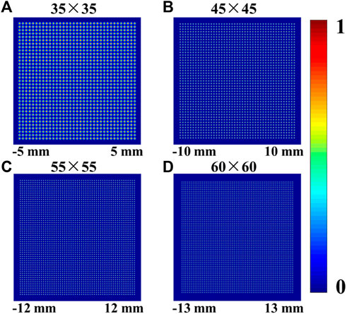
FIGURE 6. Intensity distribution of the Gaussian lattice with different numbers of arrays. (A) 35×35 array; (B) 45×45 array; (C) 55×55 array; (D) 60×60 array.
In conclusion, through the use of unwound polygonal OV beams, we propose a new method for massively parallel sorting. Such unwound polygonal OV beams can be generated by a geometric transformation. The sorting area is greatly enlarged, and the sorting efficiency is enhanced by increasing the region in which the light and particles interact. Our results are of significant interest to researchers engaged in high-capacity particle sorting in many disciplines, such as biomedical science and colloid physics.
The original contributions presented in the study are included in the article/Supplementary Material, and further inquiries can be directed to the corresponding authors.
YC and YY conceptualized the idea and designed the methodology. XL carried out the methodology and wrote the original draft. XL, HZ, and YG were involved in the formal analysis. GG, YC, and YY polished the manuscript. All authors read and approved the final manuscript.
This work was supported by the National Key Research and Development Program of China (2019YFA0705000), National Natural Science Foundation of China (NSFC) (Nos. 91750201, 12192254, 11974219, 11974218, 12174227, 91950104), Innovation Group of Jinan (2018GXRC010), Natural Science Foundation of Shandong Provincial (ZR2019MA028), and Local Science and Technology Development Project of the Central Government (YDZX20203700001766).
The authors declare that the research was conducted in the absence of any commercial or financial relationships that could be construed as a potential conflict of interest.
All claims expressed in this article are solely those of the authors and do not necessarily represent those of their affiliated organizations, or those of the publisher, the editors, and the reviewers. Any product that may be evaluated in this article, or claim that may be made by its manufacturer, is not guaranteed or endorsed by the publisher.
The Supplementary Material for this article can be found online at: https://www.frontiersin.org/articles/10.3389/fphy.2022.877804/full#supplementary-material
1. Enger J, Goksör M, Ramser K, Hagberg P, Hanstorp D. Optical Tweezers Applied to a Microfluidic System. Lab Chip (2004) 4:196–200. doi:10.1039/b307960k
2. Zhang H, Liu K-K. Optical Tweezers for Single Cells. J R Soc Interf (2008) 5:671–90. doi:10.1098/rsif.2008.0052
3. Ashkin A, Dziedzic JM, Bjorkholm JE, Chu S. Observation of a Single-Beam Gradient Force Optical Trap for Dielectric Particles. Opt Lett (1986) 11:288–90. doi:10.1364/ol.11.000288
4. Ashkin A. Acceleration and Trapping of Particles by Radiation Pressure. Phys Rev Lett (1970) 24:156–9. doi:10.1103/physrevlett.24.156
5. Ha T. Probing Nature's Nanomachines One Molecule at a Time. Biophysical J (2016) 110:1004–7. doi:10.1016/j.bpj.2016.02.009
6. Bunea AI, Glückstad J. Strategies for Optical Trapping in Biological Samples: Aiming at Microrobotic Surgeons. Laser Photon Rev (2019) 13:1800227. doi:10.1002/lpor.201800227
7. Perkins TT. Optical Traps for Single Molecule Biophysics: a Primer. Laser Photon Rev (2009) 3:203–20. doi:10.1002/lpor.200810014
8. Baumgartl J, Mazilu M, Dholakia K. Optically Mediated Particle Clearing Using Airy Wavepackets. Nat Photon (2008) 2:675–8. doi:10.1038/nphoton.2008.201
9. Chen A, Jing Y, Sang F-N, Li S-W, Xu J-H. Determination of the Interaction Mechanism of 10 Μm Oil-In-Water Emulsion Droplets Using Optical Tweezers. Chem Eng Sci (2018) 181:341–7. doi:10.1016/j.ces.2018.03.012
10. Crozier KB. Quo Vadis, Plasmonic Optical Tweezers? Light Sci Appl (2019) 8:35–6. doi:10.1038/s41377-019-0146-x
11. Zhang Y, Shen J, Min C, Jin Y, Jiang Y, Liu J, et al. Nonlinearity-induced Multiplexed Optical Trapping and Manipulation with Femtosecond Vector Beams. Nano Lett (2018) 18:5538–43. doi:10.1021/acs.nanolett.8b01929
12. Li XZ, Ma HX, Zhang H, Tang MM, Li HH, Tang J, et al. Is it Possible to Enlarge the Trapping Range of Optical Tweezers via a Single Beam? Appl Phys Lett (2019) 114:081903. doi:10.1063/1.5083108
13. Ng J, Lin Z, Chan CT. Theory of Optical Trapping by an Optical Vortex Beam. Phys Rev Lett (2010) 104:103601. doi:10.1103/physrevlett.104.103601
14. Qiu C-W, Zhou L-M. More Than Two Decades Trapped. Light Sci Appl (2018) 7:86. doi:10.1038/s41377-018-0087-9
15. Wang MM, Tu E, Raymond DE, Yang JM, Zhang H, Hagen N, et al. Microfluidic Sorting of Mammalian Cells by Optical Force Switching. Nat Biotechnol (2005) 23:83–7. doi:10.1038/nbt1050
16. MacDonald MP, Spalding GC, Dholakia K. Microfluidic Sorting in an Optical Lattice. Nature (2003) 426:421–4. doi:10.1038/nature02144
17. Gong L, Gu B, Rui G, Cui Y, Zhu Z, Zhan Q. Optical Forces of Focused Femtosecond Laser Pulses on Nonlinear Optical Rayleigh Particles. Photon Res (2018) 6:138–43. doi:10.1364/prj.6.000138
18. Rodrigo JA, Alieva T. Freestyle 3d Laser Traps: Tools for Studying Light-Driven Particle Dynamics and beyond. Optica (2015) 2:812–5. doi:10.1364/optica.2.000812
19. Donato MG, Brzobohatý O, Simpson SH, Irrera A, Leonardi AA, Lo Faro MJ, et al. Optical Trapping, Optical Binding, and Rotational Dynamics of Silicon Nanowires in Counter-propagating Beams. Nano Lett (2018) 19:342–52. doi:10.1021/acs.nanolett.8b03978
20. Shan X, Wang F, Wang D, Wen S, Chen C, Di X, et al. Optical Tweezers beyond Refractive index Mismatch Using Highly Doped Upconversion Nanoparticles. Nat Nanotechnol (2021) 16:531–7. doi:10.1038/s41565-021-00852-0
21. Yang Y, Ren Y, Chen M, Aritac Y, Rosales-Guzmán C. Optical Trapping with Structured Light. Adv Photon (2021) 3:034001. doi:10.1117/1.ap.3.3.034001
22. Galajda P, Ormos P. Complex Micromachines Produced and Driven by Light. Appl Phys Lett (2001) 78:249–51. doi:10.1063/1.1339258
23. Sun YY, Yuan X-C, Ong LS, Bu J, Zhu SW, Liu R. Large-scale Optical Traps on a Chip for Optical Sorting. Appl Phys Lett (2007) 90:031107. doi:10.1063/1.2431768
24. Chiou PY, Ohta AT, Wu MC. Massively Parallel Manipulation of Single Cells and Microparticles Using Optical Images. Nature (2005) 436:370–2. doi:10.1038/nature03831
25. Wunsch BH, Smith JT, Gifford SM, Wang C, Brink M, Bruce RL, et al. Nanoscale Lateral Displacement Arrays for the Separation of Exosomes and Colloids Down to 20 Nm. Nat Nanotech (2016) 11:936–40. doi:10.1038/nnano.2016.134
26. Choi G, Nouri R, Zarzar L, Guan W. Microfluidic Deformability-Activated Sorting of Single Particles. Microsyst Nanoeng (2020) 6:1–9. doi:10.1038/s41378-019-0107-9
27. Gaudin R, Barteneva NS. Sorting of Small Infectious Virus Particles by Flow Virometry Reveals Distinct Infectivity Profiles. Nat Commun (2015) 6:6022–11. doi:10.1038/ncomms7022
28. Wang WP, Jiang C, Shen BF, Yuan F, Gan ZM, Zhang H, et al. New Optical Manipulation of Relativistic Vortex Cutter. Phys Rev Lett (2019) 122:024801. doi:10.1103/PhysRevLett.122.024801
29. Polimeno P, Magazzù A, Iatì MA, Patti F, Saija R, Esposti Boschi CD, et al. Optical Tweezers and Their Applications. J Quantitative Spectrosc Radiative Transfer (2018) 218:131–50. doi:10.1016/j.jqsrt.2018.07.013
30. Ma B, Yao B, Peng F, Yan S, Lei M, Rupp R. Optical Sorting of Particles by Dual-Channel Line Optical Tweezers. J Opt (2012) 14:105702. doi:10.1088/2040-8978/14/10/105702
31. Cheong FC, Sow CH, Wee ATS, Shao P, Bettiol AA, van Kan JA, et al. Optical Travelator: Transport and Dynamic Sorting of Colloidal Microspheres with an Asymmetrical Line Optical Tweezers. Appl Phys B (2006) 83:121–5. doi:10.1007/s00340-006-2139-8
32. Gahagan KT, Swartzlander GA. Trapping of Low-index Microparticles in an Optical Vortex. J Opt Soc Am B (1998) 15:524–34. doi:10.1364/josab.15.000524
33. Simpson NB, Dholakia K, Allen L, Padgett MJ. Mechanical Equivalence of Spin and Orbital Angular Momentum of Light: an Optical Spanner. Opt Lett (1997) 22:52–4. doi:10.1364/ol.22.000052
34. Fu S, Zhai Y, Zhang J, Liu X, Song R, Zhou H, et al. Universal Orbital Angular Momentum Spectrum Analyzer for Beams. PhotoniX (2020) 1:1–12. doi:10.1186/s43074-020-00019-5
35. Chen Y, Shen W, Li Z, Hu C, Yan Z, Jiao Z, et al. Underwater Transmission of High-Dimensional Twisted Photons over 55 Meters. PhotoniX (2020) 1:1–11. doi:10.1186/s43074-020-0002-5
36. Qiao Z, Wan Z, Xie G, Wang J, Qian L, Fan D. Multi-vortex Laser Enabling Spatial and Temporal Encoding. PhotoniX (2020) 1:1–14. doi:10.1186/s43074-020-00013-x
37. Hu Y, Liu X, Jin M, Tang Y, Zhang X, Li K, et al. Dielectric Metasurface Zone Plate for the Generation of Focusing Vortex Beams. PhotoniX (2021) 2:1–9. doi:10.1186/s43074-021-00035-z
38. Lin J, Yuan X-C, Tao SH, Peng X, Niu HB. Deterministic Approach to the Generation of Modified Helical Beams for Optical Manipulation. Opt Express (2005) 13:3862–7. doi:10.1364/opex.13.003862
39. Zhang Z, Tian S, Zhao C, Gui K, Zhang H. Variations of Topological Charge of Vortex Beam Based on a Diffraction Plate with Spiral Transmission Structures. Opt Express (2019) 27:22890. doi:10.1364/oe.27.022890
40. Berkhout GCG, Lavery MPJ, Courtial J, Beijersbergen MW, Padgett MJ. Efficient Sorting of Orbital Angular Momentum States of Light. Phys Rev Lett (2010) 105:153601. doi:10.1103/physrevlett.105.153601
41. Allen L, Beijersbergen MW, Spreeuw RJC, Woerdman JP. Orbital Angular Momentum of Light and the Transformation of Laguerre-Gaussian Laser Modes. Phys Rev A (1992) 45:8185–9. doi:10.1103/physreva.45.8185
42. Bryngdahl O. Geometrical Transformations in Optics*. J Opt Soc Am (1974) 64:1092–9. doi:10.1364/josa.64.001092
43. Mandelbrot B. How Long Is the Coast of Britain? Statistical Self-Similarity and Fractional Dimension. Science (1967) 156:636–8. doi:10.1126/science.156.3775.636
44. Mandelbrot BB, Wheeler JA. The Fractal Geometry of Nature. Am J Phys (1983) 51:286–7. doi:10.1119/1.13295
45. Harada Y, Asakura T. Radiation Forces on a Dielectric Sphere in the Rayleigh Scattering Regime. Opt Commun (1996) 124:529–41. doi:10.1016/0030-4018(95)00753-9
Keywords: optical vortex beam, high-capacity particle sorting, fractal theory, optical sorting, geometric transformation
Citation: Li X, Zhang H, Gao Y, Gbur G, Cai Y and Yuan Y (2022) Massive Parallel Sorting of Particles Using Unwound Polygonal Vortex Beams. Front. Phys. 10:877804. doi: 10.3389/fphy.2022.877804
Received: 17 February 2022; Accepted: 07 March 2022;
Published: 29 March 2022.
Reviewed by:
Xiaohui Ling, Hengyang Normal University, ChinaEdited by:
Shiyao Fu, Beijing Institute of Technology, ChinaCopyright © 2022 Li, Zhang, Gao, Gbur, Cai and Yuan. This is an open-access article distributed under the terms of the Creative Commons Attribution License (CC BY). The use, distribution or reproduction in other forums is permitted, provided the original author(s) and the copyright owner(s) are credited and that the original publication in this journal is cited, in accordance with accepted academic practice. No use, distribution or reproduction is permitted which does not comply with these terms.
*Correspondence: Yangjian Cai, eWFuZ2ppYW5jYWlAc3VkYS5lZHUuY24=; Yangsheng Yuan, eXlzaGVuZ0BzZG51LmVkdS5jbg==
Disclaimer: All claims expressed in this article are solely those of the authors and do not necessarily represent those of their affiliated organizations, or those of the publisher, the editors and the reviewers. Any product that may be evaluated in this article or claim that may be made by its manufacturer is not guaranteed or endorsed by the publisher.
Research integrity at Frontiers

Learn more about the work of our research integrity team to safeguard the quality of each article we publish.