 Yunyang Zhang1
 Qiushi Huang1*
 Shuai Yan2*Jun Yu1Handan Huang1Yumei He2
 Hongxin Luo2Zhi Liu3Zhong Zhang1Zhanshan Wang1
- 1Key Laboratory of Advanced Micro-Structured Materials, MOE, Institute of Precision Optical Engineering (IPOE), School of Physics Science and Engineering, Tongji University, Shanghai, China
- 2Chinese Academy of Sciences, Shanghai Advanced Research Institute, Pudong, China
- 3Center for Transformative Science, ShanghaiTech University, Shanghai, China
Two trapezoidal plane mirrors of 240 mm in length were fabricated by ion beam figuring (IBF) technology for application in a bendable KB focusing system. The correction of surface height and slope errors in different spatial frequency ranges of the mirrors was studied systematically. After one to two iterations of IBF, the figure height errors of the vertical focusing mirror (VFM) and horizontal focusing mirror (HFM) were improved from 32.4 and 65.4 nm to 2.7 and 7.2 nm (RMS), respectively. If the best-fit sphere of the surface profile was subtracted, the residual two-dimensional height errors were only 1.1 and 1.2 nm (RMS). The slope errors in the low spatial frequency range were corrected much faster than the middle frequency ones (f = ∼1 mm−1), which make the low-frequency slope error much smaller. After IBF, the two-dimensional slope errors of the two mirrors calculated with a spatial interval of 1 and 10 mm were reduced to approximately 0.29 and 0.08 μrad, respectively. Full spatial frequency characterization of the VFM before and after IBF showed that the low-frequency figure errors (f < 1 mm−1) were significantly reduced while the middle- and high-frequency morphologies (f > 1–2 mm−1) remain almost the same as before figuring. The fabricated plane mirrors were applied in the hard X-ray micro-focusing beamline in the Shanghai Synchrotron Radiation Facility (SSRF), which realized a focal spot of 2.4 μm × 2.8 μm at 10 keV.
Introduction
The new generation synchrotron sources and free-electron laser can provide diffraction-limited X-ray beams with high coherence and a nearly perfect wavefront. This brings an extremely high requirement on the mirror figure accuracy, down to nanometer height error and hundreds to sub-hundred nanoradian slope error, to avoid any distortion of the wavefront. At the same time, the mirror roughness requirements also reached the sub-nanometer level. These requirements pose a great challenge for the manufacturing technology [1, 2].
At present, the deterministic methods for X-ray mirror fabrication include elastic emission machining (EEM) [3, 4], ion beam figuring (IBF) [5–8], and profile coating [9]. Among them, IBF is the most commonly used high-precision manufacturing method. It has a relatively high figuring efficiency with sub-nanometer accuracy and thus has been used by major suppliers such as Carl Zeiss and Thales SESO as the mirror finishing process. For example, Peverini et al. reported their achievements in the fabrication of high-precision flat mirrors and ellipsoid mirrors using IBF. A very low figure error of 1 nm RMS was obtained on a 1.2 m long mirror, and a 0.2 μrad slope error has been achieved on a large ellipsoid mirror with highly curved surface [10].
Meanwhile, the optics groups within different synchrotron radiation facilities are also studying the IBF techniques to fabricate high-precision mirrors. Liu et al., from Advanced Photon Source, presented a method for pre-shaping mirror substrates through figuring with a broad-beam ion source and a contoured mask. A 100 mm-long elliptical cylinder substrate was obtained from a super-polisher flat Si substrate with a 48 nm root-mean-square (RMS) figure error and 0.15 nm roughness after one profile figuring process [11]. Hand et al., from Diamond Light Source, have designed and built an IBF system for the research and manufacture of high-quality X-ray mirrors [12]. Wang and Huang et al., from National Synchrotron Light Source II, have made significant progress in ion beam figuring of X-ray mirrors. They first proposed an effective 1D-IBF method with improved calibration of coordinate correspondence and dwell time calculation [13]. Several new dwell time calculations and optimization algorithms were further developed to reduce the estimated figure error residuals and enhance the computation efficiency [14, 15]. These methods were demonstrated in their own-built IBF system. Two elliptical mirrors of 80 mm in length were fabricated from cylinders which showed 0.62 and 0.71 nm RMS figure error, respectively [14]. The figure error of a flat mirror over an aperture of 92.3 mm × 15.7 mm was reduced from 6.32 to 0.2 nm RMS [15].
In these years, the synchrotron radiation and free-electron laser facilities in China are also undergoing a new wave of upgrading and construction [16, 17]. Driven by the increasing demand for high-precision X-ray mirrors, we are building a new platform in Institute Precision Optical Engineering (IPOE) combining ion beam figuring and interferometry measurement methods. Based on this platform, two trapezoidal plane mirrors have been fabricated as bendable mirrors for a hard X-ray KB focusing system in SSRF. Residual figure errors of only 1.1–1.3 nm RMS were achieved over the 240-mm length substrates. The slope errors were found to have a much faster convergence and smaller RMS value in the lower spatial frequency range after IBF. The two mirrors have been installed in the beamline for micro-focusing applications.
Materials and Methods
The sizes of the two trapezoidal mirrors are 240 mm (length) × 34/20 mm (width) × 14 mm (thickness) and 240 mm × 67/20 m × 10 mm. The smaller one is for vertical focusing (VFM), and the larger one is for horizontal focusing (HFM). A commercial IBF machine (Trim 200) from SCIA company was used in this work. Ar gas was used in this experiment with a beam voltage of 1500 V. The beam removal function was calibrated in a small Si substrate, and the measurement result of the Fizeau interferometer is shown in Figure 1. It is very close to a two-dimensional Gaussian beam with full width at half maximum (FWHM) of 7.2 mm in both directions. The maximum removal rate at the center of the beam is 5.8 nm/s.
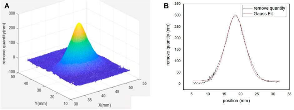
FIGURE 1. (A) Measured ion beam removal function. (B) One-dimensional profile of the removal function and its Gaussian fit.
The Fizeau interferometer (model is DynaFiz™) from Zygo company was used to measure the low spatial frequency surface figure of the mirrors. During the test, the surface normals of the reference mirror remain parallel to those of the mirror under test. A camera resolution of 1,200 × 1,200 pixels with a pixel size of 0.2635 × 0.2635 mm2 was employed. An optical profiler (model is ContourGT-X3) and atom force microscope (AFM, model is Icon Dimension) from Bruker company were used to measure the middle- and high-frequency surface morphologies. The optical profilometer used ×10 and ×50 magnification with test areas of 0.62 × 0.47 mm2 and 0.13 × 0.1 mm2, with minimum resolutions of 923 mm−1 and 103 mm−1, respectively. AFM used a 2 × 2 μm2 test area and 256 × 256 pixels resolutions.
Results and Discussion
Ion Beam Figuring of VFM
The surface figures of VFM before and after IBF are shown in Figure 2. The 2-mm edge area was removed from all sides of the mirror. The mirror was mechanically polished previously to a figure of 32.7 nm (RMS) with an ultrasmooth surface (roughness <0.3 nm). A small curvature existed in the surface profile which has a best-fit radius of 56.4 km (Figure 2A). If the best-fit sphere was subtracted, the residual figure error before IBF is 13.2 nm (RMS) (Figure 2B). The mirror surface profile (including the 2nd order spherical error) was figured by two iterations. After that, the radius of the best-fit sphere was increased to 603 km with a figure of 2.7 nm RMS (Figure 2C). Due to the small mirror thickness, it is difficult to completely remove the 2nd order curvature, and this extremely large radius of curvature will have negligible effect for application in the beamline. The residual height error after subtraction of the best-fit sphere was only 1.2 nm (RMS) (Figure 2D).
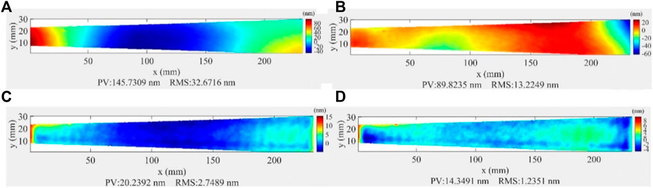
FIGURE 2. (A) Initial surface figure of VFM. (B) Initial surface figure after subtracting the best-fit sphere. (C) Surface figure after IBF. (D) Surface figure after IBF with the best-fit sphere subtracted.
The one-dimensional height profile along the length direction at the center area of the mirror is shown in Figure 3A. The height error (including the 2nd order curvature) decreased dramatically from 132.9 to 7.8 nm (PV) and from 33.9 to 2.2 nm (RMS). The height error after IBF with the best-fit sphere subtracted is also shown in Figure 3B. The residual error is 4.8 nm (PV) and 0.88 nm (RMS) after subtracting the best-fit sphere, while some small oscillations can still be seen in the height profile. These middle-frequency errors will need to be removed in future work.
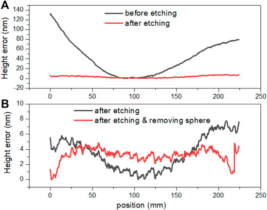
FIGURE 3. (A) One-dimensional height profile along the length direction of VFM before and after IBF. (B) Height error after IBF without and with the best-fit sphere was subtracted.
In order to further characterize the slope error of the figured surface topography, two-dimensional images of slope errors were made (as shown in Figure 4). The slope error was calculated along the length direction over the two-dimensional surface area, and the second-order curvature has been removed. Two different slope error maps with a spatial interval of 1 and 10 mm were calculated, and the RMS values were determined, respectively. In the case of a 1 mm interval (close to middle-frequency region), the slope error decreased from 0.77 to 0.28 μrad after two times figuring. In the case of the 10 mm interval, the slope error was smaller than in the 1 mm case in general, and it decreased from 0.65 to 0.08 μrad. A more detailed calculation of the slope error at different intervals (from 0.2635 to 42.16 mm) is shown in Figure 5.
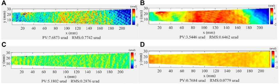
FIGURE 4. (A) Initial slope error calculated with 1 mm interval. (B) Initial slope error calculated with 10 mm interval. (C) Slope error after IBF calculated with 1 mm interval. (D) Slope error after IBF calculated with 10 mm interval.
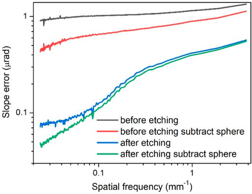
FIGURE 5. RMS values of two-dimensional slope errors of VFM calculated at different spatial frequencies.
In Figure 5, the slope error of the vertical axis is the root mean square of the slope error of the two-dimensional slope error maps, i.e., the root mean square value of slope error at different spatial frequencies. We calculated the slope error from pixel interval 1 to interval 160 (the interval is 1, and there are 160 groups of data points) and made the slope error-frequency graph. The spatial frequency of the horizontal axis is calculated from the selected interval (spatial frequency = 1/interval, pixel intervals range from 1 to 160, so the spatial frequencies range from 3.8 mm−1 to 0.0237 mm−1). It is worth noting that in the two-dimensional image, in order to better compare the two images, we cut off the image to make them the same size, but this is not carried out in the spatial frequency error distribution, so there is a slight vertical difference between the two images.
It can be seen that the slope error gradually decreased as the spatial intervals increased. The reduction of slope error is significantly larger at the lower frequency region, indicating a stronger correction effect of IBF in this region. As a result, the slope error calculated with larger intervals exhibited a much smaller value. Considering the different effects of the slope errors located in different frequencies on the X-ray wavefront [18], it is worth estimating the surface slope quality in a frequency-dependent way rather than using a fixed spatial interval.
Ion Beam Figuring of HFM
The surface figures of HFM before and after IBF are shown in Figure 6. A few millimeters of the edge area were removed from all sides of the mirror. A relatively large second-order curvature was observed in the mirror before IBF. After a single iteration figuring, the radius of curvature of HFM was increased from 26.7 to 267 km. The height error was reduced from 65.4 to 7.2 nm (RMS) (Figures 6A, C). If the best-fit sphere was subtracted, the residual figure error before IBF was 13.2 nm (RMS) (Figure 6B), and the residual error after IBF was only 1.1 nm (RMS) (Figure 6D).
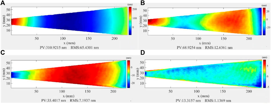
FIGURE 6. (A) Initial surface figure of HFM. (B) Initial surface figure after subtracting the best-fit sphere. (C) Surface figure after IBF. (D) Surface figure after IBF with the best-fit sphere subtracted.
The one-dimensional height profile along the length direction of the center area of the mirror is shown in Figure 7. The height error (including the 2nd order curvature) decreased dramatically from 290.5 to 31.5 nm (PV) and from 74.1 to 8.0 nm (RMS). The height error with subtracting the best-fit sphere after IBF is further shown in the following diagram of Figure 7. The residual error is 3.9 nm (PV) and 1.1 nm (RMS) after subtracting the best-fit sphere, while some small oscillations can still be seen in the height profile. These middle-frequency errors will need to be removed in future work.
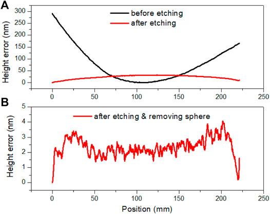
FIGURE 7. (A) One-dimensional height profile along the length direction of HFM before and after IBF. (B) Height error after IBF with the best-fit sphere was subtracted.
Figure 8 shows the two-dimensional slope error distribution of HFM. After figuring, the RMS of slope errors decreases from 0.78 to 0.29 μrad in the case of a 1-mm interval and from 0.64 to 0.08 μrad in the case of a 10-mm interval. Both VFM and HFM showed sub-hundred nanoradians slope error after IBF if a 10 mm spatial interval was used for estimation. Figure 9 shows the slope error of HFM at different frequencies. It can be seen that the evolution of slope error is similar to VFM, while the effectiveness of IBF correction in the lower frequency region is much better.
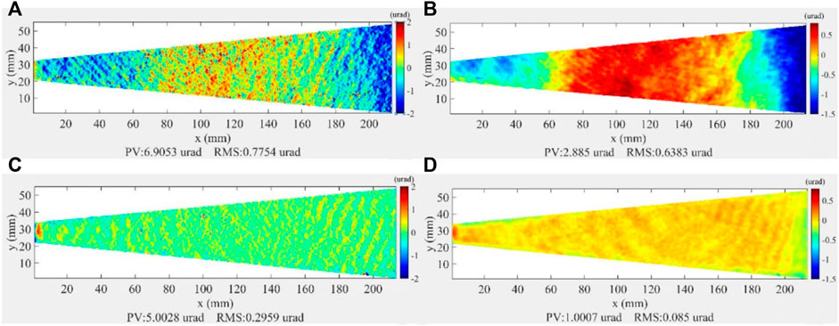
FIGURE 8. (A) Initial slope error calculated with 1 mm interval. (B) Initial slope error calculated with 10 mm interval. (C) Slope error after IBF calculated with 1 mm interval. (D) Slope error after IBF calculated with 10 mm interval.
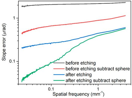
FIGURE 9. RMS values of two-dimensional slope errors of HFM calculated at different spatial frequencies.
To further estimate the absolute accuracy of our interferometer measurements, the HFM mirror was also measured by NOM in the optics group in SSRF. The trapezoidal mirror was mounted sideways in NOM, and a line profile indicated in Figure 10A was measured accordingly. The comparison of NOM and the interferometer results are shown in Figures 10B, C. The general trend of the height profiles of NOM and interferometer is similar while a difference of ±4 nm (PV) was observed. This can be caused by the reference error of the interferometer that was not perfectly corrected. The slope error measured by NOM is 160 nrad, given the relatively large beam size of NOM. The consistent results proved the high figure accuracy of the trapezoidal plane mirrors fabricated by IBF.
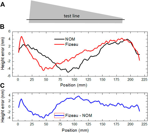
FIGURE 10. (A) Schematic representation of the line position of HFM measured by NOM. (B) Comparison of the line profiles measured by NOM and Fizeau interferometer after IBF. (C) Difference between the height profiles of two measurements.
Analysis of Surface Morphology in the Full Spatial Frequency Range
In addition, the low-frequency surface figure was measured by using the Fizeau interferometer; the middle and high spatial frequency morphologies of the mirrors were also measured before and after IBF by using an optical profiler and atom force microscope, respectively. The RMS values of VFM are listed in Table 1. The middle- and high-frequency roughness values after IBF are 0.23–0.25 and 0.11 nm (RMS), respectively, which are similar to before IBF.
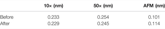
TABLE 1. Surface roughness measured by using an optical profiler and AFM before and after IBF.
The one-dimensional power spectral densities (PSDs) of the measured surface morphology of the interferometer, optical profiler, and AFM are calculated and shown together in Figure 11. It can be seen that in the low-frequency region of f < 1 mm−1, the surface height errors were significantly reduced, whereas the height error convergence become slower as the frequency increased. In the higher frequency region of f > 1–2 mm−1, the height errors remain almost the same as before, which indicates that the ion beam figuring process in this work has a negligible effect on the middle- and high-frequency errors.
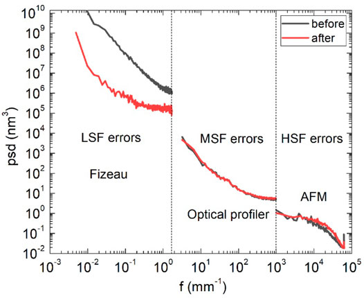
FIGURE 11. PSD results of VFM before and after IBF as measured by the Fizeau interferometer, optical profiler, and AFM.
Application in Hard X-Ray Micro-focusing Beamline in SSRF
After the high-precision ion beam figuring, a linear magnetron sputtering machine was used to coat both mirrors with 50-nm Rh film [19]. A thin Cr bonding layer was first deposited before the Rh layer. The coated mirrors were installed and applied in the bendable KB system in the end station of the hard X-ray micro-focusing beamline (XMF) in SSRF (Figure 12). The plane mirrors were bent into an elliptical shape by mechanical benders. The object distance of VFM is close to infinite, and the image distance is 42 cm; the object distance of HFM is 500 cm, and the image distance is 27 cm. Due to the toroidal mirror upstream providing collimation and pre-focusing in vertical and horizontal directions, respectively, the divergence angle of the incident beam is approximately 1 3 and 60 μrad for VFM and HFM. X-ray energy of 10 keV was used, and the grazing incidence is 3 mrad for both mirrors. The focal spot was measured by knife-edge scan to analyze the spot size and shape.
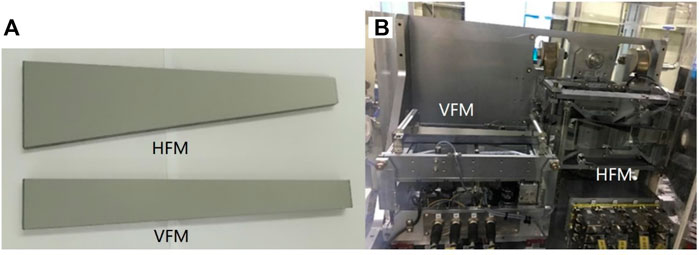
FIGURE 12. (A) Pictures of two trapezoidal mirrors after coating and (B) after the installation in the bendable KB system.
The focusing results are shown in Figure 13, and the simulation results performed by SHADOW software based on geometrical ray tracing were also added. The measured focal spot sizes (FWHM) are 2.8 and 2.4 μm in vertical and horizontal directions, respectively. The spot size in the horizontal direction is very close to the simulated result, while the one in the vertical direction is larger than the simulation. This can be caused by the surface errors of the upstream mirrors after long-term usage and the small error of the bender system in the vertical direction. The small figure error of the two mirrors has a negligible effect on the focusing result, according to simulation.
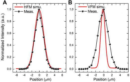
FIGURE 13. (A) Measured focusing spot of the KB system in a horizontal direction and (B) in a vertical direction.
Conclusion
High-precision X-ray plane mirrors were fabricated by the developed IBF process. The figure errors of the 240 mm length mirrors were reduced down to 1.1–1.2 nm (RMS), and the ultrasmooth middle- and high-frequency morphologies were maintained the same as before IBF. The two-dimensional slope errors at different spatial frequency ranges were studied in detail. It was found that IBF has a much better correction effect on slope errors with a lower frequency, and a sub-hundred nanoradian slope error was obtained if a spatial period of 10 mm was used in estimation instead of the conventional 1 mm. The two mirrors were successfully installed in the hard X-ray micro-focusing beamline in SSRF, and a focusing spot of 2.4 μm × 2.8 μm was obtained. The KB focusing system has been opened to user applications.
Currently, the middle-frequency height errors still exist in the figured mirror surface. It needs to be further corrected by IBF, and even smaller slope errors can be expected. The IBF technology will also be developed for figuring curved mirrors and other more complex surface profiles to meet the different requirements in the beamlines.
Data Availability Statement
The raw data supporting the conclusions of this article will be made available by the authors, without undue reservation.
Author Contributions
YZ performed the IBF experiments, characterization, and contributed to writing of the manuscript, QH supervised the work and finalized the manuscript, SY performed mirror installation and focusing experiments, JY assisted the IBF experiments, HH assisted the IBF experiments, YH performed the NOM measurement, HL contributed to characterizations, ZL supported the IBF platform, ZZ contributed to fabrication and analysis, and ZW co-supervised the work.
Funding
This work is supported by the National Natural Science Foundation of China (12075170, U2032169, and 12027810) and the Shanghai Rising-Star Program (No. 19QA1409200).
Conflict of Interest
The authors declare that the research was conducted in the absence of any commercial or financial relationships that could be construed as a potential conflict of interest.
Publisher’s Note
All claims expressed in this article are solely those of the authors and do not necessarily represent those of their affiliated organizations, or those of the publisher, the editors, and the reviewers. Any product that may be evaluated in this article, or claim that may be made by its manufacturer, is not guaranteed or endorsed by the publisher.
References
1. Eriksson M, van der Veen JF, Quitmann C. Diffraction-limited Storage Rings - a Window to the Science of Tomorrow. J. Synchrotron Radiat. (2015) 21(5):837–42. doi:10.1107/S1600577514019286
2. Yamauchi K, Mimura H, Kimura T, Yumoto H, Handa S, Matsuyama S, et al. Single-nanometer Focusing of Hard X-Rays by Kirkpatrick-Baez Mirrors. J. Phys Condens. Matter (2011) 23(39):394206. doi:10.1088/0953-8984/23/39/394206
3. Takei Y, Mimura H. Effect of Focusing Flow on Stationary Spot Machining Properties in Elastic Emission Machining. Nanoscale Res. Lett. (2013) 8(1):237. doi:10.1186/1556-276x-8-237
4. Hirata T, Takei Y, Mimura H. Machining Property in Smoothing of Steeply Curved Surfaces by Elastic Emission Machining. Procedia CIRP (2014) 13:198–202. doi:10.1016/j.procir.2014.04.034
5. Demmler M, Zeuner M, Allenstein F, Dunger T, Nestler M, Kiontke S. Ion Beam Figuring (IBF) for High Precision Optics. Proc. SPIE (2010) 7591:75910Y. doi:10.1117/12.840908
6. Yun L, Xing T, Xu J, Xu F, Lei N. Dwell Time Algorithm for the 3-axis Ion Beam Figuring System. Infrared Laser Eng (2012) 41(5):1300.
7. Chernyshev A, Chkhalo N, Malyshev I, Mikhailenko M, Toropov M. Matrix Based Algorithm for Ion-Beam Figuring of Optical Elements. Precis. Eng. (2021) 69(16). doi:10.1016/j.precisioneng.2021.01.006
8. Thiess H, Lasser H, Siewer F. Fabrication of X-Ray Mirrors for Synchrotron Applications. Nucl. Instrum. Methods Phys. Res. A (2010) 616(2-3):157–61. doi:10.1016/j.nima.2009.10.077
9. Shi Y, Huang Q, Qi R, Shen Z, Zhang Z, Wang Z. Theoretical and Experimental Study of Particle Distribution from Magnetron Sputtering with Masks for Accurate Thickness Profile Control. Coatings (2020) 10:357. doi:10.3390/coatings10040357
10. Peverini L, Guadalupi H, Michel T. Reflective Optics for EUV/x-ray Sources at Thales SESO: Possibilities and Perspectives. Proc. SPIE (2020) 11492:114920H. doi:10.1117/12.2570604
11. Liu C, Qian J, Assoufid L. Profile Etching for Prefiguring X-Ray Mirrors. J. Synchrotron Radiat. (2015) 22(2):458–60. doi:10.1107/s1600577515000624
12. Hand M, Alcock SG, Hillman M. Ion Beam Figuring and Optical Metrology System for Synchrotron X-Ray Mirrors. Proc. SPIE (2019) 11109:111090A. doi:10.1117/12.2528463
13. Wang T, Huang L, Vescovi M, Kuhne D, Tayabaly K, Bouet N, et al. Study on an Effective One-Dimensional Ion-Beam Figuring Method. Opt. Express (2019) 27(11):15368–81. doi:10.1364/oe.27.015368
14. Wang T, Huang L, Choi H, Vescovi M, Kuhne D, Zhu Y, et al. RISE: Robust Iterative Surface Extension for Sub-nanometer X-Ray Mirror Fabrication. Opt. Express (2021) 29(10):15114–32. doi:10.1364/oe.419490
15. Wang T, Huang L, Vescovi M, Kuhne D, Zhu Y, Negi VS, et al. Universal Dwell Time Optimization for Deterministic Optics Fabrication. Opt. express (2021) 29(23):38737–57. doi:10.1364/oe.443346
16.Shanghai-XFEL Beamline Project. Shanghai-XFEL Beamline Project (SBP) and Shanghai Soft X-Ray Free Electron Laser Facility (SXEFL) Reach Another Milestone: First Light and First Data (2021). Available at: https://www.shanghaitech.edu.cn/eng/2021/0626/c1260a66742/page.htm.
17. Jiang X, Wang J, Qing Q. The Chinese High-Energy Photon Source and its R&D Project. Synchrotron Radiat. News (2014) 27(6):27–31.
18. Pardini T, Cocco D, Hau-Riege SP. Effect of Slope Errors on the Performance of Mirrors for X-Ray Free Electron Laser Applications. Opt. Express (2015) 23(25):31889. doi:10.1364/oe.23.031889
Keywords: ion beam figuring, X-Ray mirror, height error, slope error, focusing
Citation: Zhang Y, Huang Q, Yan S, Yu J, Huang H, He Y, Luo H, Liu Z, Zhang Z and Wang Z (2022) High-Precision Ion Beam Figuring of X-Ray Plane Mirrors for the Bendable KB Focusing System. Front. Phys. 10:865411. doi: 10.3389/fphy.2022.865411
Received: 29 January 2022; Accepted: 19 April 2022;
Published: 24 May 2022.
Edited by:
Emmanouil P. Benis, University of Ioannina, GreeceReviewed by:
Giulia Festa, Museo Storico della Fisica e Centro Studi e Ricerche Enrico Fermi, ItalySimon Alcock, Diamond Light Source, United Kingdom
Copyright © 2022 Zhang, Huang, Yan, Yu, Huang, He, Luo, Liu, Zhang and Wang. This is an open-access article distributed under the terms of the Creative Commons Attribution License (CC BY). The use, distribution or reproduction in other forums is permitted, provided the original author(s) and the copyright owner(s) are credited and that the original publication in this journal is cited, in accordance with accepted academic practice. No use, distribution or reproduction is permitted which does not comply with these terms.
*Correspondence: Qiushi Huang, aHVhbmdxc0B0b25namkuZWR1LmNu; Shuai Yan, eWFuc2h1YWlAempsYWIub3JnLmNu