- 1Key Lab of Industrial Fluid Energy Conservation and Pollution Control, Qingdao University of Technology, Qingdao, China
- 2Changchun Institute of Optics, Fine Mechanics and Physics, Chinese Academy of Sciences (CAS), Changchun, China
In order to obtain a focusing flattop beam with high uniformity, complex modulation is used to modulate the optical pupil function, and the beam shaping algorithm is designed with a single phase-only spatial light modulator (SLM). Actually, the wavefront aberrations introduced by each element reduce the uniformity of the shaped beam. In particular, the wavefront aberrations in different positions have different effects on this complex modulation algorithm. However, there is a lack of the corresponding error data and robustness analysis. Here, the error and robustness of the complex modulation algorithm are analyzed when different types of aberrations (defocus, astigmatism, and coma) exist in different positions of the shaping optical system, and the mixed area magnification-free (MRAF) algorithm is used as a reference for comparison. The results show that coma has the greatest effect on the beam shaping quality. It is also proved that the impact on the beam quality when there are aberrations in the laser and beam expansion system is greater than those in the SLM and the focusing lens for the complex modulation algorithm, which is different from the MRAF case.
Introduction
The beam shaping can generate a flattop focusing beam, which can significantly improve the quality of precise test or laser processing [1–3]. The phase-only spatial light modulator (SLM) which is convenient for rapid shape conversion, uses a liquid crystal device to modulate the beam and has been successfully applied in the beam shaping [4, 5]. Based on the relationship between the pupil function and the light intensity distribution in the focus plane [6–8], SLM is used to modulate the parallel beam, and a flattop focusing beam with arbitrary shapes can be generated when the modulated parallel beam passes through a focusing lens. The typical algorithm is the GS algorithm [9], which modulates the optical pupil phase, but the uniformity of the focusing beam is hard to meet the requirements of higher precision processing. Then, the MRAF (mixed region amplification freedom) algorithm was further proposed based on the GS algorithm [10]. It improves the uniformity and has been applied in the research of two-photon polymerization [11]. However, the beam quality is still difficult to control, and the initial phase needs to be strictly estimated.
The complex modulation algorithm which can modulate the amplitude and phase synchronously appears [12–14]. This method has been successfully applied to the shaping of parallel beams, showing good performance potential. Here, the grating complex modulation technology is combined with the phase retrieval theory to modulate the optical pupil function and generate a focusing beam with high uniformity [15]. But, the actual uniformity of the shaped facula is different from the ideal result. In particular, the wavefront aberrations of the illumination system and focusing objective lens have different effects on the shaping quality of the complex modulation algorithm [16]. However, the error theoretical analysis of this beam shaping algorithm using phase-only SLM has not been reported. In this article, the influence of different positions and different types of wavefront aberrations on the complex modulation beam shaping will be studied, and the MRAF algorithm is selected as a reference for comparison.
Guidelines for Manuscript Preparation
In Fourier optics, the relationship between the focus plane and the pupil function is expressed as a simple Fourier transform [7–9]:
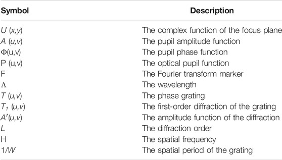
where U (x,y) is the complex function of the focus plane, x,y is the Cartesian coordinate system of the focus plane, A (u,v) is the pupil amplitude function, Φ(u,v) is the pupil phase function, P (u,v) is the optical pupil function, u,v is the normalized coordinates in the pupil plane, f is the defocus parameter, and F is the Fourier transform marker, as shown in Table 1. Beam shaping methods can modulate the phase part Φ(u,v) of the optical pupil function P (u,v), such as the GS and MRAF algorithms. In contrast, the phase part Φ(u,v) and the amplitude part A (u,v) of the optical pupil function P (u,v) = A (u,v)exp [iΦ(u,v)] are modulated in the complex modulation algorithm.
According to Formula (1), the complex function U (x,y) of the focus plane to be shaped is inversely calculated, and the complex function P (u,v) of the exit pupil is obtained. After obtaining the complex pupil function, the next step is to modulate the complex optical pupil function A′(u,v)exp [iΦ(u,v)] into a phase grating. The principle is as follows [14–18]:
where l is the diffraction order, η is the spatial frequency, and 1/W is the spatial period of the grating. Each diffraction order of the grating contains the information of amplitude A′(u,v) and phase Φ(u,v). It is worth noting that in Formula (2), when l = 1, the first-order diffraction from the phase grating T (u,v) contains exp [iΦ(u,v)] and has the maximum power. It can be seen that the positive first-order diffraction has the effective information:
Then, the amplitude distribution of the first-order diffraction is:
In this way, when the amplitude distribution function A (u,v) and Formula (4) are inversely calculated to obtain the amplitude A′(u,v) and substituted into Formula (2), the first-order diffraction of the SLM grating will contain amplitude and phase modulation information. By using an objective lens to focus the first-order diffraction beam, the required modulated facula can be obtained at the focal plane.
The schematic setup for beam shaping is shown in Figure 1. The laser output by fiber coupling passes through the beam expander and is directly irradiated on the SLM through a mirror to generate a modulated beam. After converging by the objective lens, the shaped faculae can be obtained in the focus plane. A polarizer and a half-wave plate are added in the optical path to adjust the polarization direction of the light beam to be consistent with the modulation polarization direction of the liquid crystal element in the SLM to obtain the maximum modulation efficiency. The basic parameters of the optical system are as follows: the laser wavelength is 980nm, the diameter of the laser tail fiber is 9μm, the focal length of the coupling lens is 15.5mm, the focal lengths of the two lenses of the beam expander group are 35 and 150 mm, the beam intensity at the edge is 42% of the center, and the focal length of the focusing objective lens is 75 mm. The pixel size of the camera is 4.8 macrons. The simulation and experimental results of the complex modulation algorithm for the square flattop focusing beam are shown in Figure 2. Figure 2A shows the phase mask of the complex modulation algorithm, Figure 2B shows the simulated ideal result of a square focal facula, and Figure 2C shows the experimental result of a square focal facula. It can be concluded that the focal facula of the complex modulation algorithm has good uniformity in theory, but there is a deviation between the actual experimental data and the ideal results.

FIGURE 2. Ideal and experimental results of square flattop focusing beam shaping with complex modulation algorithm. (A) Phase mask, (B) ideal result of focal facula, and (C) the experimental result of focal facula.
Error and Robustness Analysis
In order to evaluate the robustness of the algorithm, Zernike polynomials are multiplied by coefficients to represent different types of wavefront aberrations. The MRAF algorithm is used as a reference to study the influence of various aberrations on beam shaping uniformity. In particular, because the complex modulation algorithm uses a phase grating to generate amplitude and phase modulation, the wavefront aberrations at different positions have different effects on the quality of the shaped and focused beam, which can be divided into two cases: ➀ aberrations exist in the laser source and the beam expander; and ➁ aberrations exist in the SLM and the objective lens. The simulation analysis is implemented as following, while the numerical aperture diameter of the image plane is 0.0533, and the pixel size of the camera is 4.8 macrons.
Aberrations in the Laser Source and the Beam Expander
When there is an aberration in the laser source and the beam expander, Formula (2) becomes:
where Δ is the wavefront aberration. The Zernike polynomials are applied to represent the different types of aberrations, namely defocus (Z20), coma (Z22), and astigmatism (Z31). Because the numerical aperture of the laser processing system is less than 0.1, the wavefront aberration is small, and the coefficients of Zernike polynomials are set to be 0.6 π rad.
It is also necessary to strictly evaluate the uniformity of the shaped beam. The mean square value (RMS) of beam roughness is defined as:
where Std ( ) is the standard deviation function, and Mean ( ) is the average function, and the Max of beam roughness is defined as:
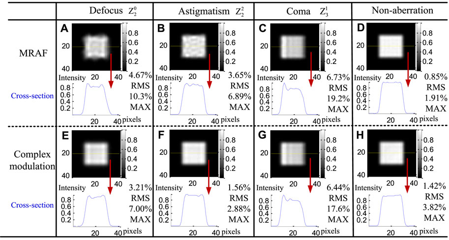
A beam shaping simulation test for evaluating the fading caused by different types of aberrations is carried out using the same parameters as Figure 2, and the results by comparing with the MRAF are shown in Figure 3. The uniformity of the facula is evaluated by cross section and marked with the yellow dotted line in the figure. Here, the ROI (region of interest) is selected from the 11th ∼ 25th pixels for the uniformity calculation.
For the non-aberration case, the MRAF algorithm can obtain a better uniform facula than the complex modulation algorithm. The roughness of the facula in Figure 3D is less than that in Figure 3H and can reach 1.91% (max). For the complex modulation, the 0
From the aforementioned results, it can be concluded that the robustness of the complex modulation algorithm is better than that of the MRAF algorithm when the aberrations locate in the laser and beam expander system.
Aberrations in the SLM and the Objective Lens
When the SLM and the objective lens have aberrations, Formula (2) becomes:
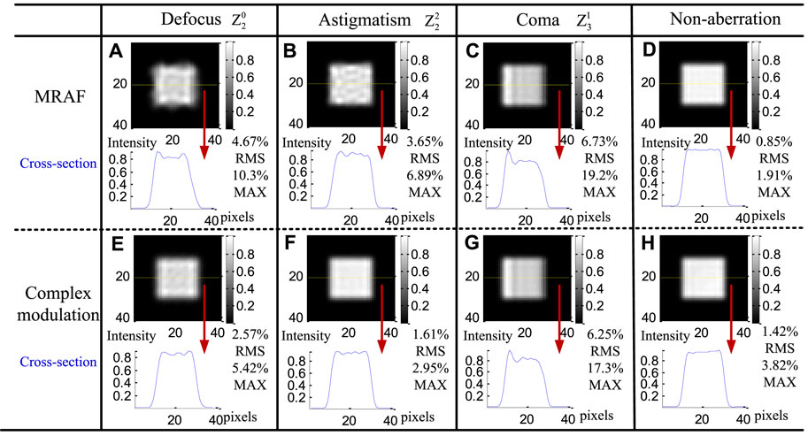
This is a different case from Formula (5). Here, the coefficients of Zernike polynomials representing different types of wavefront aberrations are still 0.6 π rad. The faculae results of the MRAF algorithm and complex modulation algorithm are shown in Figure 4. The 0
The sphere aberration is also analyzed and has a similar result to that of the defocus aberration. Here, the detailed description of the sphere aberration case is omitted. Comparing Figure 3E with Figure 4E, the effect of defocus aberration existing in the objective lens and the SLM on the beam quality is smaller than that existing in the laser source and the beam expander. Therefore, the optical shaping quality of the complex amplitude algorithm is more easily affected by the illumination part of the optical system, which is also consistent with Ref. [18]. According to the aforementioned results, the robustness of the complex modulation algorithm is still better than that of the MRAF algorithm when the aberrations exist in the SLM and the objective lens.
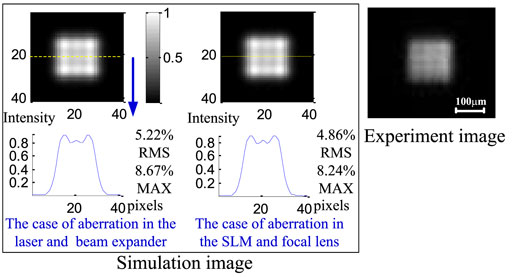
Another analysis has been carried out for the case of the defocus aberration amount increasing to π, as shown in Figure 5 [16]. Although the shapes of the facula patterns (the grids) are different from those of Figure 3E and Figure 4E, as the aberration increases, the patterns are still similar in these two cases. In order to verify the simulation, the experiment is carried out, and the grids also appear in the shaped pattern, which is similar to the simulation. So, it can be concluded that the main difference focuses on the error amount.
Conclusion
In order to meet the requirement of high uniformity of the focusing beam, the complex modulation on the pupil function with a phase-only SLM is introduced. But under the actual working condition, the wavefront aberrations will reduce the quality of the beam shaping due to various errors of the components. In particular, the various aberrations will generate the different facula patterns which are suitable for the fast fault diagnosis. It is found that astigmatism has the least influence on the quality of the shaped beam, and coma has the greatest influence. Therefore, attention should be paid to centering installation in the system alignment. In addition, for the complex modulation algorithm, in which there is an aberration between the laser and the beam expander system, the impact on the quality of the shaped beam is greater than that when there is an aberration between the SLM and the objective lens, and that is different from the MRAF case.
Data Availability Statement
The original contributions presented in the study are included in the article/Supplementary Material, further inquiries can be directed to the corresponding author.
Author Contributions
JS: writing. HD: simulation and writing. SH: writing. SS: supervision. ZN:writing and analysis. JS, HD, SN, and ZN are the co-first authors.
Funding
This work was supported by the China Postdoctoral Science Foundation (Grant No. 2018M632639), Key Technology Research and Development Program of Shandong (Grant Nos. 2019GGX104106 and 2019JZZY010402), Higher Education Discipline Innovation Project-the 111 plan (Grant No. D21017), and National Natural Science Foundation of China (Grant Nos. 51775289, 51605239).
Conflict of Interest
The authors declare that the research was conducted in the absence of any commercial or financial relationships that could be construed as a potential conflict of interest.
Publisher’s Note
All claims expressed in this article are solely those of the authors and do not necessarily represent those of their affiliated organizations, or those of the publisher, the editors, and the reviewers. Any product that may be evaluated in this article, or claim that may be made by its manufacturer, is not guaranteed or endorsed by the publisher.
References
1. Pang H, Cao A, Liu W, Deng Q. Alternative Design of Dammann Grating for Beam Splitting with Adjustable Zero-Order Light Intensity. IEEE Photon J (2019) 11(2):1500909. doi:10.1109/jphot.2019.2899903
2. Liu D, Wang Y, Zhai Z, Fang Z, Tao Q, Perrie W, et al. Dynamic Laser Beam Shaping for Material Processing Using Hybrid Holograms. Opt Laser Techn (2018) 102:68–73. doi:10.1016/j.optlastec.2017.12.022
3. Shao J, Zhang R, Han S, Dong H, Sun S. The Activation Threshold Evaluation of Metallization for Aluminum Nitride Ceramic under Nanosecond Laser Pulses in Air. Ceramics Int (2021) 47:24707–12. doi:10.1016/j.ceramint.2021.05.193
4. Wang D, Zhang J, Wang H, Xia Y. Variable Shape or Variable Diameter Flattop Beam Tailored by Using an Adaptive Weight FFT-Based Iterative Algorithm and a Phase-Only Liquid crystal Spatial Light Modulator. Opt Commun (2012) 285(24):5044–50. doi:10.1016/j.optcom.2012.08.081
5. Hasegawa S, Hayasaki Y, Nishida N. Holographic Femtosecond Laser Processing with Multiplexed Phase Fresnel Lenses. Opt Lett (2006) 31(11):1705–7. doi:10.1364/ol.31.001705
6. Fienup JR, Marron JC, Schulz TJ, Seldin JH. Hubble Space Telescope Characterized by Using Phase-Retrieval Algorithms. Appl Opt (1993) 32(10):1747–67. doi:10.1364/ao.32.001747
7. Fienup JR. Phase Retrieval Algorithms: a Comparison. Appl Opt (1982) 21(15):2758–69. doi:10.1364/ao.21.002758
8. Shao J, Ma DM. Wavefront Measurement by Phase Retrieval through Single Defocus Intensity Patterns. Laser Phys (2013) 23(7):075003. doi:10.1088/1054-660x/23/7/075003
9. Pang H, Liu W, Cao A, Deng Q. Speckle-reduced Holographic Beam Shaping with Modified Gerchberg-Saxton Algorithm. Opt Commun (2019) 433:44–51. doi:10.1016/j.optcom.2018.09.076
10. Pasienski M, DeMarco B. A High-Accuracy Algorithm for Designing Arbitrary Holographic Atom Traps. Opt Express (2008) 16(3):2176–90. doi:10.1364/oe.16.002176
11. Zhang C, Hu Y, Du W, Wu P, Rao S, Cai Z, et al. Optimized Holographic Femtosecond Laser Patterning Method towards Rapid Integration of High-Quality Functional Devices in Microchannels. Sci Rep (2016) 6:33281. doi:10.1038/srep33281
12. Gualdrón O, Davis J, Nicolás J, Campos J, Yzuel MJ. Complex Encoding of Rotation-Invariant Filters onto a Single Phase-Only Spatial Light Modulator. Appl Opt (2003) 42(11):1973–80. doi:10.1364/AO.42.001973
13. Arrizón1 V, Ruiz1 U, Mendez1 G, Apolinar-Iribe A. Zero Order Synthetic Hologram with a Sinusoidal Phase Carrier for Generation of Multiple Beams. Opt Express (2009) 17(4):2663. doi:10.1364/OE.17.002663
14. Qi Y, Chang C, Xia J. Speckleless Holographic Display by Complex Modulation Based on Double-phase Method. Opt Express (2016) 24:30368–78. doi:10.1364/oe.24.030368
15. Shao J, Haase T, Zhang R, Aguergaray C, Broderick N, Sun S. Focusing Flattop Beam Shaping with Complex Modulation Holography. AIP Adv (2021) 11(10):105118. doi:10.1063/5.0065903
16. Shao J, Haase T, Aguergaray C, Broderick N, Sun S. Study on the Alignment Error of Complex Modulation for Focusing Flattop Beam Shaping. Opt Commun (2021) 498:127230. doi:10.1016/j.optcom.2021.127230
17. Davis JA, Cottrell DM, Campos J, Yzuel MJ, Moreno I. Encoding Amplitude Information onto Phase-Only Filters. Appl Opt (1999) 38(23):5004–13. doi:10.1364/ao.38.005004
Keywords: holography, gratings, diffractive optics, error analysis, focusing beam shaping
Citation: Shao J, Dong H, Han S, Sun S and Nie Z (2022) The Error Analysis of the Complex Modulation for Flattop Focusing Beam Shaping. Front. Phys. 10:863046. doi: 10.3389/fphy.2022.863046
Received: 26 January 2022; Accepted: 23 February 2022;
Published: 23 March 2022.
Edited by:
Hongwei Chu, Shandong University, ChinaCopyright © 2022 Shao, Dong, Han, Sun and Nie. This is an open-access article distributed under the terms of the Creative Commons Attribution License (CC BY). The use, distribution or reproduction in other forums is permitted, provided the original author(s) and the copyright owner(s) are credited and that the original publication in this journal is cited, in accordance with accepted academic practice. No use, distribution or reproduction is permitted which does not comply with these terms.
*Correspondence: Jing Shao, cXVueWluZzEyQDE2My5jb20=; Zhenwei Nie, bmllemhlbndlaUBob3RtYWlsLmNvbQ==
 Jing Shao
 Hao Dong1


