 Yan Wei Ji
 Xi Kui Ma1
 Hua Jie Hu
 Xin Zhong Li
- 1State Key Laboratory of Electrical Insulation and Power Equipment, School of Electrical Engineering, Xi’an Jiaotong University, Xi’an, SN, China
- 2School of Physics and Engineering, Henan University of Science and Technology, Luoyang, China
Optical analog computing and spatial differentiation have received great attention in many fields. In the field of biology and medicine, it is important to get the high contrast of phase images on a subwavelength scale. Compared with other methods, the optical methods based on the photonic spin Hall effect (PSHE) have the advantages of low costs and detailed detections, but this method also has the disadvantages of lower contrasts. Our work is aimed to improve the contrasts for the edges. In the study, we explore the spin Hall effect of light (SHEL) based on uniaxial crystals and investigate the effects of these crystals on spatial differentiation. It can be seen that in the elliptic–hyperbolic crystal, the PSHE can be enhanced significantly and the spatial differentiation contrasts are consistent with the enhancement of PSHE, which implies that this kind of medium would provide more possibilities in micro imaging.
Introduction
Nowadays, information technology has changed people’s daily life, and people create more and more calculation methods to improve the life quality. Optical analog computing is a widely used method to analyze the field distribution through an optical system, which has the advantages of real-time imaging, energy conservation, and simple principle [1–8]. Therefore, it is widely applied in spatial differentiation. Spatial differentiation is an important way to get information by extracting the edges from the figure, which can save the amount of information preservation and make the images clear for observation, especially in the biological and medical fields. For example, doctors can diagnose the physical condition of patients by observing the outline of red blood cells, and biologists can also use the method to explore the characteristics of plant cells [9].
There are many research studies on spatial differentiation at the subwavelength scale. Edge detections could be realized by optical systems [10, 11], such as metasurfaces [12], excited surface plasmon polaritons (SPPs) [13], or the optical bulky systems of Fourier lenses and filters [14, 15]. Methods based on SPPs or optical metasurfaces have the disadvantages of high price [16], and the preparations before the experiments are very complex [17]. In addition, the minimum width of slots that can be distinguished based on SPPs is 2.4
PSHE or the SHEL is a phenomenon that photons with opposite spins would drift in opposite directions perpendicular to the refractive index gradient [19–21]. The reason for the phenomenon is that when photons encounter media with the refractive index gradient during the process of transmission, the orbital angular momentum would interact with spin angular momentum, and then the photons with opposite spins would split. In other words, the reason for the PSHE is spin–orbit interaction (SOI). SOI has been investigated in the past decades [22–28]. The phenomena of SOI and PSHE often occur during the reflection and transmission process of light. Therefore, there are some researchers investigating the spatial differentiation based on PSHE at the air–prism interface [18, 29]. In this case, the mechanism of edge detections can be understood as deriving the complex amplitude of the incident light field. When a light beam passes through the phase object, the phase distributions for the passing light field are not equal to 0, while those of the blocked light field are 0. In this condition, there exist steps of phase distributions between the blocked light field and passing light field, and the discontinuity on phase generated the edges after the optical system.
To improve the contrasts of edges based on the PSHE method, we turn our attention to anisotropic material. In the past 20 years, the PSHE in a uniaxial crystal has been investigated with a positive index [30]. In addition, the SOI in certain uniaxial crystal [31] and so on [32–36] are also studied. There are three kinds of uniaxial crystals, and two of them are metamaterials with negative index. In this study, first we analyzed the PSHE in the simulation of the reflected field where a Gaussian beam is incident at the air–prism interface. By changing the index systems of uniaxial crystals, the enhancement order of PSHE among crystals with different dispersion relations is achieved more convincingly. Then, we used the optical system for spatial differentiation. In the same index system, the derivation results for different materials show that the edge contrasts
Theoretical analysis
The properties of the uniaxial crystal
The reflection schematic diagram of the Gaussian beam at the air–uniaxial crystal interface is shown in Figure 1. The optical axis of the uniaxial crystal lies in the
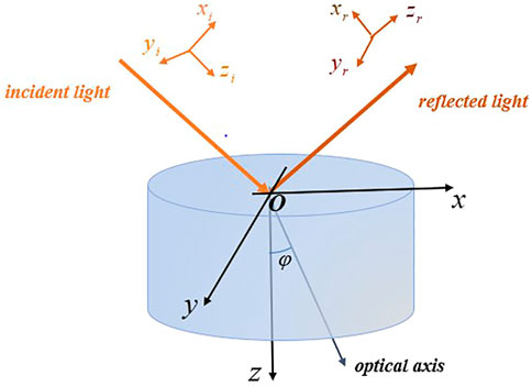
FIGURE 1. Schematic model of a uniaxial crystal sample.
In the study, the optical axis is set parallel to the z-axis for simplicity. According to the previous research about the beam propagating in uniaxial crystals [37–39], the constitutive relations in the anisotropic medium are given as:
In uniaxial crystals,
where
For elliptic–elliptic dispersion:
The relationships of wave vectors for p wave and s wave are different and written as follows:
The
The photonic spin Hall effect based on uniaxial crystal
As mentioned before, the spin components of the reflected beam split owing to the SOI. In this section, the PSHE based on uniaxial crystals with different dispersion relations is explored. The spin splitting phenomenon schematic of the Gaussian beam reflection process is shown in Figure 2. The local coordinate systems attached to the incident beam and the reflected beam can be expressed as
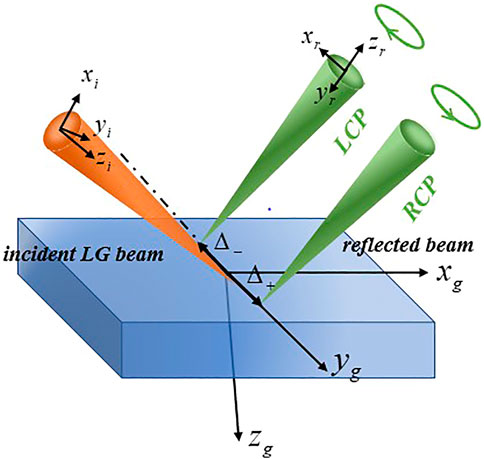
FIGURE 2. Spin splitting phenomenon schematic of Gaussian beam.
The Gaussian beam profiles can be expressed as
Here,
where
As we know, for an arbitrarily polarized beam, its polarization state can be constructed from a vector superposition of two orthogonal circular polarizations. Usually, the left circular polarization (LCP) is noted as
After the Fourier transform of
After some straightforward calculations, the shifts for RCP and LCP components for the reflected beam can be expressed as follows [40]:
Also, the W is written as
The spatial differentiation based on photonic spin Hall effect
There are many methods for spatial differentiation based on PSHE. It can be seen that the contrasts of the edges are relevant to the material characters of the reflecting surface. Also, the relevant optical setups [29] are shown in Figure 3.
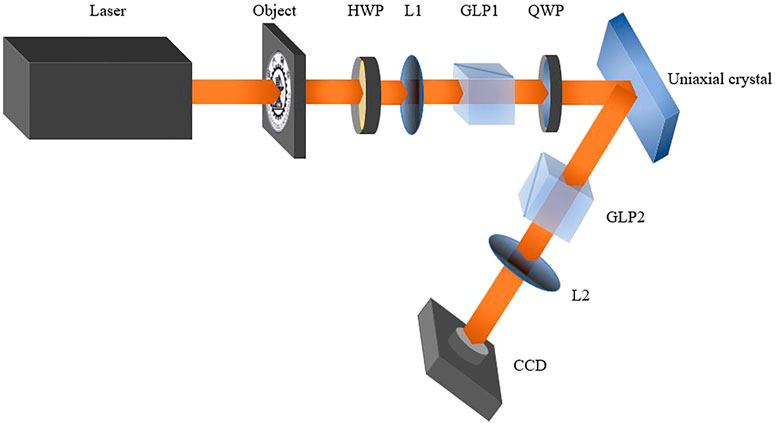
FIGURE 3. Optical setups for spatial differentiation based on PSHE.
The setup arrangement is used to detect the edges of the school badge. The half-wave plate (HWP) is used to adjust the intensity of the beam to prevent the CCD from being overexposed. The first lens (L1) is used to collimate the beam which is parallel. The first Glan laser polarizer (GLP1) and the second Glan laser polarizer (GLP2) are used to change the polarization states of the incident beam and the reflected beam. The second lens (L2) could convert the divergent beam to a parallel beam. Here, we introduce the derivation process for the spatial differentiation formula according to the relevant Ref. [29] and choose the Gaussian beam with a polarization electric field
Also, the Quarter Wave Plate (QWP) whose optics axis was set as
When the beam reflects at the surface of the uniaxial crystal, Eq. 19 is substituted into Eq. 12. Also, the angular spectrum of the reflected beam is written as
The
In Eq. 21 above, the
The inverse Fourier transform is performed on both sides of Eq. 22, and the result shows that
Thus, the setup arrangements in Figure 3 could achieve the two-dimensional edge detection of the object information.
Simulation results
When a Gaussian beam reflects at the surface of a uniaxial crystal, the photons with different spins would shift to the opposite directions as shown in Eq. 16. The beam split distance between two beams
In addition, setting the value of the index
Inserting the value of
The expressions of
Taking the index system of the quartz crystal, for example, the distributions of the
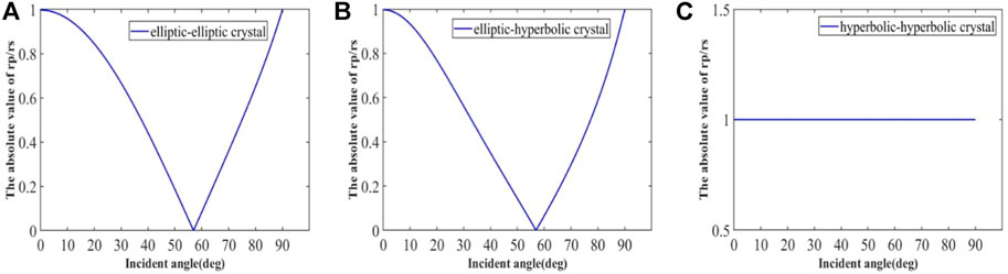
FIGURE 4. Curves of the value of
Comparing Figure 4A with Figure 4B, we can see that the change of
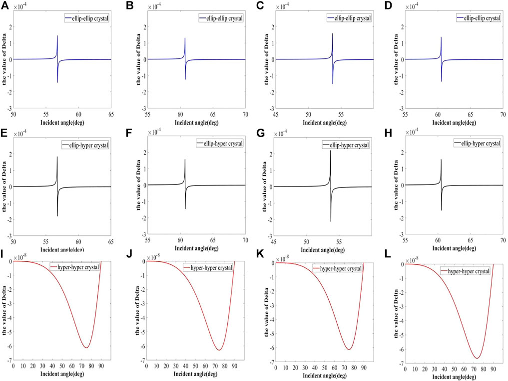
FIGURE 5. Distributions of spin splitting distance
The four rows correspond to the index system of quartz crystal (

FIGURE 6. Original picture of the school badge for edge detection.
The spatial differentiation effect based on different uniaxial crystals is shown in Figure 7. Figure 7 has eight subfigures, and the figures correspond to the materials of the first two columns in Figure 5. According to the index systems, these figures are divided into four groups: (a) and (b), (c) and (d), (e) and (f), and (g) and (h). The two figures in one group share the same index system and correspond to elliptic–elliptic crystal and elliptic–hyperbolic crystal, respectively. Take Figures 7A,B, for instance, it can be seen that Figure 7B has sharper edges than Figure 7A, while all the intensity values in Figures 7A,B are normalized values based on original intensity values. In these two original figures, we take the largest intensity value as
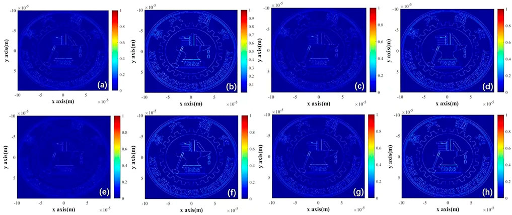
FIGURE 7. Spatial differentiation effect based on materials with different index systems.
It can be found that there is consistency between the maximum value of
The index
By introducing two indexes
where the
In addition, uniaxial crystals with a certain kind of dispersion relation have great advantages over the traditional prism. The indexes of the quartz crystal are applied in these simulations, and the edge detection effects based on different materials are shown in Figure 8. There are three subfigures in Figure 8, and the intensity values of these subfigures are processed values based on original intensity values. The processing method is similar to that in Figure 7. We take the largest value of the three original intensity distributions as
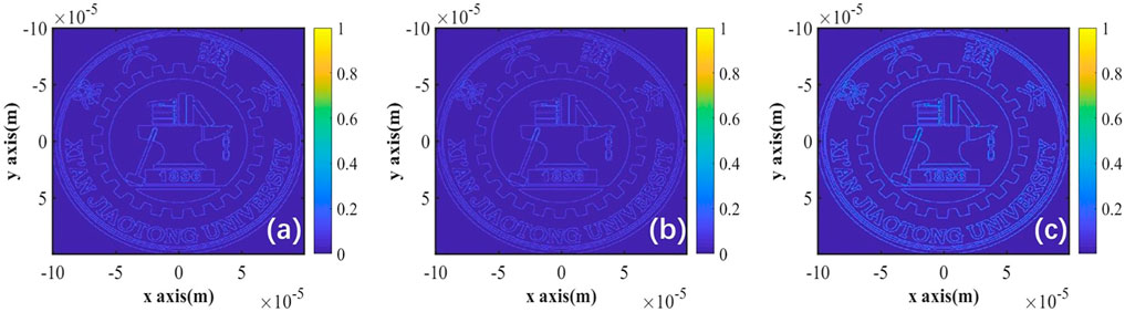
FIGURE 8. Edge detection effects based on different materials. (A): traditional prism. (B): elliptic–elliptic crystal. (C): elliptic–hyperbolic crystal.
The effect based on the glass prism in Figure 8A is similar to that in Figure 8B based on the elliptic–elliptic crystal. The edges in both figures are not clear enough. The effect based on the elliptic–hyperbolic crystal in Figure 8C has sharper edges and conveys more figure information than the two other effects. In order to make the comparison among the three figures more intuitive, the intensity distributions based on different materials along the certain region at the axis of
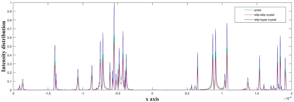
FIGURE 9. Light intensity distribution at
Conclusions and discussion
Our work is aimed to explore the optical characters of uniaxial crystals and compare the characters with those in the PSHE and edge detections. Setting the uniaxial crystals with different dispersion relations under the same parameter system, the numerical simulation results show the order of the PSHE enhancement as follows: elliptic–hyperbolic crystal
Elliptic–hyperbolic uniaxial crystal is a metamaterial with a negative index, which is a kind of artificial material with special characters compared with traditional materials. The advantages of elliptic–hyperbolic material mentioned before have brought a discovery that the application of metamaterials would open up new prospects in the field of edge detection.
The applications of metamaterials are still in the stage of testing and small batch production for their high costs. However, materials used for optical differentiation usually are reused, which means that the requirements for resistance of materials are high. In the long run, the methods based on metamaterials are relatively inexpensive and could be developed and widely used in the image processing field.
Data availability statement
The original contributions presented in the study are included in the article/Supplementary Material; further inquiries can be directed to the corresponding authors.
Author contributions
YJ proposed the idea. YJ wrote the original manuscript. YJ and HH performed the simulation work. XM helped in revising the original manuscript, and XL supervised the research work.
Funding
This work was supported by the Key Scientific Research Projects of Institutions of Higher Learning of Henan Province Education Department (No. 21zx002) and the National Natural Science Foundation of China (No. 11974102).
Conflict of interest
The authors declare that the research was conducted in the absence of any commercial or financial relationships that could be construed as a potential conflict of interest.
Publisher’s note
All claims expressed in this article are solely those of the authors and do not necessarily represent those of their affiliated organizations, or those of the publisher, the editors, and the reviewers. Any product that may be evaluated in this article, or claim that may be made by its manufacturer, is not guaranteed or endorsed by the publisher.
References
1. Pors A, Nielsen MG, Bozhevolnyi SI. Analog computing using reflective plasmonic metasurfaces. Nano Lett (2015) 15(1):791–7. doi:10.1021/nl5047297
2. Moeini MM, Sounas DL. Discrete space optical signal processing. Optica. (2020) 7(10):1325. doi:10.1364/OPTICA.400365
3. Kwon H, Sounas D, Cordaro A, Polman A, Alù A. Nonlocal metasurfaces for optical signal processing. Phys Rev Lett (2018) 121(17):173004. doi:10.1103/PhysRevLett.121.173004
4. Wesemann L, Panchenko E, Singh K, Della Gaspera E, Gómez DE, Davis TJ, et al. Selective near-perfect absorbing mirror as a spatial frequency filter for optical image processing. APL Photon (2019) 4(10):100801. doi:10.1063/1.5113650
5. Zangeneh-Nejad F, Fleury R. Topological analog signal processing. Nat Commun (2019) 10(1):2058. doi:10.1038/s41467-019-10086-3
6. Momeni A, Rajabalipanah H, Abdolali A, Achouri K. Generalized optical signal processing based on multioperator metasurfaces synthesized by susceptibility tensors. Phys Rev Appl (2019) 11(6):064042. doi:10.1103/PhysRevApplied.11.064042
7. Xu DY, He SS, Zhou JX, Chen SZ, Wen SC, Luo HL, et al. Goos–Hänchen effect enabled optical differential operation and image edge detection. Appl Phys Lett (2020) 116(21):211103. doi:10.1063/5.0006483
8. Wan L, Pan DP, Yang SF, Zhang W, Potapov AA, Wu X, et al. Optical analog computing of spatial differentiation and edge detection with dielectric metasurfaces. Opt Lett (2020) 45(7):2070. doi:10.1364/OL.386986
9. Huo PC, Zhang C, Zhu WQ, Liu MZ, Zhang S, Zhang S, et al. Photonic spin-multiplexing metasurface for switchable spiral phase contrast imaging. Nano Lett (2020) 20(4):2791–8. doi:10.1021/acs.nanolett.0c00471
10. Dobson KK, Jia W, Poon TC. Anisotropic edge enhancement in optical scanning holography with spiral phase filtering[J]. Chin Opt Lett (2016) 14(1):010006. doi:10.3788/COL201614.010006
11. Li ZH, Yu ZP, Hui H, Li HH, Zhong TT, Liu HL, et al. Edge enhancement through scattering media enabled by optical wavefront shaping. Photon Res (2020) 8(6):954. doi:10.1364/PRJ.388062
12. Luo HL, Ling XH, Zhou XX, Luo HL, et al. Hunan Provincial Key Laboratory of Intelligent Information Processing and Applications, College of Physics and Electronic Engineering, Hengyang Normal University, Hengyang 421002, ChinaSchool of Physics and Electronics, Hunan Normal University, Changsha 410081, China Spin-orbit interaction of a light beam under normal incidence at a sharp interface and its enhancement. Acta Phys Sin (2020) 69(3):034202. doi:10.7498/aps.69.20191218
13. Zhu TF, Zhou YH, Lou YJ, Ye H, Qiu M, Ruan ZC, et al. Plasmonic computing of spatial differentiation. Nat Commun (2017) 8(1):15391. doi:10.1038/ncomms15391
14. Goodman J. Introduction to fourier optics, second edition. Opt Eng (1996) 35(5):1513. doi:10.1117/1.6011212nd ed.
15. Qiu XD, Li FS, Zhang WH, Zhu ZH, Chen LX. Spiral phase contrast imaging in nonlinear optics: Seeing phase objects using invisible illumination. Optica. (2018) 5(2):208. doi:10.1364/OPTICA.5.000208
16. Kildishev AV, Boltasseva A, Shalaev VM. Planar photonics with metasurfaces. Science (2013) 339(6125):1232009. doi:10.1126/science.1232009
17. Genevet P, Capasso F, Aieta F, Khorasaninejad M, Devlin R. Recent advances in planar optics: From plasmonic to dielectric metasurfaces. Optica. (2017) 4(1):139. doi:10.1364/OPTICA.4.000139
18. Zhu TF, Lou YJ, Zhou YH, Zhang JH, Huang JY, Li Y, et al. Generalized spatial differentiation from the spin Hall effect of light and its application in image processing of edge detection. Phys Rev Appl (2019) 11(3):034043. doi:10.1103/PhysRevApplied.11.034043
19. Long WJ, Pan JT, Guo XY, Liu XH, Lin HL, Zheng HD, et al. Optimized weak measurement of orbital angular momentum-induced beam shifts in optical reflection. Photon Res (2019) 7(11):1273. doi:10.1364/PRJ.7.001273
20. Onoda M, Murakami S, Nagaosa N. Hall effect of light. Phys Rev Lett (2004) 93(8):083901. doi:10.1103/PhysRevLett.93.083901
21. Bliokh KY, Bliokh YP. Conservation of angular momentum, transverse shift, and spin Hall effect in reflection and refraction of an electromagnetic wave packet. Phys Rev Lett (2006) 96(7):073903. doi:10.1103/PhysRevLett.96.073903
22. Bliokh KY, Bliokh YP. Polarization, transverse shifts, and angular momentum conservation laws in partial reflection and refraction of an electromagnetic wave packet. Phys Rev E (2007) 75(6):066609. doi:10.1103/PhysRevE.75.066609
23. Hosten O, Kwiat P. Observation of the spin Hall effect of light via weak measurements. Science (2008) 319(5864):787–90. doi:10.1126/science.1152697
24. Aiello A, Woerdman JP. Role of beam propagation in goos–hänchen and imbert–fedorov shifts. Opt Lett (2008) 33(13):1437. doi:10.1364/OL.33.001437
25. Thakur A, Berakdar J. Reflection and transmission of twisted light at phase conjugating interfaces. Opt Express (2012) 20(2):1301. doi:10.1364/oe.20.001301
26. Bliokh KY, Shadrivov IV, Kivshar YS. Goos–Hänchen and Imbert–Fedorov shifts of polarized vortex beams. Opt Lett (2009) 34(3):389. doi:10.1364/OL.34.000389
27. Merano M, Hermosa N, Woerdman JP, Aiello A. How orbital angular momentum affects beam shifts in optical reflection. Phys Rev A (2010) 82(2):023817. doi:10.1103/PHYSREVA.82.023817
28. Bliokh KY, Aiello A. Goos–hänchen and imbert–fedorov beam shifts: An overview. J Opt (2013) 15(1):014001. doi:10.1088/2040-8978/15/1/014001
29. Xu DY, He SS, Zhou JX, Chen SZ, Wen SC, Luo HL, et al. Optical analog computing of two-dimensional spatial differentiation based on the Brewster effect. Opt Lett (2020) 45(24):6867. doi:10.1364/OL.413104
30. Bliokh KY, Samlan CT, Prajapati C, Puentes G, Viswanathan NK, Nori F, et al. Spin-Hall effect and circular birefringence of a uniaxial crystal plate. Optica (2016) 3(10):1039. doi:10.1364/OPTICA.3.001039
31. Fadeyeva TA, Volyar AV. Extreme spin-orbit coupling in crystal-traveling paraxial beams. J Opt Soc Am A (2010) 27(3):381. doi:10.1364/JOSAA.27.000381
32. Ciattoni A, Crosignani B, Di Porto P. Vectorial theory of propagation in uniaxially anisotropic media. J Opt Soc Am A (2001) 18(7):1656. doi:10.1364/JOSAA.18.001656
33. Ciattoni A, Palma C. Optical propagation in uniaxial crystals orthogonal to the optical axis: Paraxial theory and beyond. J Opt Soc Am A (2003) 20(11):2163. doi:10.1364/JOSAA.20.002163
34. Ciattoni A, Cincotti G, Palma C, Weber H. Energy exchange between the Cartesian components of a paraxial beam in a uniaxial crystal. J Opt Soc Am A (2002) 19(9):1894. doi:10.1364/JOSAA.19.001894
35. Ciattoni A, Palma C. Anisotropic beam spreading in uniaxial crystals. Opt Commun (2004) 231(1-6):79–92. doi:10.1016/j.optcom.2003.12.025
36. Cincotti G, Ciattoni A, Palma C. Laguerre–gauss and bessel–gauss beams in uniaxial crystals. J Opt Soc Am A (2002) 19(8):1680. doi:10.1364/JOSAA.19.001680
37. Zhang JB, Zhou KZ, Liang JH, Lai ZY, Yang XL, Deng DM, et al. Nonparaxial propagation of the Chirped Airy vortex beams in uniaxial crystal orthogonasl to the optical axis. Opt Express (2018) 26(2):1290. doi:10.1364/OE.26.001290
38. Li DD, Peng X, Peng YL, Zhang LP, Deng DM. Nonparaxial evolution of the Airy–Gaussian vortex beam in uniaxial crystal. J Opt Soc Am B (2017) 34(4):891. doi:10.1364/JOSAB.34.000891
39. Sun C, Lv X, Deng DM, Ma BB, Liu HZ, Hong WY, et al. Nonparaxial propagation of the radially polarized Airy-Gaussian beams with different initial launch angles in uniaxial crystals. Opt Commun (2019) 445:147–54. doi:10.1016/j.optcom.2019.04.021
40. Zhu WG, Zhuo LQ, Jiang MJ, Guan HY, Yu JH, Lu HH, et al. Controllable symmetric and asymmetric spin splitting of Laguerre–Gaussian beams assisted by surface plasmon resonance. Opt Lett (2017) 42(23):4869. doi:10.1364/OL.42.004869
Keywords: photonic spin Hall effect, uniaxial crystal, edge detection, metamaterials, spin–orbit interaction
Citation: Ji YW, Ma XK, Hu HJ and Li XZ (2022) Enhanced edge detection based on spin hall effect in the uniaxial crystal. Front. Phys. 10:862156. doi: 10.3389/fphy.2022.862156
Received: 25 January 2022; Accepted: 04 July 2022;
Published: 09 August 2022.
Edited by:
Ivan Marri, University of Modena and Reggio Emilia, ItalyReviewed by:
Dong Mao, Northwestern Polytechnical University, ChinaCuicui Lu, Beijing Institute of Technology, China
Copyright © 2022 Ji, Ma, Hu and Li. This is an open-access article distributed under the terms of the Creative Commons Attribution License (CC BY). The use, distribution or reproduction in other forums is permitted, provided the original author(s) and the copyright owner(s) are credited and that the original publication in this journal is cited, in accordance with accepted academic practice. No use, distribution or reproduction is permitted which does not comply with these terms.
*Correspondence: Hua Jie Hu, OTkwNjI0MkBoYXVzdC5lZHUuY24=; Xin Zhong Li, eHpsaUBoYXVzdC5lZHUuY24=