- 1Institute of Product and Production Engineering (IPPE), University of Applied Sciences and Arts Northwestern Switzerland (FHNW), Windisch, Switzerland
- 2Faculty of Medicine, Josip Juraj Strossmayer University, Osijek, Croatia
We compare micromachining results with Gaussian and Bessel beams using an UV picosecond laser system and demonstrate feasibility to produce tungsten gratings for x-ray interferometry medical imaging, and sub-micrometer size hole patterns. The advantages of Bessel beams compared to Gaussian beams, are demonstrated for micromachining of rectangular shallow profile gratings with sharp edges. The high-aspect ratio grating (10 microns wide and 200 microns deep) from tungsten foil could only be obtained with the Gaussian beam and focusing with an F-Theta type lens. Bessel beams contain significant amount of energy in the side lobes in comparison with the central peak. The limited amount of the pulse energy in the central, 2-micron peak of the beam and destruction of the Bessel beam structure due to the narrow slit clipping the side lobes, prevented the Bessel beam deeper penetration. On the other hand, the axicon lens and the Bessel beam shape enable creation of shallow sub-micron size structures.
Introduction
Traditionally, for more than 100 years, the x-ray imaging was limited to absorption contrast. It has been proven to work very well for imaging of bones and teeth. However, absorption x-ray imaging of soft tissues requires rather high doses deposited to the patient to obtain a reasonable contrast. Grating interferometry (GI) [1–3] is a novel imaging technique that has the potential to revolutionize medical imaging. Using advanced x-ray optics, GI records three complementary signals in a single acquisition: the absorption image, the differential phase contrast image, and the scattering image. The resulting rich contrast mechanisms provide additional information to improve diagnostic contents, yet decreasing the dose deposited to the patients, which opens new opportunities for medical imaging. While GI method was extensively developed in the last decade, the bottleneck for implementation of the method into real world clinics remains reliable production of gratings and their high cost of production. With laser micromachining, we aim to develop reliable gratings fabrication method with large area scalability and cost reduction perspectives.
Laser micromachining is a technique for precise structuring down to few µm feature size in metals, dielectrics, and other materials. Pico- or femtosecond laser machining minimizes the heat-affected zone, micro cracks, and other unwanted effects, down to 1 µm level. The thermal diffusion during the ablation process can be minimized, thus giving the possibility of a very stable and reproducible machining process [4–9].
Bessel beam formation with axicon lenses has demonstrated possibility to form structures with lasers in sub-micron width, allowing high aspect ratio structures in various materials. For example, axicons are used to produce optical waveguides and microfluidic channels in transparent glass [10–12]. High aspect ratio microchannel of 40:1 with 2 µm diameter could be obtained in glass with Bessel beams with femtosecond laser pulses [13]. Such axicon lenses are also used to produces micro holes in PMMA, thus allowing ultra-high aspect ratio of 560:1 with high quality sharp edges [14]. However, the previous work in high-aspect ratio holes with Bessel beams involved only transparent materials.
Particular attention must be paid to the choice of the axicon lens and its geometric properties. A rounded tip will not achieve the propagation properties of a quasi-Bessel beam [15]. High-quality axicon can be obtained with the combination of femtosecond laser ablation and CO2 laser polishing avoiding large tip radius [16]. The tip shape error can be then limited below 10 µm [17].
We investigated ps UV laser with Gaussian and Bessel beam focusing to achieve x-ray gratings in metals with a few micrometer pitch and 100–200 μm depth, and high quality, sharp rectangular edges. In addition, we explored sub-micron structuring with Bessel beams and achieved sub-micron hole patterns in metal.
Materials and Methods
We used in these experiments a picosecond laser system Duetto from Time-Bandwidth Products AG (currently Lumentum), emitting wavelength λ = 1,064 nm and externally converted with nonlinear crystals to UV at λ = 355 nm. The IR laser generates pulses with 10 ps duration, an adjustable pulse repetition rate from 50 to 8,200 kHz and an average power up to 15 W. A pulse on demand module (POD) serves as the shutter at the output of the laser with single-pulse picking from single shot to 1,000 kHz pulse repetition rate. Synchronization with the scanner and translation stages enables microstructuring down to 1 µm level (see Fehler! Verweisquelle konnte nicht gefunden werden., laser source).
We implemented two focusing configurations. The first setup (see Fehler! Verweisquelle konnte nicht gefunden werden., setup 1) consist of an F-Theta lens with focal length f = 32 mm, the laser beam movements are controlled via a scanner (x- and y-axis) and a dynamic focusing unit (z-axis), both also synchronized with the laser pulses.
The second setup (see Fehler! Verweisquelle konnte nicht gefunden werden., setup 2) is implemented via focusing with an axicon lens with a basis angle of α = 20°, while the movements of the tungsten foil are realized via a 3-axis system synchronized with the laser pulses.
Note that we used the same laser for both focusing configurations with Gaussian and Bessel beams as depicted in Figure 1.
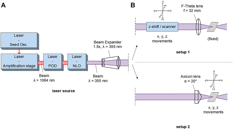
FIGURE 1. Setup for the laser ablation: (A) laser source and beam shaping for each configuration (B) 3D scanner system and F-Theta focusing lens, f = 32 mm, as the first setup, and axicon lens with 3D movements provided by a 3-axis system as the second setup [18].
The small focal length of the lens in the first configuration and the large base angle of the axicon in the second configuration are necessary to obtain a sufficiently small focused spot to achieve the desired microstructure geometry.
The x-ray grating material is a tungsten foil, with 99.95% purity and 200 μm ± 25% thickness. The requirements for the x-ray interferometric imaging are 10-microns wide slits with 20 microns periodicity (as visible in Figure 4) and 100 to 200 microns depth of a slit. The macroscopic grating surface size should be at least 4 × 4 cm2.
The laser parameters used for micromachining of tungsten foils, at the foil position for each setup, are listed in Fehler! Verweisquelle konnte nicht gefunden werden. The diameter at Full Width Half Maximum (FWHM) at the focal point is approximately 2 times smaller with the Bessel beam compared to the Gaussian beam. The difference in the pulse repetition rate between the two configurations is required due to slower movements of the 3D axis system (no possibility to use scanner with axicon lens alignment) compared to the scanner, and the requirement of the similar pulse overlap. Therefore, the pulse repetition rate is limited to about 10 kHz for the setup using the axicon lens.
Results
First, we measured the beam profile waist directly with Thorlabs Camera Beam Profiler, Model BC106N-VIS/M, with 6.5 microns pixel size, as depicted in Figure 2. For verifications of the Bessel beam creation and measurement method, we present on the left a wider Bessel beam with main peak FWHM about 40 microns, obtained with an axicon lens with basis angle 0.5°, which is sampled well and demonstrates the typical Bessel beam profile with side lobes. For our experiment we used Bessel beam obtained with an axicon lens with basis angle 20°, which should theoretically create the main peak FWHM of 0.8 microns, as discussed in the subsequent section about sub-micron hole patterns. Our measured beam with the Thorlabs Beam Profiler is not sampled sufficiently (see Figure 2B), but one can see that the FWHM of the Bessel beam main peak is approximately 6 microns or less. Due to imperfections of the axicon lens (rounding of the tip [19]), our Bessel beam main peak FWHM is wider than 1 micron, and from sharpness of edges of our micromachined 10 microns wide slit (see Figure 4B), we estimate that our Bessel beam main peak FWHM is approximately 2 microns. Also, from sharpness of edges of our micromachined 10 microns wide slit with Gaussian beam (see Figure 4A), we estimate that our Gaussian beam FWHM is approximately 4 microns.
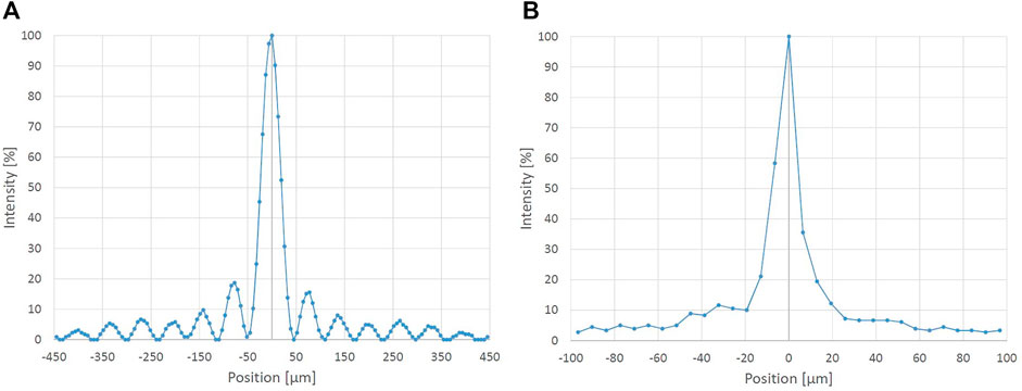
FIGURE 2. Bessel beam cross-section measured with Thorlabs Beam Profiler obtained with (A) 0.5° basis angle axicon and (B) 20° basis angle axicon, which we used in our experiments.
Further, the intensity profile propagation of the Bessel beam was measured to define the depth of focus as depicted in Fehler! Verweisquelle konnte nicht gefunden werden Figure 3. The intensity remains approximately constant over the first centimeter downstream from the axicon lens. It is in this distance that the tungsten foil has to be placed to machine the grating. After this first region, the intensity in the central peak of the Bessel beam decreases with the distance downstream from the axicon lens. In Fehler! Verweisquelle konnte nicht gefunden werden., the side lobes are visible, but not clearly distinguished within the measurement due to the CCD sensor pixel size of 6.45 × 6.45 μm2, limiting the resolution of the measurement, and low side lobe intensity.
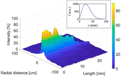
FIGURE 3. Laser beam intensity profile after the axicon lens as function of the longitudinal propagation measured with a beam profiler (CCD sensor) [18], box top right: theoretical model [19].
Figure 4 on the left, corresponds to a shallower slit obtained with Gaussian beam. Both results in Figure 4 on the left and right, are obtained with a Laser Scanning Microscope Keyence Model VHX-600. The use of a Gaussian beam with F-Theta lens implies two main disadvantages for this micromachining application. First, the wide and smoothly curved distribution of the intensity of the Gaussian profile will degrade the edge quality of the slit walls, as sharp rectangular shape is required (see Fehler! Verweisquelle konnte nicht gefunden werden., left). Second, the relatively large spot size of the focused beam (∼4 μm) compared to the beam focused with the axicon lens (∼2 μm) does not allow sharp structuring of the bottom of the slit with micron-level precision.
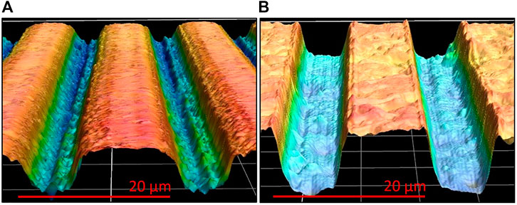
FIGURE 4. Measurement of the grating profile using a laser-scanning microscope (LSM) - (A): machining with the F-Theta lens, f = 32 mm and Gaussian beam (setup 1) and (B), machining with the 20° axicon lens (setup 2) and Bessel beam [18].
On the other hand, the axicon lens and its focused spot size enables obtaining sharper-edge walls and a relatively rectangular and homogeneous slit bottom (see Fehler! Verweisquelle konnte nicht gefunden werden., right). From those sharper machined edges and bottom, it is clear that Bessel beam has narrower FWHM compared to Gaussian beam.
The use of the axicon lens also has some disadvantages. First, a larger amount of pulse energy is required to achieve the ablation of material, due to the Bessel beam side-lobes containing significant amount of energy. The side lobes of the Bessel beam store an equivalent integrated intensity, when compared to the central peak [20]. Second, the advantage of the small focused spot diameter also means that the machining time is significantly increased. Third, for the same ablation depth and pulse overlap, two to three scanned beam passes were required with the F-Theta lens, while 12–15 passes were needed with the axicon lens. This means that for each scanned beam pass, ablation depth is less with the axicon lens, i.e., less than 1 μm ablation depth per pass is obtained with the Bessel beam, while it is several μm ablation depth obtained per pass with the F-Theta lens and Gaussian beam.
The deep machining of the tungsten foil has been then carried on with each setup of the Fehler! Verweisquelle konnte nicht gefunden werden., using the same laser source. The high aspect ratio of 1:10 could only be achieved with Gaussian beam and the F-Theta lens. The slits made with the Bessel beam after the axicon lens were limited in depth. The narrow slit in the non-transparent metal (tungsten) foil blocks the Bessel beam side lobes and due to lack of the interference effect destroys the Bessel beam profile, limiting the penetration depth. At the slit entrance, the laser parameters are adjusted so that only the top part of the main peak has enough intensity required to ablate the tungsten foil for the desired structure, while the side lobes are too weak for ablation to occur.
Ultrashort laser pulse ablation is a process with emission of particles up to several hundred nanoseconds after the laser pulse, in at least two steps [21–26]. A Helium gas flow (blow) pointed to the ablation area did not help significantly when ablating with Bessel beam. Therefore, in our case, the plasma formed by ablation with the ultrashort pulses has no significant effect on ablation. Even with the helium gas flow the achieved penetration depth is only 10–15 microns with the Bessel beam configuration. The maximum depth and profile of the slits obtained with Bessel beam is shown in Figure 4 on the right, where one could see that the top edges are sharp and uniform, while the bottom of the slit has large bumps.
On the other hand, with the Gaussian beam and the F-Theta lens, machining of deep slits did not pose any particular issues. The cross-section of the complete 200-microns deep slit in the tungsten foil, obtained with Gaussian beam (more pulses on the same spot with the same laser and focusing parameters as in Figure 4 on the left) is presented in Figure 5. Figure 5 is measured with 3D Multisensor System OGP SmartScope. At the top of the slit, the width of the slit is approximately 30 μm, but it quickly reduces the width to about 15 μm for a depth of more than 100 μm. The lower half of the tungsten sheet has a slit of approximately 15 μm. In order to achieve an aspect ratio of 1:10 with a slit width of approximately 10 μm, further tests with a tungsten sheet of 100 μm thickness should be carried out to guarantee straight side walls along the whole slit and downscaling of the slit. The other approach would be to remove the upper 100 microns of the current 200-micron thick tungsten slit with laser ablation or chemically, and straight 10-micron wide slits would remain.
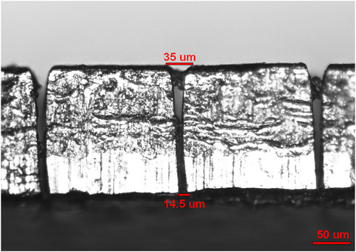
FIGURE 5. Cross-section view of the tungsten foil measured with OGP SmartScope, machined with the Gaussian beam and the F-Theta lens, obtained with the setup 1 of Fehler! Verweisquelle konnte nicht gefunden werden [18].
In addition, we wanted to investigate the smallest feature that we could obtain with an axicon lens and a Bessel beam shape.
The theoretical diameter of the Bessel beam after an axicon lens is determined by:
where the refractive index of the axicon lens material is n = 1.475, the axicon base angle is
The beam diameter is inversely proportional to the base angle of the axicon lens. A relatively large angle axicon lens is then selected to obtain a beam diameter of less than 1 μm. However, this small beam diameter limits the available depth of focus.
When the structure was produced with the axicon lens, the movement velocity of the translation axes was first defined in such a way that there was no overlap between the pulses. The results displayed in Fehler! Verweisquelle konnte nicht gefunden werden. are measured with 3D Multisensor System OGP SmartScope. After experimental trials, the diameters of multiple drilled holes were measured. The average diameter of the measured holes is:
i.e., 13% larger than the theoretical value. This deviation is explained by the fact that 10 successive pulses were required to ablate one hole in order to realize the structure, which slightly increases the diameter of the holes [27]. However, we believe that we were ablating those holes with only the tip of the main peak of the Bessel beam and the FWHM of the main peak is approximately 2 microns. The successive pulses on the same spot are obtained by successive passes with translation stages on the same spots with a pulse repetition rate of 10 kHz. This means that with axicon lens it is possible to control the tolerances of the structure more precisely than with a conventional lens. This is only possible if very precise synchronization is ensured between the 3D axis system and the laser source. However, the depth of those sub-micron diameter holes is limited to few microns.
Discussion
Generated Bessel beams contain half of the pulse energy in the side lobes [20]. However, the side lobes of Bessel beam were clipped by the narrow, non-transparent metal, high-aspect ratio slit, which prevented the Bessel beam deeper penetration, and limited the slit depth to 10–15 microns.
The fluence of setup 2 with Bessel beam shape, would be 16 times higher if the main peak would be 1 instead of 2 microns in FWHM, and all the energy would be in the central peak (2 times smaller diameter makes 4 times smaller area, plus 2 times higher peak power, plus 2 times higher energy in the main peak if half energy is not lost into side lobes). We estimate that the Bessel beam main peak FWHM is larger than theoretically predicted 1 micron, due to imperfect (rounded) tip of the axicon lens [19] and is approximately 2 microns in FWHM. The rounded axicon tip and half energy in the side lobes decrease the fluence of the Bessel beam approximately 16 times and in the end, it is similar to (only approximately 30% higher than) the fluence of the Gaussian beam with 4 microns FWHM, as stated in Table 1.

TABLE 1. Parameters used for each lens configuration with values at the machining location (setup 1 and 2) [18].
The main advantage of the Bessel beam created with an axicon lens is that one can obtain narrower FWHM and much longer depth of focus, when compared to the Gaussian focused beam with the same input beam size and wavelength. We achieved Bessel beam with the central peak FWHM of 2 μm, with a depth of focus of several centimeters. Bessel beam can increase the Rayleigh range up to 10 times [28]. This advantage of the Bessel beam is used in our experiment to create, in combination with the correct setting of the laser source in terms of pulse repetition rate, scanning speed and pulse energy, a precise structured pattern of sub-micron diameter holes in tungsten foil.
In addition, the use of ultra-short pulses has reduced heat propagation and melting and improved the slit edges [29]. We performed our investigation with a picosecond laser system, because it provides reliably a wavelength of 355 nm, enabling focusing to a smaller spot size. Future steps would include the same tests with a femtosecond UV laser.
We investigated x-ray grating micromachining by ablation with ultra-short laser pulses and compared the results obtained with a Gaussian or Bessel type beams. We studied the feasibility of the process to obtain grating lines with a few micrometer pitch, 100–200 μm depth and high quality, sharp rectangular edges. Our results demonstrate that the Gaussian type beam enables deep ablation (200 microns deep slits), with the disadvantage of limited edge sharpness of the walls and the bottom of the slit, preventing a precise structuring at 1-μm level. Figure 5 shows the structure obtained with Gaussian beam ablation, which is close to the requirements of 10 microns slit width, 200 microns depth and 20 microns periodicity. Next steps include testing for the x-ray interferometry the current structure with slits of wider top (30 microns instead of 10 microns) and 200 microns depth, with 1000s of lines creating a large-size grating. If this structure is not satisfactory, one can remove the sub-optimal top 100 microns of the 200 microns thick foil using laser ablation, or chemical methods, and use the bottom 100 microns part of the foil, which features sharp, vertical, 10 microns wide slits.
The use of a Bessel-type beam made it possible to obtain sharp edges and the structures can be more precisely controlled on 1-μm scale, owing to 2-μm waist size of the Bessel beam. We have demonstrated the realization of sub-micron hole pattern in tungsten foil. Submicron holes fabrication is not directly related to x-ray gratings, but it shows a potential of submicron structure fabrication with axicon lens and Bessel beam.
However, the sub-micron structure could not be drilled deeper than few microns with the Bessel beam. The high aspect ratio hole geometry in metals prevents the propagation of the side lobes of the beam and destroys the Bessel beam profile before reaching the targeted deeper point for ablation.
The laser instabilities to the best of our knowledge, were not an issue. The beam pointing instabilities on a short time scale (few hours), are in sub-micron level, as visible from Figure 6., where we drilled sub-micron diameter holes with multiple pulses coming back to the same spot, after multiple scans. The pulse-to-pulse energy instabilities were negligible, as they are typically in the range of 0.5% rms, and we use multiple pulses to ablate material in the same spot and drill a hole or a slit. Production time for large scale x-ray gratings (4–10 cm by 4–10 cm) will be half day or 1–2 days and it remains to be seen if pointing stability of the laser will be sufficiently good over this time frame.
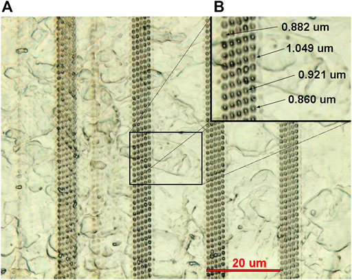
FIGURE 6. Diameters of the holes made with the axicon lens of 20°, with no overlap between the pulses. Left: structure made, right: zoom-in and diameter of the holes. The zoom-in on the right shows the area marked with black rectangle inside the left image [18].
Data Availability Statement
The original contributions presented in the study are included in the article/Supplementary Material, further inquiries can be directed to the corresponding author.
Author Contributions
BL, RH and BR contributed to the conception and design of the study. RC and BL performed the measurements. RH and BR also performed the analysis and evaluation of data. RC wrote the first draft of the manuscript and BR wrote some sections of the manuscript. All authors contributed to manuscript revision, read, and approved the submitted version.
Funding
This research is partially financially supported by Swiss Nanoscience Institute within the NanoArgovia project A13.01 NanoCreate. Portions of this work were presented at the Photonica conference in Belgrade, Serbia in 2019, poster LM1; and at the Ultrafast Optics conference in Bol, Croatia in 2019, presentation M3.3, as referenced in (30).
Conflict of Interest
The authors declare that the research was conducted in the absence of any commercial or financial relationships that could be construed as a potential conflict of interest.
Publisher’s Note
All claims expressed in this article are solely those of the authors and do not necessarily represent those of their affiliated organizations, or those of the publisher, the editors and the reviewers. Any product that may be evaluated in this article, or claim that may be made by its manufacturer, is not guaranteed or endorsed by the publisher.
References
1. Groso A, Abela R, Stampanoni M. Implementation of a Fast Method for High Resolution Phase Contrast Tomography. Opt Express (2006) 14:8103–10. doi:10.1364/oe.14.008103
2. Stampanoni M, Wang Z, Thüring T, David C, Roessl E, Trippel M, et al. The First Analysis and Clinical Evaluation of Native Breast Tissue Using Differential Phase-Contrast Mammography. Invest Radiol (2011) 46:801–6. doi:10.1097/rli.0b013e31822a585f
3. Hauser N, Wang Z, Kubik-Huch RA, Trippel M, Singer G, Hohl MK, et al. A Study on Mastectomy Samples to Evaluate Breast Imaging Quality and Potential Clinical Relevance of Differential Phase Contrast Mammography. Invest Radiol (2014) 49:131–7. doi:10.1097/rli.0000000000000001
4. Chichkov BN, Momma C, Nolte S, Alvensleben F, Tünnermann A. Femtosecond, Picosecond and Nanosecond Laser Ablation of Solids. Appl Phys A (1996) 63(2):109–15. doi:10.1007/bf01567637
5. Nolte S, Momma C, Jacobs H, Tünnermann A, Chichkov BN, Wellegehausen B, et al. Ablation of Metals by Ultrashort Laser Pulses. J Opt Soc Am B (1997) 14:2716–22. doi:10.1364/josab.14.002716
6. Ameer-Beg S, Perrie W, Rathbone S, Wright J, Weaver W, Champoux H. Femtosecond Laser Microstructuring of Materials. Appl Surf Sci (1998) 127-129:875–80. doi:10.1016/s0169-4332(97)00760-5
7. Sibbett W, Lagatsky AA, Brown CTA. The Development and Application of Femtosecond Laser Systems. Opt Express (2012) 20:6989–7001. doi:10.1364/oe.20.006989
8. Lungershausen J, Stumpp A, Ferrari A, Poulikakos D, Kurtcuoglu V. Advanced Laser Ablation for the Surface Microstructuring of Cardiovascular Implants. Eur Cell Mater (2013) 26(Suppl. 1):30. doi:10.22203/eCM
9. Garcia-Lechuga M, Utéza O, Sanner N, Grojo D. Evidencing the Nonlinearity independence of Resolution in Femtosecond Laser Ablation. Opt Lett (2020) 45:952–5. doi:10.1364/ol.382610
10. Zambon V, McCarthy N, Piché M. Material Modifications with Ultrafast Bessel Beams. In: Proceedings of the Frontiers in Optics 2009/Laser Science XXV/Fall 2009 OSA Optics & Photonics Technical Digest, OSA Technical Digest (CD); October 2009; San Jose, California United States. Washington, D.C. United States: Optical Society of America (2009). paper JTuC15. doi:10.1364/lm.2009.jtuc15
11. Mitra S, Chanal M, Clady R, Mouskeftaras A, Grojo D. Millijoule Femtosecond Micro-bessel Beams for Ultra-high Aspect Ratio Machining. Appl Opt (2015) 54:7358–65. doi:10.1364/ao.54.007358
12. Cheng H, Xia C, Zhang M, Kuebler SM, Yu X. Fabrication of High-Aspect-Ratio Structures Using Bessel-Beam-Activated Photopolymerization. Appl Opt (2019) 58:D91–D97. doi:10.1364/ao.58.000d91
13. Bhuyan MK, Courvoisier F, Lacourt P-A, Jacquot M, Furfaro L, Withford MJ, et al. High Aspect Ratio Taper-free Microchannel Fabrication Using Femtosecond Bessel Beams. Opt Express (2010) 18:566–74. doi:10.1364/oe.18.000566
14. Yao Z, Jiang L, Li X, Wang A, Wang Z, Li M, et al. Non-diffraction-length, Tunable, Bessel-like Beams Generation by Spatially Shaping a Femtosecond Laser Beam for High-Aspect-Ratio Micro-hole Drilling. Opt Express (2018) 26:21960–8. doi:10.1364/oe.26.021960
15. Brzobohatý O, Čižmár T, Zemánek P. High Quality Quasi-Bessel Beam Generated by Round-Tip Axicon. Opt Express (2008) 16:12688–700. doi:10.1364/oe.16.012688
16. Schwarz S, Rung S, Esen C, Hellmann R. Fabrication of a High-Quality Axicon by Femtosecond Laser Ablation and CO2 Laser Polishing for Quasi-Bessel Beam Generation. Opt Express (2018) 26:23287–94. doi:10.1364/oe.26.023287
17. Dudutis J, Pipiras J, Schwarz S, Rung S, Hellmann R, Račiukaitis G, et al. Laser-fabricated Axicons Challenging the Conventional Optics in Glass Processing Applications. Opt Express (2020) 28:5715–30. doi:10.1364/oe.377108
18. Carreto R, Lüscher B, Holtz R, Resan B. Laser Micromachining of Gratings for X-ray Interferometry Imaging and Sub-micron Hole Patterns. Belgrade, Serbia: Photonica (2019). Available at: http://www.photonica.ac.rs/doc18.2.2022s/posters/LM1.pdf (Accessed February 18, 2022).
19. Wu P, Sui C, Huang W. Theoretical Analysis of a Quasi-Bessel Beam for Laser Ablation. Photon Res (2014) 2(3):82–6. doi:10.1364/prj.2.000082
20. Zapata-Rodríguez CJ, Sánchez-Losa A. Three-dimensional Field Distribution in the Focal Region of Low-Fresnel-Number Axicons. J Opt Soc Am A (2006) 23:3016–26. doi:10.1364/josaa.23.003016
21. Mannion PT, Magee J, Coyne E, O’Connor GM, Glynn TJ. The Effect of Damage Accumulation Behaviour on Ablation Thresholds and Damage Morphology in Ultrafast Laser Micro-machining of Common Metals in Air. Appl Surf Sci (2004) 233(1-4):275–87. doi:10.1016/j.apsusc.2004.03.229
22. Martirosyan AE, Altucci C, Bruno A, de Lisio C, Porzio A, Solimeno S. Time Evolution of Plasma Afterglow Produced by Femtosecond Laser Pulses. J Appl Phys (2004) 96(10):5450–5. doi:10.1063/1.1803920
23. König J, Nolte S, Tünnermann A. Plasma Evolution during Metal Ablation with Ultrashort Laser Pulses. Opt Express (2005) 13(26):10597–607. doi:10.1364/opex.13.010597
24. Jaeggi B, Neuenschwander B, Schmid M, Muralt M, Zuercher J, Hunziker U. Influence of the Pulse Duration in the Ps-Regime on the Ablation Efficiency of Metals. Phys Proced (2011) 12:164–71. doi:10.1016/j.phpro.2011.03.118
25. Di Niso F, Gaudiuso C, Sibillano T, Mezzapesa FP, Ancona A, Lugarà PM. Role of Heat Accumulation on the Incubation Effect in Multi-Shot Laser Ablation of Stainless Steel at High Repetition Rates. Opt Express (2014) 22:12200–10. doi:10.1364/oe.22.012200
26. Zhang H, Zhang F, Du X, Dong G, Qiu J. Influence of Laser-Induced Air Breakdown on Femtosecond Laser Ablation of Aluminum. Opt Express (2015) 23:1370–6. doi:10.1364/oe.23.001370
27. Ni X, Wang C-y., Yang L, Li J, Chai L, Jia W, et al. Parametric Study on Femtosecond Laser Pulse Ablation of Au Films. Appl Surf Sci (2006) 253(3):1616–9. doi:10.1016/j.apsusc.2006.02.053
28. Arlt J, Garces-Chavez V, Sibbett W, Dholakia K. Optical Micromanipulation Using a Bessel Light Beam. Opt Commun (2001) 197(4-6):239–45. doi:10.1016/s0030-4018(01)01479-1
29. Leitz K-H, Redlingshöfer B, Reg Y, Otto A, Schmidt M. Metal Ablation with Short and Ultrashort Laser Pulses. Phys Proced (2011) 12:230–8. doi:10.1016/j.phpro.2011.03.128
Keywords: axicon, Gaussian beam, Bessel beam, ultrafast laser ablation, micromachining, x-ray imaging, grating, high-ascpect ratio hole drilling
Citation: Carreto R, Lüscher B, Holtz R and Resan B (2022) Towards Ultrafast Laser Micromachining of X-Ray Gratings and Creation of Sub-Micron Hole Patterns, Comparison of Results With Bessel and Gaussian Beams. Front. Phys. 10:809212. doi: 10.3389/fphy.2022.809212
Received: 04 November 2021; Accepted: 07 February 2022;
Published: 10 March 2022.
Edited by:
Kevin Chen, University of Pittsburgh, United StatesReviewed by:
Nektarios Papadogiannis, Hellenic Mediterranean University, GreeceChaitanya Kumar Suddapalli, The Institute of Photonic Sciences (ICFO), Spain
Copyright © 2022 Carreto, Lüscher, Holtz and Resan. This is an open-access article distributed under the terms of the Creative Commons Attribution License (CC BY). The use, distribution or reproduction in other forums is permitted, provided the original author(s) and the copyright owner(s) are credited and that the original publication in this journal is cited, in accordance with accepted academic practice. No use, distribution or reproduction is permitted which does not comply with these terms.
*Correspondence: Bojan Resan, Ym9qYW4ucmVzYW5AZmhudy5jaA==
 Romain Carreto
 Beat Lüscher1
 Bojan Resan