 Qiang Fu
 Feng Zhao2
- 1Institute of Space Optoelectronics Technology, Changchun University of Science and Technology, Changchun, China
- 2School of Opto-Electronic Engineering, Changchun University of Science and Technology, Changchun, China
In this paper, a heterogeneous intersection formula, a method of fusion of coordinates, and an error allocation method are introduced in order to improve the target coordinate measurement accuracy of the intersection measurement of the theodolite. Additionally, the angle measurement accuracy of the theodolite is divided into horizontal and vertical components for discussion, and the coordinate measurement accuracy of the theodolite obtained by this method is compared and analyzed. This paper first introduces the formula for coplanar intersection, then suggests the formula for fusing theodolite coordinates and error, and then verifies the accuracy of the formula through experimentation. Finally, it simulates the goniometric accuracy with the normal distribution error using MATLAB and derives the coordinate measurement accuracy using this method. The simulation results demonstrate the viability of the error distribution approach and fusion formula used for data processing in this paper.
Introduction
The photoelectric theodolite is widely used in aviation, aerospace, weapons testing, and other scientific research and military fields because of its advantages of real-time, high precision, and dynamic tracking [1–3]. To acquire the three-dimensional coordinates of the target, the aerial position of the test target is frequently measured by intersection because a single theodolite can only obtain two-dimensional coordinate information on the space target. Although there are rangeable theodolites that can complete the positioning of a single theodolite, the intersection positioning approach is still popular since it yields measurements with a higher degree of accuracy [4,5].
The modern photoelectric theodolite system was created in 1979 by Hewlett-Packard Company in the United States, which connected two HP3820A electronic theodolites to a computer to create a “real-time triangulation system.” In this system, the two electronic theodolites simultaneously align and observe the measured point, and the computer receives the angular information and calculates its coordinates [6].
The two theodolites’ lines of sight should cross at the target [7,8]. However, in actuality, the two instruments and the target create a heterogeneous straight line because of other factors like photoelectric theodolites’ structures, angle measurement precision, and different target viewing positions. The heterogeneous meeting of photoelectric theodolites has been extensively investigated in relation to dynamic target tracking measurement. However, the coordinates of the measurement site are typically approximated as the midway of the common vertical line of the heterogeneous line [1]. However, the target actually exists close to the common plumb line. In addition, when analyzing the photoelectric theodolite’s angle measurement error, the horizontal angle measurement error and the elevation measurement error are not distinguished despite the fact that they have different sizes. As a result, it is necessary to suggest methods of improvement to the coordinate distribution power coefficient and talk about the variations in the angle measurement accuracy.
This paper introduces the literature [9]in the intersection data processing of the dual photoelectric theodolites. It also introduces the concept of heterogeneous intersection. Based on [10], the influence of the photoelectric theodolite’s azimuth and elevation angle measurement accuracy is considered in the measurement of coordinate weight coefficients in a differentiated way, and an improved coordinate fusion method is proposed to analyze the influence of the angle measurement accuracy.
Theoretical basis
Coplanar intersection of dual photoelectric theodolites
The common coplanar intersection method and the common photoelectric theodolite symbols are briefly introduced in this section. The azimuth and elevation angles of the two photoelectric theodolites and the coordinates of the target and the theodolite in accordance with their geometric relationship are used to solve the two-theodolite intersection measurement problem, which yields the coordinates of the target.
The coordinate system used for the coplanar intersection of the photoelectric theodolite is shown in Figure 1, and the target position is defined as
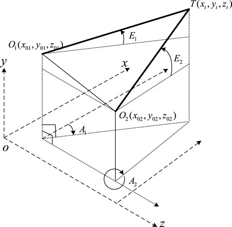
FIGURE 1. Schematic diagram of the coplanar intersection measurement.
The theoretical value of the azimuth angle of the target is shown in Eq. 1.
The theoretical value of the elevation angle of the target is shown in Eq. 2.
The subscripts 01 and 02 are used to denote the two theodolites. The relationship between the measured target coordinates and azimuth, elevation, and theodolite position is as follows:
Heterogeneous intersection of dual photoelectric theodolites
(1) Model building
The difference between the measured values of the azimuth angle and elevation angle of the target measured by the theodolite and the true value is the angle measurement accuracy, which is generally expressed by the root mean square error. As shown in Figure 2, the theodolites are located at
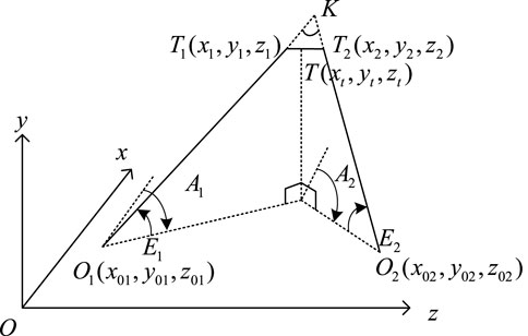
FIGURE 2. Schematic diagram of the heterogeneous intersection.
The parametric equations of the heterogeneous line
and the direction vectors of
From the fact that
Among them,
When
The coordinates of
Depending on the coordinates of the theodolite we used, the results of the calculation of the target coordinates can be divided into two forms of Eq. 6 in order to fully use the results of both measurements, and the coordinates of
where
(2) Calculation of the measurement error
From the aforementioned equations, it can be seen that the coordinate error of the target comes from the three-dimensional coordinates of the two theodolites and the measured azimuthal error
If the calculation is performed with the coordinates of only one of the two theodolites, it will bring an uneven distribution of errors. Also, when the coordinates of both theodolites are added, the calculation will take the whole error into account. Let the intersection measurement result calculated by the first theodolite be
In order to fully use the data, this paper proposes that the two sets of data measured by the two theodolites are weighted and averaged, and the weight is the reciprocal of the variance of each measurement error. This paper averages and fuses the two sets of data to obtain the improved coordinate of the target, as shown in Eqs. 15–17:
From Eq. 15, it can be seen that the measurement results are weighted by the inverse of the corresponding intersection measurement error variance. Those with a larger measurement variance have smaller weights, and those with a smaller measurement variance have larger weights so as to obtain effective fusion results.
Simulation of the positioning accuracy of the new fitting method
Experiment
This section experimentally verifies that the accuracy of the heterogeneous intersection formula and the fitting method in this paper is better than the previous coplanar formula.
Figure 3 shows the theodolite used in the experiment. As shown in Figure 4, the experimental device is mainly composed of two theodolites and an optical platform, of which the model of the theodolite is South NTS-360 (2″) and the optical platform is the Tianjin Nuolei Xinda GSZ-1-type precision optical platform. In the experiment, the leftmost side of the eight holes on the optical platform is measured, and the location of the holes is shown in Figure 4. Since the holes are evenly spaced and the height difference is very small, the leftmost side of each hole can be approximately connected to a straight line.
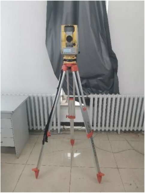
FIGURE 3. Theodolite used in the experiment (South NTS360)
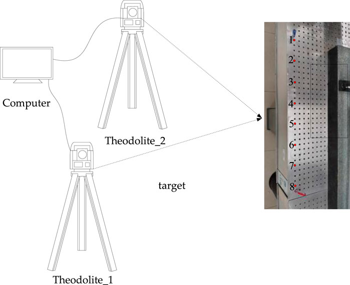
FIGURE 4. Schematic diagram of the experimental setup.
In Figure 5, 01 is theodolite 1,

FIGURE 5. Principle of the horizontal angle measurement after determining the rear-view point under the left-handed coordinate system of the theodolite.
It is necessary to establish the coordinates of the origin, total theodolite, and rear-view point and to make both total theodolites point north in order to build the global coordinate system of the two total theodolites. Both the total theodolites are made to point strictly north toward the tile seam; after choosing the total theodolite to point north, the horizontal angle is rotated by 90°; the point on the laser direct wall is chosen as the hindsight point; and the azimuth angle, height angle, and elevation angle are measured.
The coordinates of theodolite 1 and 2 were determined after measurement as (.615, 1.8, and 1.525) and (.05, 3.605, and 1.54). The measurement results are shown in Table 1, where
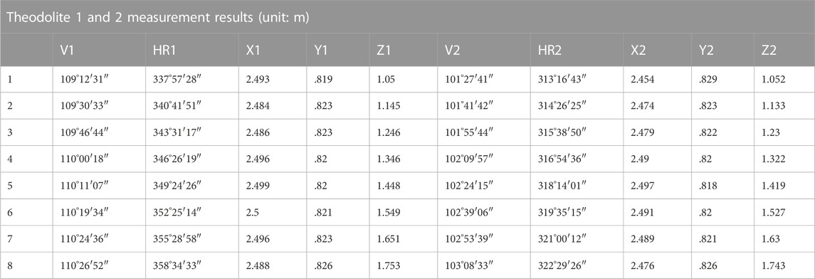
TABLE 1. Measurement results.
In Table 1, it can be seen that the measurement data are consistent with the actual data: as further to the right, the point on the platform is farther relative to the left theodolite, so the elevation angle becomes larger and the elevation angle
In the longitudinal direction, the x-coordinate has a certain tendency to change but the basic size is the same, which indicates that the platform is not perfectly vertical and not exactly in the n-direction of the theodolite; it can also be considered that the north-pointing adjustment is not accurate enough and there is a certain measurement error. Since the order of the measurement data of the theodolite is n, z, and e, which is to comply with the rules of the left-handed coordinate system, the measurement order of the latitude and longitude meter is XZY or NEY, which follows the left-handed coordinate system, so Y in the table actually refers to the height of the object and Z refers to the distance between the object and the theodolite. In the lateral direction, the z-coordinate gradually increases because the targets are all getting farther and farther relative to the origin. In fact, the y-coordinate of the measured target height should not have a tendency to change, but the y-coordinate has changed because the theodolite is not calibrated and the ground is not completely horizontal.
In the following section, according to the angles in the table, the coplanar formula and the heterogeneous formula of this paper are calculated and fused, and the difference between the calculated and actual results is observed and compared. In the calculation, the rules of the right-handed coordinate system are observed. The sequence of target coordinates is calculated using the aforementioned angles and compared with the actual coordinates to obtain the error. The calculation results show that the measurement errors (in m) of the coplanar formula and the heterogeneous formula are shown in Table 2 and the measurement accuracy is improved due to the use of the heterogeneous formula in both cases.
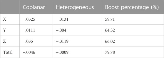
TABLE 2. Comparison of calculation results of coplanar and heterogeneous formulas.
Simulation principle
In the simulation of the angle measurement error of the theodolite, the azimuth and elevation angle measurement errors are random due to different weather and instrument accuracies at each measurement, and the distribution can be approximated as a normal distribution to simulate the actual error distribution [11].
(1) Let the target flight path be −5000 m<
(2) The accuracy of the theodolite goniometry is chosen to obtain a set of pseudorandom numbers of the observation angles. Since the error of the theodolite goniometer satisfies the normal distribution in probability
The measurement model is simulated by using the MATLAB simulation method. The method of this paper analyzes the coordinate measurement error process of the theodolite as follows:
The measurement model of the theodolite is established, for the non-rangeable theodolite, which has two internal angle measuring instruments to obtain the azimuth angle and elevation angle
where
The actual angle measurement error of a theodolite can be set from the error distribution
(3) The observation angles with errors are substituted into the formula of coplanar intersection measurement and heterogeneous intersection measurement, and the corresponding simulation samples of the coordinates of the measurement points are calculated.
(4) The samples are counted to obtain the measurement mean squared deviation of the coordinates
Simulation and discussion
Considering that the horizontal and pitch angle measurement accuracy of the theodolite may be different, this paper set the azimuth and elevation angle measurement errors of theodolites 1 and 2 as

FIGURE 6. Error influence of the angle measurement error on coordinate positioning.
As can be seen from Figure 6, the azimuth goniometric error of the second theodolite
The error range of the four goniometric errors for x, y, and z coordinates is basically the same, and the x-axis positioning error range is larger than the y and z axes, which is due to the fact that the target coordinates only change in the x-direction and the measurement baseline is approximately perpendicular to the target trajectory. Since the y and z coordinates remain unchanged during the flight of the target, the following analysis focuses on the error variation law of the x-axis.
In summary, it can be seen that the maximum error range of the x-coordinate caused by
In order to verify the reliability of the heterogeneous rendezvous theoretical model in this paper, the x, y, and z coordinate localization accuracies and the fusion localization accuracy of the target are calculated in this paper using the formulae in [12]. The calculation results are compared with the model of the reference literature and the real calculation results, and since the target positioning angle errors all obey normal distribution, the accuracy of the theoretical model can be judged according to the final positioning accuracy.
The results are shown in Table 3.
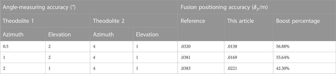
TABLE 3. Comparison of the measurement accuracy between the formulas in this paper reference.
For the case in the simulation, the target only moves in the xoz plane. The target in the case is moving in the x-direction. From the table, it can be seen that in these three groups of cases, the accuracy of this paper has a greater improvement than that of the reference, and the angle measurement accuracy of the second theodolite is set to 4″ for the azimuth measurement accuracy and 1″ for the elevation measurement accuracy to simplify the calculation. It can be seen in the table that the smaller the azimuth measurement accuracy is when the elevation angle measurement accuracy is the same, the higher the improvement of the fusion positioning accuracy in this paper over the reference, and the fusion positioning accuracy at this time is the highest in both the paper and the reference. It indicates that the azimuth angle measurement accuracy has a greater influence on target positioning under the target motion state in this case.
Figure 7 plots the x-range of the target as
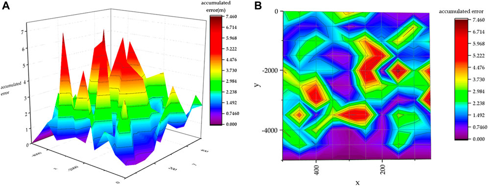
FIGURE 7. Schematic diagram of the change of the target location fusion error
Conclusion
A new method is proposed to estimate the real position of the target based on the metric vertical line of two dissimilar optical axes in space, which overcomes the principle error of treating the target as an ideal point target in the traditional intersection measurement, and the problems of unequal horizontal and vertical angle measurement accuracies due to the instrument error and external environment change, with the advantages of high positioning accuracy and easy implementation in engineering.
In this paper, we first studied the angle measuring principle of the photoelectric theodolite heterogeneous and coplanar intersection measurement formulae, and established a new measurement fusion method, conducted experiments to measure the target points, and obtained the respective measurement accuracy by formula calculation. The results show that the new measurement formula can improve the measurement accuracy, which is more accurate than the original coplanar and heterogeneous formulae and easy to implement in engineering.
Data availability statement
The original contributions presented in the study are included in the article/supplementary material. Further inquiries can be directed to the corresponding author.
Author contributions
QF and FZ simplified the idea. FZ carried out simulations and experiments. QF oversaw the project. The results were discussed and analyzed by all authors.
Funding
The study was supported by the National Natural Science Foundation of China, Astronomy Joint Fund, grant number U1731240.
Acknowledgments
The authors would like to thank the National Natural Science Foundation of China for the help in identifying collaborators for this work.
Conflict of interest
The authors declare that the research was conducted in the absence of any commercial or financial relationships that could be construed as a potential conflict of interest.
Publisher’s note
All claims expressed in this article are solely those of the authors and do not necessarily represent those of their affiliated organizations, or those of the publisher, the editors, and the reviewers. Any product that may be evaluated in this article, or claim that may be made by its manufacturer, is not guaranteed or endorsed by the publisher.
References
1. Hou HL, Li H. The method of measuring three dimensional coordinates of aircraft with photoelectric theodolite and error analysis[J]. Opto-Electronic Eng (2002) 2002(03):4–8. doi:10.3969/j.issn.1003-501X.2002.03.002
2. Fu Q, Zhao F, Chen H, Zhu R, Li Y. Space object and background polarization models and detectability analysis. Appl Sci (2022) 12(21):10714. doi:10.3390/app122110714
3. Xu M, Shi HD, Wang C, Liu Z, Fu Q, Li YC, et al. Research on the integration technology of multi-dimensional space target detection and laser communication[J]. Chin J Lasers (2021) 48(12):223–35. doi:10.3788/CJL202148.1206002
4.Technology and Industry for National Defense. Post processing method of photoelectric theodolite. Beijing: Commission of Science, Technology and Industry for National Defense.
5. Wu NW. Research on real time guidance of theodolite[D]. China: Changchun Institute of Optics, Precision Machinery and Physics, Chinese Academy of Sciences (2003).
6. Gao H. Research on principle, verification and application of non orthogonal coordinate measuring system[D]. China: Information Engineering University (2003).
7. Liu JC, Guo LH, Guan WC, Xing ZB. Quantitative prediction of theodolite intersection accuracy[J]. Opt Precision Eng (2008) 2008 (10):1822–30. doi:10.3321/j.issn:1004-924X.2008.10.006
8. Liu XW, Hu YA, Liu L. Improvement and error analysis of two station intersection measurement algorithm of photoelectric theodolite[J]. J Naval Aviation Univ (2012) 27(05):499–502. doi:10.3969/j.issn.1673-1522.2012.05.006
9. Yang ZX. Intersection measurement method and application of conventional weapon test[M]. Xi’an: Xi'an Jiaotong University Press (2010).
10. Li H, Yuan W. Spatial position estimation of the target points for two theodolites intersecting in heteroplane[J]. Fire Control and Command Control (2017) 42(04):138–41. doi:10.3969/j.issn.1002-0640.2017.04.030
11. Zhang FM, Qu XH, Ye SH. Uncertainty analysis of large size measurement based on Monte Carlo simulation[J]. Comp Integrated Manufacturing Syst (2009) 15(01):184–7+196. doi:10.13382/j.jemi.2015.03.018
Keywords: photoelectric theodolite, intersection measurement, error analysis, normal distribution, coordinate measurement and simulation
Citation: Fu Q, Zhao F, Zhu R, Liu Z and Li Y (2023) Research on the intersection angle measurement and positioning accuracy of a photoelectric theodolite. Front. Phys. 10:1121050. doi: 10.3389/fphy.2022.1121050
Received: 11 December 2022; Accepted: 27 December 2022;
Published: 10 February 2023.
Edited by:
Ben-Xin Wang, Jiangnan University, ChinaReviewed by:
Xiubin Yang, Chinese Academy of Sciences (CAS), ChinaLing Jie, Chinese Academy of Sciences (CAS), China
Copyright © 2023 Fu, Zhao, Zhu, Liu and Li. This is an open-access article distributed under the terms of the Creative Commons Attribution License (CC BY). The use, distribution or reproduction in other forums is permitted, provided the original author(s) and the copyright owner(s) are credited and that the original publication in this journal is cited, in accordance with accepted academic practice. No use, distribution or reproduction is permitted which does not comply with these terms.
*Correspondence: Qiang Fu, Y3VzdF9mdXFpYW5nQDE2My5jb20=