 Xinyang Pan
 Haitao Li
 Weijie Dong1
 Chuandeng Hu
 Bo Hou
- 1School of Physical Science and Technology and Collaborative Innovation Center of Suzhou Nano Science and Technology, Soochow University, Suzhou, China
- 2Department of Integrated Technology and Control Engineering, School of Aeronautics, Northwestern Polytechnical University, China
- 3Shenzhen Fantwave Tech Co., Ltd, Shenzhen, China
- 4Key Laboratory of Modern Optical Technologies of Ministry of Education and Key Lab of Advanced Optical Manufacturing Technologies of Jiangsu Province, Suzhou, China
We study the dispersions of the guided modes in the continuous uniaxial crystal slab waveguide and engineer their degeneracies through dielectric anisotropy. By switching the uniaxial positivity and negativity, we can obtain distinctive nodal types, point and line, for the lowest degeneracy in frequency. The mirror symmetry protections,
Introduction
Recently, a research focus is concentrated on nodal degeneracy in band diagrams in periodical structures [1–5], such as quantum materials, photonic crystals, and phononic crystals, because new physics and novel applications are anticipated arising from peculiar band degeneracies including point degeneracy [6–16], line/loop degeneracy [17–28], nodal chain degeneracy [29–31], nodal surface degeneracy [32, 33] and so on.
Band degeneracy is generally enforced by symmetry in the physical system. It is well known that photonic guided waves in confined structures can be classified into transverse electric (TE) and transverse magnetic (TM) modes in terms of mirror symmetry [our meanings of “TE” and “TM” adapted to classical waveguide theory, see [34]. Taking an example of an isotropic dielectric slab waveguide, both modes evolve out from the light cone in free space, and their dispersion curves are rapidly asymptotic to the light cone in dielectrics as propagation constant increasing. Because of the asymptotic parallelism, the TE and TM dispersions cross rarely to form the degeneracy beyond the free space light cone, which is schematically depicted in Figure 1B. On the other hand, the slopes of the TE and TM modes in the dispersion diagram can be tailored in a polarization-distinguishable way through introducing the uniaxial anisotropy to the dielectric slab. The tailoring mechanism is rooted on the refractive index difference which is manifested likewise in the propagation of ordinary and extra-ordinary light in a uniaxial bulk crystal [35], seeing the index ellipsoid in Figure 1.

FIGURE 1. Schematics for the index ellipsoids (upper row) in a uniaxial bulk crystal where the optical axis
In the study, we start with an isotropic dielectric slab, where TE and TM modes are not degenerate. By changing the dielectric constant into the uniaxial permittivity tensor and tuning the component of the tensor along the propagation direction, we show the slope of TM modes can either increase or decrease significantly while maintaining the slope of TE modes, which corresponds to the positively and negatively uniaxial anisotropy, respectively. Thus, the crossing between TE and TM modes can be engineered, as illustrated in Figure 1. Furthermore, the mirror symmetry along the out-of-slab direction imposes an extra enforcement on the degeneracy and leads to distinctive nodal types, Dirac point (DP) and Dirac line (DL), in the positive and negative uniaxial cases for the lowest degeneracy in frequency.
Guided mode in uniaxial crystal slabs
Here, we consider a two-dimensional (2D) infinite (along y- and z-directions), uniaxial crystal slab (finite thickness d = 2 mm in the x-direction) with non-magnetic permeability (
where
where
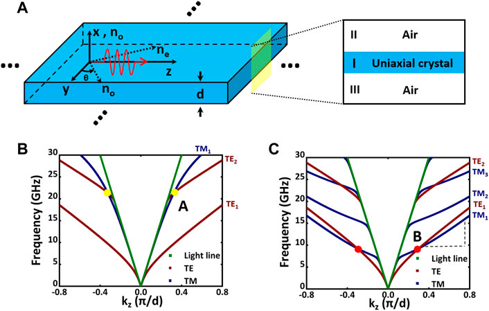
FIGURE 2. (A) The schematic picture of the anisotropic dielectric slab waveguide, where
and for TM mode:
Above, Eqs 4, 6 are the dispersion relation in regime I, α is the imaginary part of perpendicular component of wave vector in theregime
For concreteness, we choose
It is noted that the first-order TM mode (TM1) crosses with the second-order TE mode (TE2) for the negatively uniaxial case (
Type-II Dirac degeneracy in uniaxial crystal slabs
In order to exhibit the complete dispersion structure around the degenerate points, we need calculate the band diagram
in which
Then, we assume that the waves still propagate along the z-direction and express the electric fields and magnetic fields in different regions. Because the mirror symmetry
We first analyze the degenerate point
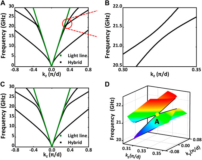
FIGURE 3. Type-II Dirac point in the dispersion diagram of the negatively uniaxial crystal slab when
Next, let’s focus our attention on the degenerate point
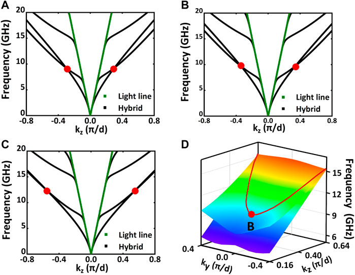
FIGURE 4. Type-II Dirac line in the dispersion diagram of the positively uniaxial crystal slab when
It is also noted from Figure 4C that the two bands, responsible for the Dirac line, almost coincide with each other when
Discussions
When investigating the propagation of the guided modes along the direction perpendicular to the optical axis (e.g., the propagation along y-axis while the optical axis being z-axis, and the mirror symmetry
In addition, we present a microwave metamaterial design which approximates at lower frequencies a positively uniaxial crystal with dispersive permittivity component, and the band degeneracy shows the similarity to and the difference from the case of the continuous crystal slab (see Section E in Supplementary Materials).
Conclusion
In conclusion, by controlling positivity/negativity of the refractive index ellipsoid, we can obtain the nodal point and nodal line degeneracies for the guided modes on the uniaxial crystal slab waveguide. Furthermore, the point and line characteristics and their connections with the refractive index ellipsoid can be swapped through switching the propagation direction. Our results link the band degeneracy with positivity/negativity of the uniaxial crystal, and provide a new approach to regulate the topology of degeneracy in 2D photonic bands.
Data availability statement
The original contributions presented in the study are included in the article/supplementary material, further inquiries can be directed to the corresponding author.
Author contributions
BH conceived and supervised the research; XP performed the research; HL, WD, XZ, KX, CH, and GW assisted in analyzing the data; and BH, XP, and HL wrote the manuscript.
Funding
This work was supported by the Natural Science Foundation of China (NSFC) (Grant No. 12074279), the Major Program of Natural Science Research of Jiangsu Higher Education Institutions (Grant No.18KJA140003), and the Priority Academic Program Development (PAPD) of Jiangsu Higher Education Institutions.
Conflict of interest
Chuandeng Hu was employed by Shenzhen Fantwave Tech Co., Ltd
The remaining authors declare that the research was conducted in the absence of any commercial or financial relationships that could be construed as a potential conflict of interest.
Publisher’s note
All claims expressed in this article are solely those of the authors and do not necessarily represent those of their affiliated organizations, or those of the publisher, the editors and the reviewers. Any product that may be evaluated in this article, or claim that may be made by its manufacturer, is not guaranteed or endorsed by the publisher.
Supplementary material
The Supplementary Material for this article can be found online at: https://www.frontiersin.org/articles/10.3389/fphy.2022.1095669/full#supplementary-material
References
1. Armitage NP, Mele EJ, Vishwanath A. Weyl and Dirac semimetals in three-dimensional solids. Rev Mod Phys (2018) 90:015001. doi:10.1103/revmodphys.90.015001
2. Li S, Yu Z-M, Yao Y, Yang SA. Type-II topological metals. Front Phys (2020) 15(4):43201. doi:10.1007/s11467-020-0963-7
3. Lu L, Joannopoulos JD, Soljačić M. Topological photonics. Nat Photon (2014) 8:821–9. doi:10.1038/nphoton.2014.248
4. Kim M, Jacob Z, Rho J. Recent advances in 2D, 3D and higher-order topological photonics. Light Sci Appl (2020) 9:130. doi:10.1038/s41377-020-0331-y
5. Park HD, Gao W, Zhang X, Oh SS. Nodal lines in momentum space: Topological invariants and recent realizations in photonic and other systems. Nanophotonics (2022) 11(11):2779–801. doi:10.1515/nanoph-2021-0692
6. Lu L, Wang Z-Y, Ye D-X, Ran L-X, Fu L, Joannopoulos JD, et al. Experimental observation of Weyl points. Science (2015) 349:622–4. doi:10.1126/science.aaa9273
7. Gao W, Yang B, Lawrence M, Fang F, Béril B, Zhang S. Photonic Weyl degeneracies in magnetized plasma. Nat Commun (2016) 7:12435. doi:10.1038/ncomms12435
8. Yang B, Guo Q, Tremain B, Barr LE, Gao W, Liu H, et al. Direct observation of topological surface-state arcs in photonic metamaterials. Nat Commun (2017) 8:97. doi:10.1038/s41467-017-00134-1
9. Yang B, Guo Q, Tremain B, Liu R, Barr LE, Yan Q, et al. Ideal Weyl points and helicoid surface states in artificial photonic crystal structures. Science (2018) 359:1013–6. doi:10.1126/science.aaq1221
10. Qiu P, Qiu W, Lin Z, Chen H, Ren J, Wang J-X, et al. Double Dirac point in a photonic graphene. J Phys D: Appl Phys (2017) 50:335101. doi:10.1088/1361-6463/aa7bc2
11. Xiao M, Lin Q, Fan S. Hyperbolic Weyl point in reciprocal chiral metamaterials. Phys Rev Lett (2016) 117:057401. doi:10.1103/physrevlett.117.057401
12. Yang Y, Gao Z, Feng X, Huang Y-X, Zhou P, Yang SA, et al. Ideal unconventional Weyl point in a chiral photonic metamaterial. Phys Rev Lett (2020) 125:143001. doi:10.1103/physrevlett.125.143001
13. Liu G-G, Zhou P, Yang Y, Xue H, Ren X, Lin X, et al. Observation of an unpaired photonic Dirac point. Nat Commun (2020) 11:1873. doi:10.1038/s41467-020-15801-z
14. Luo L, Deng W, Yang Y, Yan M, Lu J, Huang X, et al. Observation of quadruple Weyl point in hybrid-Weyl phononic crystals. Phys Rev B (2022) 106:134108. doi:10.1103/physrevb.106.134108
15. Huang X, Lai Y, Hang ZH, Zheng H, Chan CT. Dirac cones induced by accidental degeneracy in photonic crystals and zero-refractive-index materials. Nat Mater (2011) 10:582–6. doi:10.1038/nmat3030
16. Xu C, Ma G, Chen Z-G, Luo J, Shi J, Lai Y, et al. Three-dimensional acoustic double-zero-index medium with a fourfold degenerate Dirac-like point. Phys Rev Lett (2020) 124:074501. doi:10.1103/physrevlett.124.074501
17. Lin JY, Hu NC, Chen YJ, Lee CH, Zhang X. Line nodes, Dirac points, and Lifshitz transition in two-dimensional nonsymmorphic photonic crystals. Phys Rev B (2017) 96:075438. doi:10.1103/physrevb.96.075438
18. Yang S-Y, Yang H, Derunova E, Parkin SSP, Yan B, Ali MN. Symmetry demanded topological nodal-line materials. Adv Phys (2018) 3:1414631. doi:10.1080/23746149.2017.1414631
19. Feng B, Fu B, Kasamatsu S, Ito S, Cheng P, Liu C-C, et al. Experimental realization of two-dimensional Dirac nodal line fermions in monolayer Cu2Si. Nat Commun (2017) 8:1007. doi:10.1038/s41467-017-01108-z
20. Feng B, Zhang R-W, Feng Y, Fu B, Wu S, Miyamoto K, et al. Discovery of Weyl nodal lines in a single-layer ferromagnet. Phys Rev Lett (2019) 123:116401. doi:10.1103/physrevlett.123.116401
21. Wang S-S, Yu Z-M, Liu Y, Jiao Y, Guan S, Sheng X-L, et al. Two-dimensional nodal-loop half-metal in monolayer MnN. Phys Rev M (2019) 3:084201. doi:10.1103/physrevmaterials.3.084201
22. You J-Y, Chen C, Zhang Z, Sheng X-L, Yang SA, Su G. Two-dimensional Weyl half-semimetal and tunable quantum anomalous Hall effect. Phys Rev B (2019) 100:064408. doi:10.1103/physrevb.100.064408
23. Gao W, Yang B, Tremain B, Liu H, Guo Q, Xia L, et al. Experimental observation of photonic nodal line degeneracies in metacrystals. Nat Commun (2018) 9:950. doi:10.1038/s41467-018-03407-5
24. Qiu H, Qiu C, Yu R, Xiao M, He H, Ye L, et al. Straight nodal lines and waterslide surface states observed in acoustic metacrystals. Phys Rev B (2019) 100:041303. doi:10.1103/physrevb.100.041303
25. Deng W, Lu J, Li F, Huang X, Yan M, Ma J, et al. Nodal rings and drumhead surface states in phononic crystals. Nat Commun (2019) 10:1769. doi:10.1038/s41467-019-09820-8
26. Xiong Z, Zhang R-Y, Yu R, Chan CT, Chen Y. Hidden symmetry enforced nexus points of nodal lines in layer-stacked dielectric photonic crystals. Light Sci Appl (2020) 9:176. doi:10.1038/s41377-020-00382-9
27. Hu M, Zhang Y, Jiang X, Qiao T, Wang Q, Zhu S, et al. Double-bowl state in photonic Dirac nodal line semimetal. Light Sci Appl (2021) 10:170. doi:10.1038/s41377-021-00614-6
28. Deng W-M, Chen Z-M, Li M-Y, Guo C-H, Tian Z-T, Sun K-X, et al. Ideal nodal rings of one-dimensional photonic crystals in the visible region. Light Sci Appl (2022) 11:134. doi:10.1038/s41377-022-00821-9
29. Yan Q, Liu R, Yan Z, Liu B, Chen H, Wang Z, et al. Experimental discovery of nodal chains. Nat Phys (2018) 14(5):461–4. doi:10.1038/s41567-017-0041-4
30. Wang Y, Zhou X, Li S, Zhang W, Hu C, Lu W, et al. Flatness and boundness of photonic drumhead surface state in a metallic lattice. Sci Rep (2021) 11:8684. doi:10.1038/s41598-021-88004-1
31. Wu X, Fan H, Liu T, Gu Z, Zhang R-Y, Zhu J, et al. Topological phononics arising from fluid-solid interactions. Nat Commun (2022) 13:6120. doi:10.1038/s41467-022-33896-4
32. Xiao M, Ye L, Qiu C, He H, Liu Z, Fan S. Experimental demonstration of acoustic semimetal with topologically charged nodal surface Sci. Adv. (2020) 6:eaav2360.
33. Yang Y, Xia J-P, Sun H-X, Ge Y, Jia D, Yuan S-Q, et al. Observation of a topological nodal surface and its surface-state arcs in an artificial acoustic crystal. Nat Commun (2019) 10:5185. doi:10.1038/s41467-019-13258-3
34. Joannopoulos JD, Meade RD, Johnson SG, Joshua N. Photonic crystals: Molding the flow of light. 2nd ed. Princeton, NJ: Princeton University Press (2011).
37.ROGERSPCB MAIN (2020). Rogers laminates in stock. Available at: https://www.rogerspcb.com.cn/.
38. Hu C, Li Z, Tong R, Wu X, Xia Z, Wang L, et al. Type-II Dirac photons at metasurfaces. Phys Rev Lett (2018) 121:024301. doi:10.1103/physrevlett.121.024301
39. Li H, Hu C, Zhou X, Lu W, Hou B, Wen W. Conical diffraction from type-II Dirac point at metasurfaces. EPL (2020) 130:17007. doi:10.1209/0295-5075/130/17007
Keywords: nodal line, nodal points, uniaxial crystal, topological transformation, band degeneracy, symmetry, guided mode
Citation: Pan X, Li H, Dong W, Zhou X, Xing K-A, Hu C, Wang G and Hou B (2023) Nodal degeneracy of guided modes in uniaxial crystal slabs. Front. Phys. 10:1095669. doi: 10.3389/fphy.2022.1095669
Received: 11 November 2022; Accepted: 15 December 2022;
Published: 06 January 2023.
Edited by:
Zhiwei Guo, Tongji University, ChinaReviewed by:
Biao Yang, National University of Defense Technology, ChinaXiao-Dong Chen, Sun Yat-sen University, China
Copyright © 2023 Pan, Li, Dong, Zhou, Xing, Hu, Wang and Hou. This is an open-access article distributed under the terms of the Creative Commons Attribution License (CC BY). The use, distribution or reproduction in other forums is permitted, provided the original author(s) and the copyright owner(s) are credited and that the original publication in this journal is cited, in accordance with accepted academic practice. No use, distribution or reproduction is permitted which does not comply with these terms.
*Correspondence: Bo Hou, aG91Ym9Ac3VkYS5lZHUuY24=