 Xinxing Guo1,2
 Bo Liu1,2Weicheng Kong1,2Honglei Quan1,2Yucan Zhang1,2Tao Liu1*
 Ruifang Dong1
 Shougang Zhang1
- 1National Time Service Centre, Chinese Academy of Sciences, Xi’an, China
- 2University of Chinese Academy of Sciences, Beijing, China
In this paper, a high-precision bidirectional time-transfer system over a single fiber based on wavelength-division multiplexing and time-division multiplexing (SFWDM-TDM) is proposed, which combines the advantages of wavelength-division multiplexing and time-division multiplexing. It uses two dense wavelength-division channels to effectively suppress the problem of optical fiber reflection. At the same time, the time-division multiplexing method is used in combination with sampling and holding the time to complete the multi-user task. In hardware, we optimized the carrier processing and the high-precision time-delay control module of the SFWDM-TDM system to complete high-precision time-transfer equipment. In software and algorithm, the optical fiber time-interval measurement method and measurement times are optimized, and the SFWDM-TDM system reaches a synchronization accuracy of 8.9 ps at 1 s. Finally, a real-time detection mechanism with self-recovery ability is added to the system. This lays the foundation for a reliable, long-distance, high-precision, and multi-user mode optical fiber time- and frequency-transfer network.
Introduction
The accuracy of time and frequency directly determines the accuracy of navigation, positioning, and time service. They also determine the autonomous operation capability of satellite navigation systems [1, 2]. The existing time-transfer system includes a network, global navigation satellite systems (GNSSs), optical fiber, and other schemes [3, 4]. Due to the stability and abundant resources of optical fibers, the optical fiber time-transfer technology has attracted extensive attention from scientists. The development of optical fiber time-transfer equipment will provide time signals and technical support for major scientific and technological facilities and also meet the needs of rapid economic and social development. The application range of high-precision time and frequency has penetrated from basic research to the engineering technology application field, which is related to many important departments of the national economy and the people’s livelihood [5–7].
There is no need to reprocess the time service signal when using wavelength-division multiplexing (WDM) technology, especially the all-optical relay method. The round-trip channel has a high degree of consistency, which is conducive to eliminating the asymmetry of the round-trip signal delay. It is one of the time-transfer methods with the highest time synchronization accuracy [8, 9]. In 2013, the long-term stability of the optical fiber time synchronization experiment was less than 20 ps in the 540-km fiber link test at the Paris Observatory, France [10].In 2019, Cheng presented an optical fiber time-transfer scheme through the optical supervisory channel (OSC) in WDM systems [11]. In 2021, the National Time Service Center demonstrated a WDM-based system for simultaneously delivering ultrastable optical frequency reference, 10 GHz microwave frequency reference, and one pulse per second (1 PPS) time signal via a 50-km fiber network [12]. Also, Shanghai Jiaotong University demonstrated the time synchronization system of two-way time-division multiplexing on the same fiber and same wave transfer was used on a field optical fiber link with a length of about 60 km, and the stability is less than 16 ps/s and 7 ps/10000 s [13]. Also, it proposed a BTDM-SFSW system to overcome the influence of backscattering [14].
This paper proposes a high-precision bidirectional time-transfer system over a single fiber based on the wavelength-division multiplexing and time-division multiplexing (SFWDM-TDM) system, which combines the advantages of wavelength-division multiplexing and time-division multiplexing. It uses two dense wavelength-division channels to effectively suppress the problem of optical fiber reflection. At the same time, the time-division multiplexing method is used in combination with sampling and holding the time to complete the multi-user task. Then, in hardware, we optimized the carrier processing and the high-precision time-delay control module of the SFWDM-TDM system to complete high-precision time-transfer equipment. The phase difference value is measured using the phase detector of hardware in performing the comparison process. The phase difference value will be processed and calculated by software. Software calculates the current output phase error in combination with hardware parameters, which can convert it to the value of the phase shift by operating the DAC chip. Hardware and software complete the phase compensation function together. In terms of software and algorithm, the optical fiber time-interval measurement method and measurement times are optimized, and the SFWDM-TDM system reaches 8.9 ps at 1 s. Finally, a real-time detection mechanism with self-recovery ability is added to equipment, which lays the foundation for a reliable, long-distance, high-precision, and multi-user optical fiber time- and frequency-transfer network.
System principle of the single fiber based on wavelength-division multiplexing and time-division multiplexing
In the long-distance time transfer of the SFWDM-TDM system, the two-way time comparison method is adopted. The basic schematic diagram of the SFWDM-TDM system is shown in Figure 1. The time and frequency signals are output by the clock source to the local equipment at local site A. The local site loads the 10 MHz signal, 1 PPS time signal, and the time difference data after comparison to the output laser through the encoder unit. Also, the output wavelength of laser 1 is λ1. TDC stands for measuring the signals at both sides of the link using time interval counters. λ1 is the wavelength of the fiber forward propagation. Additionally, λ2 is the wavelength of the fiber backward propagation. The output light of the laser, as the downlink optical signal, passes through the dense wavelength-division multiplexer (DWDM) and optical fiber and reaches equipment B and C of the remote site. The photodetector of the local site detects and converts the optical signal returned from the remote site to obtain the electrical signal. Then, TDC of local site A measures the time difference between the time signal output and the time source, which provides comparison data
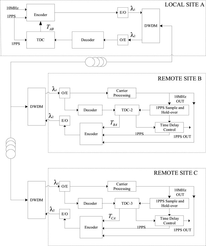
FIGURE 1. Schematic diagram of the SFWDM-TDM system.
The equipment in the remote site receives the optical signal from the local site through the photodetector to obtain the electrical signal, which decodes the time and frequency signal and the comparison data from the local site. The carrier processing unit has the functions of carrier recovery and time-keeping oscillation. The time-keeping oscillator is tamed by the time and frequency signal from the local site. The TDC-2 unit measures the time delay between the 1 PPS signal from the local site and the 1 PPS signal held by the remote site through the carrier processor to obtain the time difference
The high-precision ground-based time service system not only needs long-distance, high-precision optical fiber time synchronization but also needs a flexible and reasonable networking mode. Therefore, the optical fiber time transfer has developed a multi-user synchronization scheme based on the single fiber, which is suitable for the optical fiber network. The local site polls each remote site through time-division multiplexing. The equipment switches the optical switch through the command while amplifying the optical signal. When the local site receives the optical signal from the remote site equipment B and C, a two-way time comparison link is successfully established, which will achieve high-precision optical fiber time synchronization for long-distance multi-user.
The operation process of different sites is the same as that of remote site B, including remote site C. They can be expressed as follows:
where
The time-transfer delay of the transmitting and receiving equipment can be measured and compensated in advance. The formula shows that the remote site devices in the SFWDM-TDM system and the local site devices do not affect each other when calculating the time delay of each device. When the optical fiber bidirectional links are completely symmetrical, the sum of the bidirectional link delay can be considered
The time transfer in this paper measures and compensates the total delay of the optical fiber link accurately. It also corrects the time delay difference of the system to ensure the uncertainty of time transfer. In addition, the impact of the asymmetry introduced by bidirectional wavelength inconsistency on the uncertainty of time transfer is suppressed by dispersion deviation automatic compensation [15].
Realization and experiment analysis
The 1 PPS signal is regenerated in the remote site signal with high stability by using the 10 MHz signal output from frequency transmission. It allows the pulse edge of the regenerated 1 PPS signal track the pulse edge of the 1 PPS signal output by the SFWDM-TDM system, which can ensure that the regenerated 1 PPS signal has good stability and uncertainty at the same time. The 1 PPS sample and hold-over module ensure that each remote site device can use the time slot to keep up time and complete multi-user tasks when the system performs time-division multiplexing.
Carrier processing and the time-delay control module
In terms of hardware, a carrier processing module based on the phase-locked loop (PLL) is designed, as shown in Figure 2. The carrier processing module is a delay controller based on the phase-locked loop. The phase difference between the input 10 MHz signal and the output 10 MHz signal can be controlled by setting the phase-shift setting voltage. The phase difference between the 10 MHz signal output by a voltage-controlled crystal oscillator (VCXO) and the 10 MHz reference clock signal input from the local site is measured through a linear phase detector (PD). The phase difference is converted into a voltage signal through a loop low-pass filter. This voltage signal is compared with the phase-shifting setting voltage through an error comparator to obtain the error voltage of the difference between the setting phase and the actual phase. This error voltage controls the voltage control terminal of VCXO through the proportional integral circuit so that the phase difference between the 10 MHz signal output by the VCXO and the 10 MHz reference clock signal input from the local site is kept at the phase difference corresponding to the phase-shift setting voltage, which can realize the phase setting. The difference between this paper and other related works is the phase-shifting voltage that can be set. For the frequency control of 10 MHz of a VCXO, the variation range of control voltage is 0–3.3 V. Also, 0.825 V is set as the phase-shifting setting voltage in this scheme.
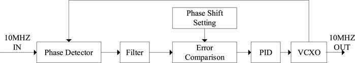
FIGURE 2. Schematic diagram of the carrier processing module.
The basic principle of phase-locked phase-shifting based on PLL is to adjust the phase slightly by changing the phase-shifting voltage. The control stability of the time-delay control module reaches 8 ps, and the control resolution is 2 ps. The time-delay control module is based on the phase-locked loop phase-shifting technology. The phase-shifting range can reach one cycle of the phase detection frequency. The periodic phase shift realized by an FPGA can provide a wide-range time-delay control. However, if a 10 MHz signal is used as the reference clock of an FPGA, the phase discrimination frequency here is 10 MHz, so it can reach 100 ns. For a phase difference of 1 PPS less than 100 ns, a digital PID is used to control the time PLL. The resolution of phase-shifting is determined by the resolution of the phase-shifting control voltage. With a 16-bit digital-to-analog converter (DAC), a 1.5 ps delay control resolution can be achieved.
The test device of the precision time-delay control module, which is composed of the PLL, is shown in Figure 3.
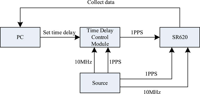
FIGURE 3. Test device of the precision time-delay control module.
AFG31052 produced by Tektronix is used as a signal source to generate a 10 MHz frequency signal and a 1 PPS time signal. These are input to SR620 produced by Stanford which is used as the reference frequency to stop signals. The signal source output another homologous 1 PPS signal, which was input to the local site of the SFWDM-TDM system. After the signal reached the remote site of the SFWDM-TDM system through a 50-km-long fiber coil, a 1 PPS signal was generated as the start signal of the SR620. The data on the time-delay control are set, and the measurement data on SR620 are collected by the PC.
The PC collects SR620 data for 5 min continuously. It records the measured average value as the measured time-delay value. The PC changes the value of the set time-delay control. Also, the data on SR620 are listed in Table 1.
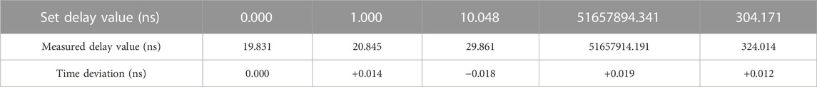
TABLE 1. Experimental data of the time-delay control module.
When the value of delay control is set to 0.000 ns, the device has a system error of 19.831 ns. It is mainly introduced by the line delay, chip delay, and the SR620 measurement deviation. After deducting the influence of these system deviations, the time deviation of the measurement is calculated to be within ± 20 ps. The value is equivalent to the non-linearity error introduced by the SR620 measurement.
Algorithm optimization
The experimental test is carried out according to Figure 1. In the remote site compensation scheme, the method of time bidirectional comparison is used. The comparison process obtains the data of time delay. Then, the time delay is controlled at the remote site, which makes it possible for a local site to synchronize multiple remote sites. In order to improve the measurement resolution and accuracy, this paper carries out multiple measurements and averages in the situation of the existing test system. The more the measurement samples are used for statistical averaging, the closer the average value is to the true value. If the system is sampled N times at the same time interval, the time accuracy after averaging can be improved to approximately 1/(√ N). In this paper, the number of 1 PPS measurements is increased by 10 times to 10 PPS for measurement. Also, the indicators conform to the 1/(√ 10) relationship.
As shown in Figure 4, the time-delay fluctuation before and after the increase in measurement times for the SFWDM-TDM system is compared. According to the actual test results of a single 50-km coiled fiber, with 1 Hz for the first time of measurement, the peak-to-peak value before algorithm improvement is about 300 ps, and the standard deviation (SD) is calculated as 65.6 ps. The peak-to-peak value of the equipment after algorithm improvement is around 80 ps with 10 Hz for the 10th time of measurement, and the SD value is 13.0 ps. The comparison of TDEV before and after algorithm improvement is shown in Figure 5. The TDEV calculation result of 1 Hz is 28.1ps@s, and the TDEV calculation result of 10 Hz is 8.9ps@s. The experimental results show that single equipment conforms to the theoretical calculation. The stability has been significantly improved after algorithm optimization.
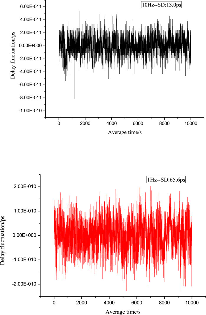
FIGURE 4. Delay fluctuation before and after algorithm improvement.
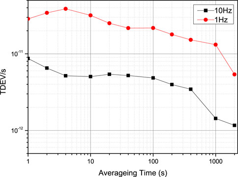
FIGURE 5. Comparison chart of TDEV before and after algorithm improvement.
The ADEV of the 10 MHz transmission reaches MS40RS0xMUAxcw== and Mi41RS0xMkAxMHM= when the testing time is 10000 s, as shown in Figure 6.
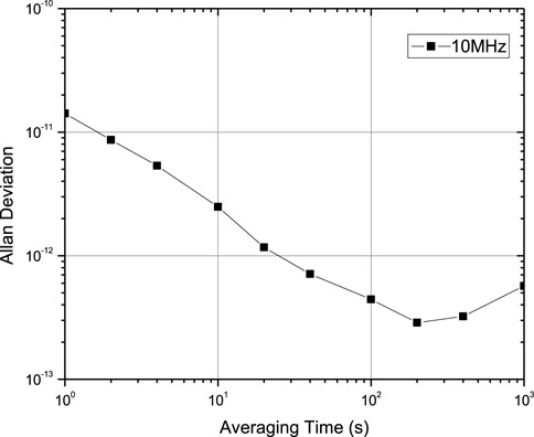
FIGURE 6. ADEV of 10 MHz.
Multi-user experiment
The 1 PPS sample and hold-over unit can track or hold the 1 PPS input signal. The 1 PPS sample and hold-over circuit are used to complete multi-user experiments. When the time and frequency signals transfer from the local site device to a remote site device, other remote site devices use the sample and hold-over system composed of OCXO, which can keep up time to ensure that the system does not deteriorate. The SFWDM-TDM system can be set to 10 remote sites. In this paper, TDEVs are obtained by sampling and comparing the delay fluctuation of remote site device 1 and remote site device 10. As shown in Figure 7, the TDEV of remote device 10 is 8.9E-12@s and 4.5ps@10s. The TDEV of remote device 1 is 8.7ps@s and 3.1ps@10s. The feasibility of SFWDM-TDM proposed by multi-users is verified in this paper, which lays a foundation for longer distance transmission.

FIGURE 7. TDEV of the 1 PPS time transfer at different remote sites.
Self-recovery capability of equipment
The system also introduces the self-recovery design of the device when power supply is restored. The device self-recovery of the system was also tested, as shown in Figure 8. It can be seen from the data that the 1 PPS time signal output by the remote site under the power failure status deviates significantly from the 1 PPS time signal of the local site. The reason is that the remote site cannot receive the signal from the local site. The remote site relies on the crystal oscillator in the remote site to keep up time when equipment is powered off. So, the 1 PPS time signal deviates in one direction. The SFWDM-TDM system will automatically recover in about 20 s when power supply of equipment recovers after the 7200 s power outage. Also, the deviation from the 1 PPS signal before power outage is only 20 ps. The self-recovery capability of the equipment is verified, which provides a basis for the robustness of the system.
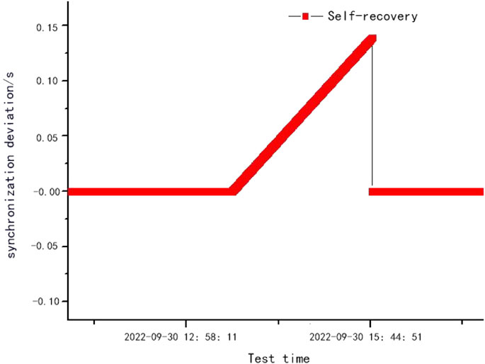
FIGURE 8. Self-recovery experiment when power supply is restored.
Conclusion
The SFWDM-TDM system developed in this paper adopts the scheme of occupying two wavelengths with dense wavelength division. It simultaneously transfers 1 PPS and 10 MHz signals, which use time-division multiplexing to achieve multi-user, long-distance, and high-precision optical fiber time synchronization. The scheme of using two dense wavelength-division channels can effectively suppress the problem of optical fiber reflection. The next step will be continued to improve device consistency and the indicators of the time-interval measurement module.
Data availability statement
The original contributions presented in the study are included in the article/Supplementary Material; further inquiries can be directed to the corresponding author.
Author contributions
Conceptualization, XG and TL; software, XG and HQ; validation, BL, WK, RD, and ZZ; formal analysis, WK; data curation, HQ; writing—original draft preparation, YZ; writing—review and editing, RD; visualization, XG; supervision, TL; funding acquisition, SZ. All authors have read and agreed to the published version of the manuscript.
Funding
This work was supported by the National Key Research and Development Program of China (2016 YF-F0200200), the National Natural Science Foundation of China (NSFC) (11803041, 61127901, and 91636101), the Strategic Priority Research Program of the Chinese Academy of Sciences (CAS) (XDB21003400000), and the Key Research and Development Plan of Guangdong Province (Grant No. 2018B030325001).
Conflict of interest
The authors declare that the research was conducted in the absence of any commercial or financial relationships that could be construed as a potential conflict of interest.
Publisher’s note
All claims expressed in this article are solely those of the authors and do not necessarily represent those of their affiliated organizations, or those of the publisher, the editors, and the reviewers. Any product that may be evaluated in this article, or claim that may be made by its manufacturer, is not guaranteed or endorsed by the publisher.
References
1. Bartels A, Diddams SA, Oates CW, Wilpers G, Bergquist JC, Oskay WH, et al. Femtosecond-laser-based synthesis of ultrastable microwave signals from optical frequency references. Opt Lett (2005) 30(6):667–9. doi:10.1364/ol.30.000667
2. Marion H, Pereira DSF, Abgrall M, Zhang S, Sortais Y, Bize S, et al. Search for variations of fundamental constants using atomic fountain clocks. Phys Rev Lett (2003) 90(15):150801. doi:10.1103/physrevlett.90.150801
3. DeCamp MF, Reis DA, Bucksbaum PH, Adams B, Caraher JM, Clarke R, et al. Coherent control of pulsed X-ray beams. Nature (2001) 413(6858):825–8. doi:10.1038/35101560
4. Shillue B, AlBanna S, D'Addario L. Transmission of low phase noise, low phase drift millimeter-wavelength references by a stabilized fiber distribution system[C]. In: IEEE International Topical Meeting on Microwave Photonics; 4-6 Oct. 2004; Piscataway, NJ. IEEE (2004). p. 201–4.
5. Liu B, Guo X, Kong W, Liu T, Dong R, Zhang S. Stabilized time transfer via a 1000-km optical fiber link using high-precision delay compensation system. MDPI (2022) 9(8):522. doi:10.3390/photonics9080522
6. Zhang C, Li Y, Chen X, Zhang Y, Fu L, Gong Y, et al. Controllable asymmetry attack on two-way fiber time synchronization system. IEEE Photon J (2021) 13(6):1–6. doi:10.1109/jphot.2021.3121569
7. Guo X, Qiu Y, Liu B, Kong W, Liu T, Dong R, et al. A high-precision transfer of time and RF frequency via the fiber-optic link based on secure encryption. Appl Sci (2022) 12(13):6643. doi:10.3390/app12136643
8. Ding X, Wu G, Zuo F, Chen J. Bidirectional optical amplifier for time transfer using bidirectional WDM transmission. Optoelectronics Lett (2019) 15(6):401–5. doi:10.1007/s11801-019-9025-1
9. Zhang J, Li Z. High precision time transfer using low cost optical transceiver module. In: 2018 IEEE International Frequency Control Symposium (IFCS); 21 May 2018 – 24 May 2018; California, USA (2018). p. 1–3. doi:10.1109/FCS.2018.8597537
10. Lopez O, Kanj A, Pottie P-E, Rovera D, Achkar J, Chardonnet C, et al. Simultaneous remote transfer of accurate timing and optical frequency over a public fiber network. Appl Phys B (2013) 110:3–6. doi:10.1007/s00340-012-5241-0
11. Cheng H, Wu G, Zuo F, Hu L, Chen J. Time transfer through the optical supervisory channel in wavelength division multiplexing systems. Opt Lett (2019) 44(21):5206–9. doi:10.1364/ol.44.005206
12. Qi Z, Honglei Q, Kan Z, Xiang Z, Wenxiang X, Faxi C, et al. High-precision time-frequency signal simultaneous transfer system via a WDM-based fiber link. Photon(2021) 8:325. doi:10.3390/photonics8080325
13. Chen ZF, Zuo FX, Hu L, Jin Y, Chen JP, &Wu GL. Time synchronization system based on bidirectional time-division multiplexing transmission over single fiber with same wavelength. Chin J Lasers (2021) 48(9):6. doi:10.3788/CJL202148.0906005
14. Wu G, Chen J. Ultra-long haul high-precison fiber-optic two way time transfer[J]. Sci Tech Rev (2016) 34(16):99–103. doi:10.3981/j.issn.1000-7857.2016.16.011
Keywords: high-precision, time transfer, SFWDM-TDM, self-recovery, bidirectional
Citation: Guo X, Liu B, Kong W, Quan H, Zhang Y, Liu T, Dong R and Zhang S (2023) A high-precision bidirectional time-transfer system over a single fiber based on wavelength-division multiplexing and time-division multiplexing. Front. Phys. 10:1080966. doi: 10.3389/fphy.2022.1080966
Received: 26 October 2022; Accepted: 21 December 2022;
Published: 06 January 2023.
Edited by:
Michael Charlton, Swansea University, United KingdomReviewed by:
Ardhendu Sekhar Patra, Sidho Kanho Birsha University, IndiaLina Bai, Xidian University, China
Copyright © 2023 Guo, Liu, Kong, Quan, Zhang, Liu, Dong and Zhang. This is an open-access article distributed under the terms of the Creative Commons Attribution License (CC BY). The use, distribution or reproduction in other forums is permitted, provided the original author(s) and the copyright owner(s) are credited and that the original publication in this journal is cited, in accordance with accepted academic practice. No use, distribution or reproduction is permitted which does not comply with these terms.
*Correspondence: Tao Liu, dGFvbGl1QG50c2MuYWMuY24=