 Feng Wang
 Shan Chang
 Jie Xie
95% of researchers rate our articles as excellent or good
Learn more about the work of our research integrity team to safeguard the quality of each article we publish.
Find out more
ORIGINAL RESEARCH article
Front. Phys. , 25 November 2022
Sec. Physical Acoustics and Ultrasonics
Volume 10 - 2022 | https://doi.org/10.3389/fphy.2022.1080667
This article is part of the Research Topic Women in Science: Physical Acoustics and Ultrasonics View all 4 articles
A coordinate transformation theory for the acoustic cloak design based on pentamode material was proposed by Norris in 2008. This theory avoids the problem of infinite density at the inner boundary of the inertial cloak, but the structural design of the pentamode material was difficult to be achieved. In order to solve this manufacturing problem, a design scheme of a low scattering cloak with only a few layers of polyurethane materials was proposed in this study. First, the material parameter distribution of the acoustic cloak was obtained based on the coordinate transformation theory. On this basis, the material parameter distribution in the two-dimensional annular acoustic cloak was derived by using linear mapping. Through simulation comparison between the uncovered acoustic cloak and covered acoustic cloak, the equivalent scattering characteristics of obstacles covered with the acoustic cloak were significantly reduced, which shows that anisotropic concealed materials have obvious advantages in acoustic control. When the thickness was given and the frequency was fixed, the sound pressure field of the cloak was simulated under the condition of uniform stratification. With the increase in the number of layers, the stealth effect was better, and the complexity of the preparation of metamaterials was increased. In order to obtain the cloak structure with a simple structure and good stealth performance, the BP neural network genetic algorithm and sound field finite element modeling were used. The minimum scattering area was taken as the optimization goal, and we tried to find the design scheme of a low scattering cloak with only a few layers of polyurethane materials. The optimization results show that when the target frequency is 2 KHz and the number of cloak layers is five, the optimized scattering area is 73% less than that of the uniformly layered structure. This shows that anisotropic stealth materials have obvious advantages in sound control. This study can guide the cell configuration design of polyurethane materials in different positions and greatly simplify the complexity of the manufacturing process of stealth materials.
Wave is a common form of material movement and energy propagation in nature. When it passes through the interface of two different media, the wave will refract and change the original propagation direction. Through the design of materials and structures, the wave propagation process is adjusted, which has a very broad application prospect in daily life, engineering applications, military weapons, and other fields [1]. In the past 15 years, researchers at home and abroad have carried out extensive research on acoustic cloaks. An acoustic cloak is based on the principle of coordinate transformation, which is derived from the transformation theory of wave regulation design proposed by Pendry of Imperial College of Technology and Leonhardt of St. Andrews University in 2006 [2]. The theory directly gives the relationship between the wave propagation path and the distribution of material properties, but the required material properties are often harsh, which can only be achieved by using materials with special physical parameters. The unique properties of artificially prepared metamaterials complement the transformation method, greatly expanding the selection space of material properties and providing a material basis for realizing wave control based on the transformation theory [3]. With the deepening of acoustic cloak research, solid pentamode materials have the inherent broadband adaptability, characteristics independent of resonance mechanism, and can be skillfully combined with the transformation principle to cause people’s interest in research [4, 5]. A new transformation acoustic theory was established by Norris based on the research of pentamode materials in 2008 [6], that is, using pentamode materials to control sound waves.
The traditional acoustic stealth method is used to cover the target surface with a coating to reduce the reflected intensity of sound waves through energy dissipation or other mechanisms. The acoustic cloak is different from the traditional acoustic stealth mechanism. The acoustic cloak is a device to make covered objects invisible. It is difficult to detect covered objects by detecting sound waves. Through ingeniously designing the physical parameters of the cloak and controling the acoustic wave propagation path so that it does not contact the target object in the cloak, the pentamode acoustic invisibility cloak based on transformation acoustics greatly reduces the scattering effect of the object and achieves the acoustic invisibility of the object. According to the transformation theory, the anisotropy of the required materials is non-uniform and cannot be prepared at present, so the material parameter distribution needs to be simplified. The current method is to simplify the cloak with the non-uniform distribution of overall material parameters into a layered structure with multi-layer uniform material parameters, which greatly reduces the difficulty of realizing the acoustic cloak while ensuring similar stealth effect. However, an interface is generated due to delamination, which affects the invisibility of the cloak. It is of great theoretical and practical significance to study the influence of delamination on the invisibility of the cloak.
The advantages and disadvantages of the inertial cloak and pentamode cloak were compared and analyzed by Scandrett et al. [7, 8], and a design method of the inertial pentamode cloak was proposed based on the characteristics of inertial materials and pentamode materials. On this basis, they studied the spherical invisibility cloak made up of layered pentamode materials. By comparing the distribution of material parameters corresponding to different radial mappings, an optimized mapping relationship was obtained by Gokhale et al. [9] so as to minimize the overall anisotropy of materials in the cloak. The influence of layered factors was studied by Zhang Xiangdong et al. [10], such as the number of covering layers and the layer thickness distribution on the stealth performance of the cylindrical cloak, and the influence of the layer thickness distribution on the stealth performance was calculated when the cloak thickness is constant. Their main research idea is to optimize the stiffness and density of the layered invisibility cloak so as to improve the invisibility performance of the acoustic cloak at the frequency point or even at the frequency band. However, they did not consider the method to obtain the required pentamode material parameters through a microstructure design.
With the development of pentamode material technology, domestic and foreign researchers have gradually carried out research on the optimization design of the pentamode material microstructure and material preparation [11, 12]. Laser technology and 3D printing technology to prepare pentamode materials were used by B ü ckmann et al. [13, 14] and Kadic et al. [15–17], and their stealth performance was analyzed and calculated. The pentamode material microstructure was designed by Laymen et al. [18], combining functional with material microstructure design, and based on this, the cell configurations at different positions of the annular pentamode stealth cloak were designed. Based on the metal water structure proposed by Norris [19], Hladky Hennion et al. [20] selected metal aluminum as the material to design the flat acoustic focusing lens. The microstructure of the aluminum-based pentamode acoustic invisibility cloak was designed by Chen et al. [21], and numerical simulation on the microstructure cloak was carried out to verify the invisibility performance of the acoustic cloak. The geometric parameters of the cell to obtain a pentamode material cell structure were adjusted by Tian et al. [22] to achieve the stealth performance of the pentamode cloak. A solid microstructure annular underwater acoustic cloak with a special gradient of modulus anisotropy was designed by Chen et al. [23], and its stealth performance was verified through experiments.
The molecular structure of polyurethane materials is highly designable. Materials with different physical and chemical properties can be obtained by adjusting the proportion of soft and hard segments in the materials, grafting, copolymerization, and blending. In addition, the structure of microphase separation in the materials makes polyurethane have good energy loss performance. In this study, a polyurethane material was used to prepare the stealth structure, and the acoustic transformation theory was used to calculate the parameter distribution of each layer of the cloak. The simplified model of the layered acoustic cloak was simulated by COMSOL, and its stealth effect was obtained. Then an optimization method based on finite element modeling combined with the BP neural network genetic algorithm was proposed to study the influence of the cloak layer thickness distribution on the stealth performance, and we tried to find the layered structure with good stealth effect on the premise of less layers so as to provide reference data for the design and preparation of a polyurethane stealth material structure.
At present, researchers at home and abroad get the corresponding parameter distribution according to the coordinate transformation theory, and then design the acoustic cloak [24–30]. Figure 1 is a schematic of the coordinate transformation of the acoustic cloak. The virtual space X shown in Figure 1A is mapped to the physical space x shown in Figure 1B through the mapping function. In addition to ωin, the mapping between virtual space and physical space is one-to-one. Outside the areas Ωout and ωout, the mapping method shows identical transformation, and the density is ρ0, acoustic medium with bulk modulus of K0.
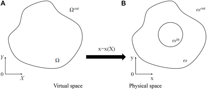
FIGURE 1. (A) The virtual space of acoustic cloak coordinate transformation. (B) The physical space of acoustic cloak coordinate transformation.
By designing the material parameters of the ω area, the sound wave can bypass the ωin area, and at the same time, ensure that the sound pressure fields of the Ωout and ωout areas are the same so as to realize the acoustic stealth function of the ωin area.
Assuming that the outer boundaries of virtual space Ω and physical space ω are the same, rectangular coordinate systems XOY and xoy are established, respectively, and the mapping function is x = x (X). The stealth gradient of the virtual space is defined as
The mapping relationship can be deduced as follows:
where J is the Jacobian determinant of F.
The fluid sound pressure control equation of the virtual space is
where v is the velocity vector and p is the fluid sound pressure.
By introducing the operator mapping in formula (2) into formula (3) and introducing the passive symmetric second order tensor S (satisfying
The elastic matrix of the underwater acoustic absorber material has only one non-zero eigenvalue, which is expressed as in the tensor form. In the x-coordinate system, according to Formula (4, 5), the material parameter distribution of the acoustic cloak in the physical space can be obtained as follows:
For acoustic cloaks with special shapes such as two-dimensional annular and three-dimensional spherical shells, the circular transformation area (0 < R < b) in the virtual space can be mapped to a minimal annular area (a<r < b) in the physical space through coordinate transformation, as shown in Figure 2.
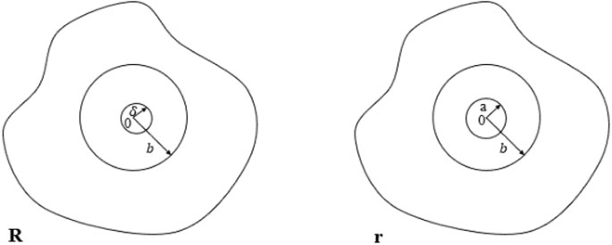
FIGURE 2. Schematic diagram of coordinate transformation of two-dimensional annular cloak.
Polar coordinate systems were established in both virtual and real spaces, considering the following mapping relationship between the virtual space
In order to avoid the problem of parameter singularity, a minimal positive parameter
Under this mapping relationship, the transformation matrix
In the annular symmetric structure, the coordinate variable tensor between the virtual space and the physical space is symmetric, and the special stress tensor can be constructed in the form of
where
According to the density distribution formula, it can be concluded that the quality of the acoustic cloak was the same as that of the background medium. Evidently, if other objects to be invisible were placed in the internal cavity area, the invisibility cloak will not be suspended in the background medium.
The mapping methods between virtual space and physical space include equal density mapping, equal modulus mapping, and linear mapping. The first mapping requires the widest range of anisotropy values, the second mapping requires the widest range of density values, and the third mapping requires a moderate range of both values. Therefore, this study focuses on the performance of acoustic cloaks based on linear mapping.
The range of the acoustic cloak in the physical space is a circle with an internal radius of a and an external radius of b. After the acoustic cloak transformation, the range in the virtual space was a circle with an internal radius of
where
Equation (10) is substituted into equation (9) to obtain the distribution equation of cloak parameters using linear mapping, which can be written in the following form:
Finite element simulation software COMSOL was used to simulate the case of plane wave incident on an aluminum cylinder in an ideal infinite fluid medium, and then the total sound field and scattering sound field of the aluminum cylinder were analyzed after plane wave incidence. In this example, the three-dimensional cylindrical problem is simplified to a two-dimensional annular problem, which can effectively reduce the calculation load.
The simulated area is a square area with a side length of 5m, and there is an aluminum cylinder with a radius of 0.3 m in the center. The plane acoustic wave with a frequency of 2 kHz is incident from the left port of the area. In order to simulate the propagation characteristics of the plane acoustic wave in the ideal infinite fluid medium, in COMSOL physical field analysis, the four sides of the square area are selected when setting the boundary condition of “plane wave radiation,” which can make the plane wave directly pass through the boundary without any reflection so as to simulate the infinite fluid. In this example and the following sound field simulation covering the acoustic cloak, the fluid medium in the background is water (
Figure 3 shows the sound field distribution diagram of the plane sound wave without cloak covering with a frequency of 2 kHz when it hits the cylinder from the left. Figure 3A shows the scattering sound field distribution of a plane wave when it is interfered by a cylinder. Figure 3B shows the total sound pressure distribution of a plane sound wave when it is incident and scattered by a cylinder. It is the result of the superposition of the background sound pressure and the scattering sound pressure. The scattering effect at the front and back of the cylinder was serious, leading to bending and displacement of the wave front, and the intermittent scattering sound pressure distribution at the upper and lower sides made the wave front fractured.
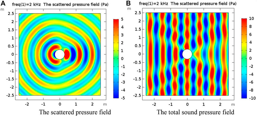
FIGURE 3. (A) The scattered pressure field without cloak covering with frequency of 2 kHz. (B) The total sound pressure field without cloak covering with frequency of 2 kHz.
Under the same conditions, the 10-layer acoustic cloak was covered on the obstacle. The sound field distribution in the flow area was studied, and its stealth ability was verified. The inner radius of the acoustic cloak is a = 0.3 m, and the outer radius is b = 1 m. After coordinate transformation, the target object with a radius of 0.3 m covered by the cloak is transformed into an equivalent scattering feature that is only equivalent to a circular microarea with a radius of
The sound pressure distribution of the acoustic cloak covering 10 layers can be seen in Figure 4. The acoustic cloak with linear mapping has a certain acoustic stealth effect, and the aluminum cylinder is almost free of pressure. It can be seen from the scattering sound pressure diagram that there is still a relatively weak scattering effect in front of the cloak and behind the cloak. The scattering effect on both sides of the cloak was small. The compression distribution of the sound track inside the cloak was relatively uniform. The equal sound pressure lines at the inner boundary were not concentrated. The interaction with obstacles was very small, and its acoustic stealth performance was affected little by the inner boundary.
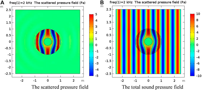
FIGURE 4. (A) The scattered pressure field covering 10 layers of acoustic cloak when the frequency is 2 kHz. (B) The total sound pressure field covering 10 layers of acoustic cloak when the frequency is 2 kHz.
At present, the method of layered discrete and parameter equivalent was adopted in the preparation of the invisibility cloak, and the material parameters of each layer will directly affect the invisibility effect of the cloak. In order to quantitatively describe the invisibility of the cloak, the dimensionless parameter scattering cross-section
where
For a layered design of the acoustic cloak, the number of layers is an important factor to be considered. Under the condition that the thickness of the cloak is constant and the frequency is 2 kHz, the stealth performance of the cloak with different layers was studied. The sound field simulation results are shown in Figure 5.
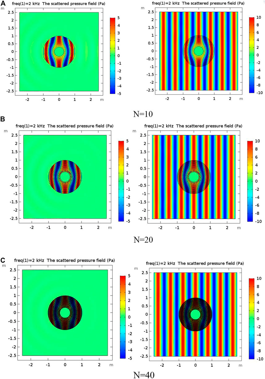
FIGURE 5. (A) Schematic diagram of sound field when the number of acoustic cloak layers is 10 when the frequency is 2KHz. (B) Schematic diagram of sound field when the number of acoustic cloak layers is 20 when the frequency is 2KHz. (C) Schematic diagram of sound field when the number of acoustic cloak layers is 40 when the frequency is 2KHz.
Figure 5 shows the sound field diagram of uniform layering when the number of layers of the acoustic cloak is 10, 20, and 40 at the frequency of 2 kHz. It can be seen from the scattering sound pressure diagram that with the increase of the number of layers N, the backscattered wave was significantly weakened, and the disturbance of the scatterer to the sound wave was getting smaller and smaller. When the number of layers of the acoustic cloak is 40, the stealth effect is better.
It can be seen from Table 1 that when the frequency is constant, the cloak thickness is the same, and the layers are evenly layered. With the increase in the number of layers N, the scattering cross-sectional value becomes smaller, and the stealth effect becomes better. However, due to the limited thickness of the cloak, the preparation difficulty will also increase significantly. Moreover, too few layers make the cloak’s stealth performance difficult to meet the use requirements. Therefore, the reasonable number of layers selected is of great significance to the practical application of the acoustic cloak.
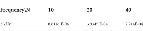
TABLE 1. Comparison of stealth effects of different layers.
It can be seen from the previous discussion that when the frequency is constant, the thickness of the cloak is the same, and the cloak is evenly layered, the number of layers of the cloak increases, the stealth effect is better, and the complexity of metamaterial preparation is also increased. The parameters of the stealth material vary unevenly with the radius, and the process of solving the scattering sound field is complex, so it is difficult to abstract a clear function expression of the scattering sound pressure. We hope to discuss the influence of the layer thickness distribution on the total acoustic scattering cross section of the layered cloak with the help of the optimization algorithm, and we try to design a low scattering cloak with only a few layers of polyurethane.
Many optimization algorithms have been proposed, including particle swarm optimization, genetic algorithm, and artificial neural network. Genetic algorithm has high efficiency in solving the global optimal solution, but has insufficient ability in local search. Particle swarm optimization (PSO) has the advantages of easy programming, high precision, and fast convergence, but it is prone to premature convergence and poor local optimization ability. Artificial neural network has the ability of adaptive learning and memory association, and is good at solving complex nonlinear problems, but its convergence speed is slow. In this study, the optimization algorithm combining the BP neural network and genetic algorithm is adopted, and genetic algorithm is used as the weight and structure training method of the BP neural network algorithm. Combining the advantages of both, the convergence speed and calculation accuracy are improved. Taking the minimum scattering cross section as the optimization objective, the BP neural network genetic algorithm is run in MATLAB, which is the acoustic module to simulate and calculate the scattering cross section of the cloak by COMSOL, and the layer thickness distribution corresponding to the best stealth effect was obtained through iterative calculation.
This study selects a cloak with a frequency of 2 kHz and five layers of acoustic cloak to optimize the layer thickness distribution with the goal of optimal stealth performance. The function extreme value optimization of the neural network genetic algorithm is mainly divided into two steps: BP neural network training fitting and genetic algorithm extreme value optimization. The algorithm flowchart is shown in Figure 6. A suitable BP neural network was constructed according to the characteristics of the optimization function. A total of 1,000 groups of radius values of each layer and corresponding scattering cross-sectional values calculated by COMSOL were imported to the BP neural network, of which 800 groups were selected as the training samples of the BP neural network, and the remaining 200 groups were used as the prediction input of the trained BP neural network. The prediction results of the trained BP neural network are used as individual fitness values during the optimization of the extreme value of the genetic algorithm, and the global optimal values and corresponding input values of the function are found through selection, crossover, and mutation operations.
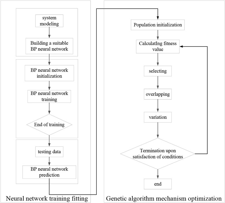
FIGURE 6. Flowchart of extreme value optimization of the neural network genetic algorithm.
The optimization model in this study has four input parameters and one output parameter, so the BP neural network structure is 4–11–1. A total of 1,000 groups of input and output data of the function are taken, of which 800 groups of data are randomly selected to train the network, 200 groups of data are selected to test the network performance, and then the trained network is used to predict the output.
The real number encoding method was used to encode individuals in the genetic algorithm. Since the number of input parameters of the optimization function is four, the proposed individual length is 4. The fitness value of the individual is set as the prediction value of the BP neural network. When the fitness value is smaller, the individual is better. The selection operator, crossover operator, and mutation operator are consistent, with a crossover probability of 0.4 and a mutation probability of 0.2.
Figure 7 shows the convergence curve of the optimization algorithm. In the early stage of calculation, the convergence is fast, and the optimal value is basically reached in about 20 generations. The radius distribution obtained by optimization calculation is 0.3, 0.4009, 0.5315, 0.6820, 0.8477, and 1 m. Table 2 shows the layer thickness parameters of the cloak after optimization and before optimization. Figure 8 is the schematic diagram of the optimized sound field. Compared with the material distribution and sound field schematic diagram of the cloak before optimization (Figure 9), it can be seen that the cloak scattering effect decreases when compared with the average layer thickness. By comparing the acoustic field before and after optimization, it can be seen that the impact of the optimized incident plane wave is smaller and the scattering effect is weaker. The scattering cross area of the optimized layer thickness distribution is
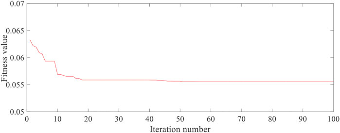
FIGURE 7. Convergence curve of optimization calculation.

TABLE 2. Layer thickness of the cloak after and before optimization.
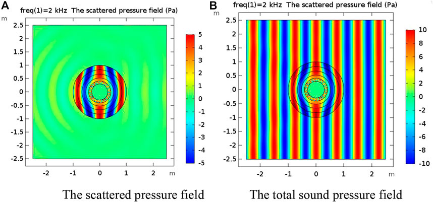
FIGURE 8. (A) The scattered pressure field after cloak structure optimization. (B) The total sound pressure field after cloak structure optimization.
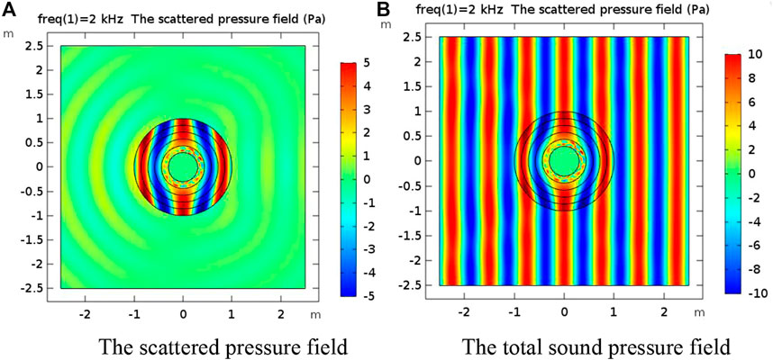
FIGURE 9. (A) The scattered pressure field before cloak structure optimization. (B) The total sound pressure field before cloak structure optimization.
Based on the optimization simulation results of COMSOL, the density, shear modulus, Poisson’s ratio, and bulk modulus parameters of each layer of the stealth material are obtained as shown in Table 3 so as to prepare a polyurethane underwater sound absorber.
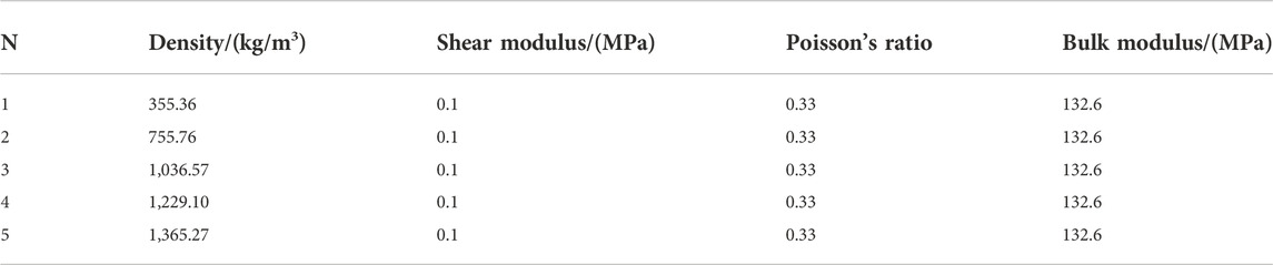
TABLE 3. Material distribution of the polyurethane underwater sound absorber.
The acoustic cloak has become a new and popular research direction in the field of scientific research in the past decade, and has a very broad application value in medical, civil engineering, military, and other fields. The acoustic cloak designed by combining pentamode materials with the coordinate transformation theory provides a feasible method for sound wave control. Due to the limitation of objective conditions such as preparation technology, the acoustic cloak needs to be discretized into several pentamode material layers during design and manufacture. In order to obtain the best stealth ability, this study takes the two-dimensional annular acoustic cloak as the research object, uses COMSOL acoustic field simulation, and combines the BP neural network genetic algorithm to analyze the influence of layer thickness distribution on the stealth performance of the acoustic cloak. The results show that when the cloak thickness is given and the frequency is constant, the stealth effect is better with the increase in the number of layers under the condition of uniform layering. Through optimization calculation, a reasonable layer thickness distribution is selected to obtain the parameter distribution of a polyurethane underwater absorption material, which can effectively improve the stealth effect.
The original contributions presented in the study are included in the article/Supplementary Material. Further inquiries can be directed to the corresponding author.
FW: conceptualization, methodology, software, investigation, analysis, and writing—original draft; SC: visualization and writing—review; JX: data curation and writing—original draft.
The authors declare that the research was conducted in the absence of any commercial or financial relationships that could be construed as a potential conflict of interest.
All claims expressed in this article are solely those of the authors and do not necessarily represent those of their affiliated organizations, or those of the publisher, the editors, and the reviewers. Any product that may be evaluated in this article, or claim that may be made by its manufacturer, is not guaranteed or endorsed by the publisher.
1. Li HX, Liang B, Cheng JC. Recent advances in the artificial structure-based manipulation of the acoustic field. Scientia Sinica Physica, Mechanica & Astronomica (2022) 52(04):6–33. in Chinese. doi:10.1360/SSPMA-2021-0292
2. Pendry J, Schurig D, Smith D. Controlling electromagnetic fields. Science (2006) 312(5781):1780–2. doi:10.1126/science.1125907
3. Muhammad LCW. From photonic crystals to seismic metamaterials: A Review via phononic crystals and acoustic metamaterials. Arch Comput Methods Eng (2022) 29(29):1137–98. doi:10.1007/s11831-021-09612-8
4. Chen Y, Liu XN, Xiang P, Hu GK. Pentamode material for underwater acoustic wave control. Adv Mech (2016) 46(1):53. in Chinese, doi:10.6052/1000-0992-16-010
5. Xu WL, Peng WC, Zhang JJ, He HS. Prospects of acoustic metamaterials for acoustic stealth. Chin J Ship Res (2020) 15(4):19–27. in Chinese, doi:10.19693/j.issn.1673-3185.01624
6. Norris AN. Acoustic cloaking theory. Proc R Soc A (2008) 464(2097):2411–34. doi:10.1098/rspa.2008.0076
7. Scandrett CL, Boisvert JE, Howarth TR. Acoustic cloaking using layered pentamode materials. The J Acoust Soc America (2010) 127(5):2856–64. doi:10.1121/1.3365248
8. Scandrett CL, Boisvert JE, Howarth TR. Broadband optimization of a pentamode-layered spherical acoustic waveguide. Wave Motion (2011) 48(6):505–14. doi:10.1016/j.wavemoti.2011.02.007
9. Gokhale NH, Cipolla JL, Norris AN. Special transformations for pentamode acoustic cloaking. J Acoust Soc America (2012) 132(4):2932–41. doi:10.1121/1.4744938
10. Zhang XD, Chen H, Wang L, Zhao ZG, Zhao AG. Theoretical and numerical analysis of layered cylindrical pentamode acoustic cloak. Acta Physica Sinica (2015) 8(13). in Chinese. doi:10.7498/aps.64.134303
11. Zhang YB, Ren CY, Zhu X. Research status of functionally gradient materials for underwater target acoustic stealth. Mater Rep (2013) 27(07):59–62. in Chinese. doi:10.3969/j.issn.1005-023X.2013.07.013
12. Zhang LF. Development and application of polyurethane underwater sound absorbing materials. Rubber Plastics Resour Utilization (2021)(05) 31–4+38. in Chinese.
13. Bückmann T, Thiel M, Kadic M, Schittny R, Wegener M. An elasto-mechanical unfeelability cloak made of pentamode metamaterials. Nat Commun (2014) 5:4130. doi:10.1038/ncomms5130
14. Bückmann T, Kadic M, Schittny R, Wegener M. Mechanical cloak design by direct lattice transformation. Proc Natl Acad Sci U S A (2015) 112(16):4930–4. doi:10.1073/pnas.1501240112
15. Kadic M, Bäuckmann T, Stenger N, Thiel M, Wegener M. On the practicability of pentamode mechanical metamaterials. Appl Phys Lett (2012) 100(1-4):191901. doi:10.1063/1.4709436
16. Martin A, Kadic M, Schittny R, Bückmann T, Wegener M. Phonon band structures of three-dimensional pentamode metamaterials. Phys Rev B Condensed Matter (2012) 86(15):4172–81. doi:10.1103/PhysRevB.86.155116
17. Kadic M, Bäuckmann T, Schittny R, Wegener M. On anisotropic versions of three-dimensional pentamode metamaterials. New J Phys (2013) 15:023029–23040. doi:10.1088/1367-2630/15/2/023029
18. Layman CN, Naify CJ, Martin TP, Calvo DC, Orris GJ. Highly anisotropic elements for acoustic pentamode applications. Phys Rev Lett (2013) 111(2):024302. doi:10.1103/physrevlett.111.024302
19. Norris A, Vasseur J, Haw G, Croenne C, Haumesser L, Hladky-Hennion AC. Negative refraction and focusing of acoustic waves using a foam-like metallic structure. J Acoust Soc America (2013) 134(5):4027. doi:10.1121/1.4830703
20. Norris AN. Acoustic metafluids. J Acoust Soc America (2009) 125(2):839–49. doi:10.1121/1.3050288
21. Hladky-Hennion AC, Vasseur JO, Haw G, Croenne C, Haumesser L, Norris AN. Negative refraction of acoustic waves using a foam-like metallic structure. Appl Phys Lett (2013) 102:144103. doi:10.1063/1.4801642
22. Chen Y, Liu XN, Hu GK. Latticed pentamode acoustic cloak. Sci Rep (2015) 5:15745. doi:10.1038/srep15745
23. Chen Y, Zheng M, Liu X, Bi Y, Sun Z, Xiang P, et al. Broadband solid cloak for underwater acoustics. Phys Rev B (2017) 95(18):180104.1–180104.5. doi:10.1103/PhysRevB.95.180104
24. Wang C. Research on annular acoustic cloak based on Pentamode Material. MS Thesis. Nanjing: Nanjing University of Aeronautics and Astronautics (2018).
25. Liao G, Luan C, Wang Z. Acoustic metamaterials: A Review of theories, structures, fabrication approaches, and applications. Adv Mater Tech (2021) 6(05):1–29. doi:10.1002/admt.202000787
26. Quadrelli DE, Cazzulani G, Riviera SL, Braghin F Acoustic scattering reduction of elliptical targets via pentamode near-cloaking based on transformation acoustics in elliptic coordinates[J]. J Sound Vibration (2021) 512, doi:10.1016/j.jsv.2021.116396
27. Quadrelli DE, Casieri MA, Cazzulani G, La Riviera S, Braghin F. Experimental validation of a broadband pentamode elliptical-shaped cloak for underwater acoustics. Extreme Mech Lett (2021) 49:101526. doi:10.1016/j.eml.2021.101526
28. Fujii G, Takahashi M, Akimoto Y. Acoustic cloak designed by topology optimization for acoustic–elastic coupled systems. Appl Phys Lett (2021) 118(10):101102. doi:10.1063/5.0040911
29. Nie X, Chen Y, Liu X. Scattering analysis and optimization of spherical acoustic cloak with unideal pentamode material. Acta Mech Solida Sin (2020) 33(3):347–60. doi:10.1007/s10338-019-00139-x
Keywords: polyurethane material, acoustic cloak, BP neural network genetic algorithm, acoustic steal, scattering area
Citation: Wang F, Chang S and Xie J (2022) Design of a polyurethane underwater sound absorber based on the BP neural network and genetic algorithm. Front. Phys. 10:1080667. doi: 10.3389/fphy.2022.1080667
Received: 26 October 2022; Accepted: 01 November 2022;
Published: 25 November 2022.
Edited by:
Han Zhang, Institute of Acoustics, Chinese Academy of Sciences, ChinaCopyright © 2022 Wang, Chang and Xie. This is an open-access article distributed under the terms of the Creative Commons Attribution License (CC BY). The use, distribution or reproduction in other forums is permitted, provided the original author(s) and the copyright owner(s) are credited and that the original publication in this journal is cited, in accordance with accepted academic practice. No use, distribution or reproduction is permitted which does not comply with these terms.
*Correspondence: Jie Xie, dHp4aWVqaWUxOTkyQDE2My5jb20=
Disclaimer: All claims expressed in this article are solely those of the authors and do not necessarily represent those of their affiliated organizations, or those of the publisher, the editors and the reviewers. Any product that may be evaluated in this article or claim that may be made by its manufacturer is not guaranteed or endorsed by the publisher.
Research integrity at Frontiers
Learn more about the work of our research integrity team to safeguard the quality of each article we publish.